
05 / Hazardous-area cable entry
Explosion-Protected Cable Glands
Explosion-protected glands connect cables to equipment used in hazardous areas. The range includes different sealing and armour-clamping constructions. Selection depends on the equipment protection concept, cable build and the certificate and installation instructions for the gland.
- Cable construction and dimensions
- Protection concept and equipment entry
- Current certificate and market scope
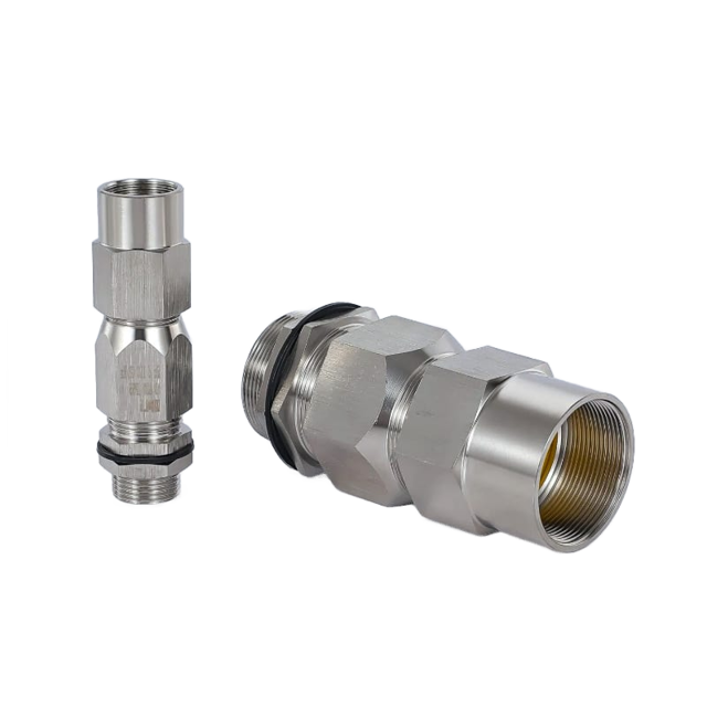
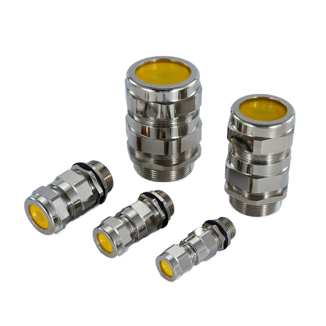
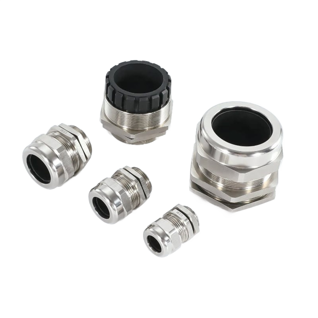


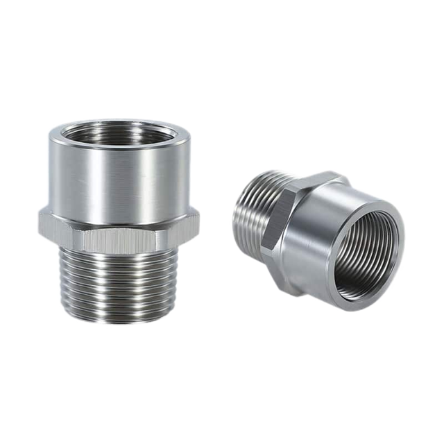


Cable gland families
Compare cable glands by material, cable construction and duty.
Choose nylon, brass or stainless steel by body material, or compare EMC, armoured, hazardous-area, marine and conduit-entry designs by the job they must perform.
Explosion-Protected Cable Glands range
Choose your explosion-protected cable glands
Cable-entry designs for armoured and unarmoured cables on hazardous-area equipment.
Models & dimensions
Explosion-Protected Cable Glands: specifications and dimensions
Select a product to see its specifications, drawings and sizes.
Explosion-Protected Cable Glands
Which fitting do you need?
Choose a product above, or show all products to compare sizes and construction.- 01Cable and seal range
- 02Entry thread and dimensions
- 03Material and installation duty
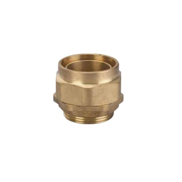
BW Cable Gland for Indoor SWA Cable
01 / Hazardous-area cable entry
BW Cable Gland for Indoor SWA Cable
A BW two-part brass gland that locks steel-wire armour at an indoor, dry cable entry.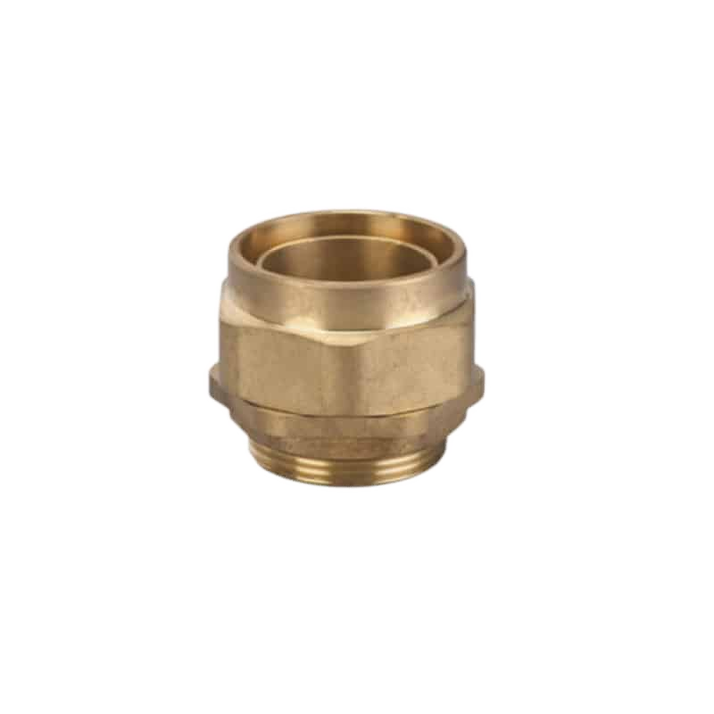
Product reference
- Construction
- BW & CW Armoured Glands
- Application
- An SWA cable requires a BW armour-lock construction for an indoor, dry location.
Key specifications
- Gland Type
- BW 2-Part Armour Lock
- Application
- Indoor & Dry locations, for SWA (Steel Wire Armour) Cable
- Material
- Brass (Optional Nickel Plating)
- Protection Rating
- IP30
Product specifications
Construction and details

Separated assembly components
Compare the arrangement of the illustrated parts. Confirm the assembly instructions for the selected model.
Further specifications
- Thread Options
- Metric, NPT, BSP, PG
- Accessories
- Locknut, Earth Tag, PVC Shroud
Key features
- Two-part armour lockThe BW construction mechanically retains the steel-wire armour.
- Indoor, dry applicationThe BW form is intended for indoor and dry locations.
- Accessory optionsLocknuts, earth tags and PVC shrouds are available for the installation.
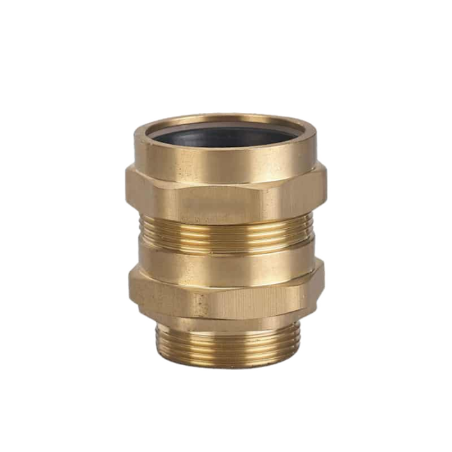
CW Single-Compression Cable Gland for SWA
02 / Hazardous-area cable entry
CW Single-Compression Cable Gland for SWA
A CW single-compression brass cable gland for steel-wire-armoured cable, with sealing and armour retention at the entry.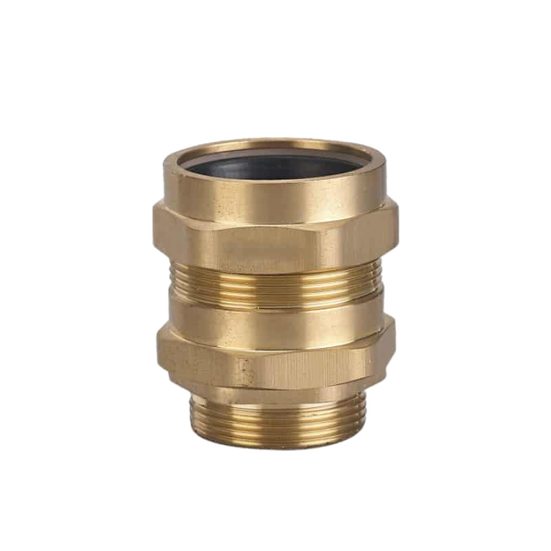
Product reference
- Construction
- BW & CW Armoured Glands
- Application
- An SWA cable installation requires a CW single-compression sealing construction.
Key specifications
- Gland Type
- CW Single Compression
- Application
- Steel-wire-armoured cable entries
- Material
- Brass (Optional Nickel Plating)
- Protection Rating
- IP66 / IP67
Product specifications
Construction and details

Separated assembly components
Compare the arrangement of the illustrated parts. Confirm the assembly instructions for the selected model.
Further specifications
- Operating Temperature
- -20°C to +80°C
- Thread Options
- Metric, NPT, BSP, PG
- Accessories
- Locknut, Earth Tag, PVC Shroud
Key features
- Single-compression formThe CW construction combines an armour-retention arrangement with a cable seal.
- Brass bodyThe body is brass, with nickel plating available as an option.
- Installation accessoriesThe range includes locknuts, earth tags and PVC shrouds.
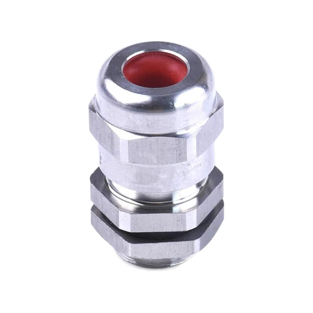
Ex-V Single-Seal Armoured Cable Gland
03 / Hazardous-area cable entry
Ex-V Single-Seal Armoured Cable Gland
An Ex-V single-seal metal gland with armour clamping for steel-wire and braided armoured cable constructions.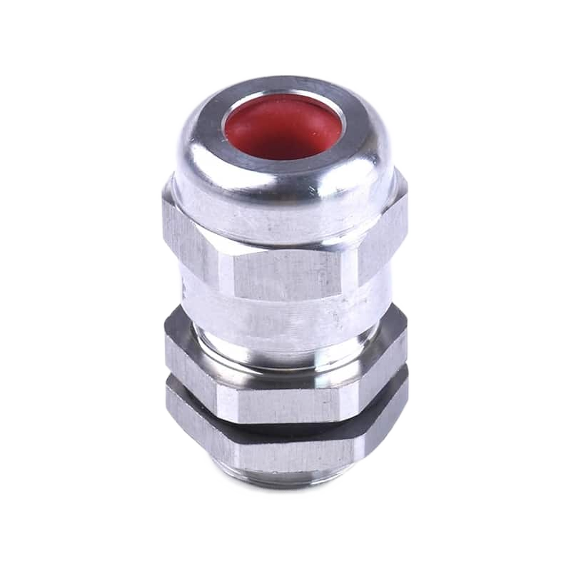
Product reference
- Construction
- Ex-V Single-Seal Glands
- Application
- An armoured-cable installation calls for the Ex-V single-seal arrangement.
Key specifications
- Product Type
- Single-seal armoured cable gland
- Model
- Ex-V
- Body Material
- Brass or stainless steel
- Seal Material
- Silicone or NBR
Product specifications
Construction and details

Assembly arrangement and dimensions
Compare the arrangement of the illustrated parts. Confirm the assembly instructions for the selected model.
Read the marked dimensions with the current model drawing; do not infer sizes by measuring the illustration.
Model specification tablesFurther specifications
- Applicable Cable
- Steel Wire Armour (SWA), Braided Armour, Jacketed Armour
Key features
- Single-seal constructionEx-V combines a single sealing arrangement with armour retention.
- Body and seal optionsThe range includes brass or stainless-steel bodies with silicone or NBR sealing options.
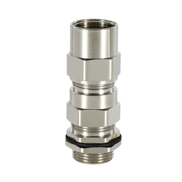
Ex-VIIG Double-Seal Armoured Cable Gland
04 / Hazardous-area cable entry
Ex-VIIG Double-Seal Armoured Cable Gland
An Ex-VIIG metal cable gland with double sealing and an armour-clamping system.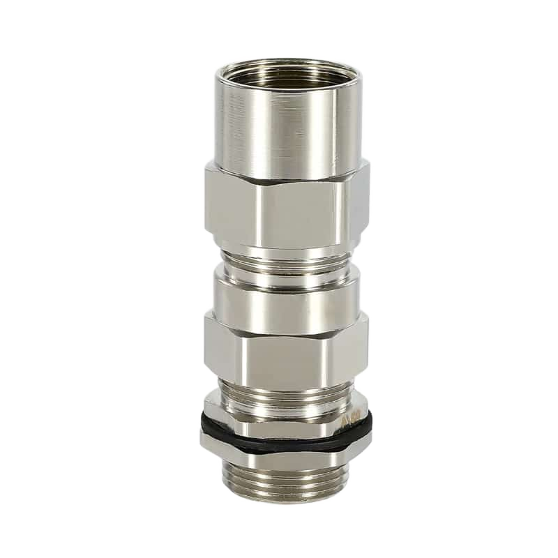
Product reference
- Construction
- Ex-VIIG Double-Seal Glands
- Application
- An armoured cable entry requires the Ex-VIIG double-seal arrangement.
Key specifications
- Product Type
- Double-seal armoured cable gland
- Model
- Ex-VIIG / BDM-VIIG
- Body Material
- Nickel-Plated Brass / Stainless Steel (304, 316)
- Seal Material
- Silicone Rubber
Product specifications
Construction and details

Separated assembly components
Compare the arrangement of the illustrated parts. Confirm the assembly instructions for the selected model.
This illustration does not establish the current model’s certification or approval.

Section view and dimension markers
Read the marked dimensions with the current model drawing; do not infer sizes by measuring the illustration.
Drawing markers: AG · GL
Model specification tablesFurther specifications
- Ingress Protection
- IP66
- Operating Temperature
- -60°C to +100°C
- Applicable Cable
- Steel Wire, Braided, and Steel Tape Armoured Cables
Key features
- Double-seal arrangementTwo sealing stages accompany the armour-clamping system.
- Silicone sealing partsThe gland uses silicone seals.
- Brass and stainless optionsThe range includes nickel-plated brass and 304 or 316 stainless-steel bodies.
Ex-VIIIG Single-Seal Armoured Cable Gland
05 / Hazardous-area cable entry
Ex-VIIIG Single-Seal Armoured Cable Gland
An Ex-VIIIG gland combining single sealing and armour clamping for wire-, braid- or tape-armoured cable.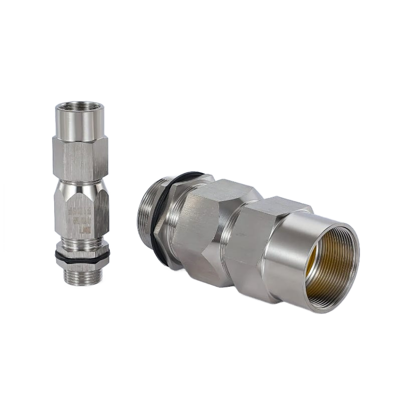
Product reference
- Construction
- Ex-VIIIG Single-Seal Glands
- Application
- An armoured cable requires the Ex-VIIIG single-seal construction.
Key specifications
- Product Type
- Single-seal armoured cable gland
- Model
- Ex-VIIIG / BDM-VIIIG
- Body Material
- Nickel-Plated Brass / Stainless Steel (304, 316)
- Seal Material
- Silicone Rubber
Product specifications
Construction and details

Separated assembly components
Compare the arrangement of the illustrated parts. Confirm the assembly instructions for the selected model.
This illustration does not establish the current model’s certification or approval.

Section view and dimension markers
Read the marked dimensions with the current model drawing; do not infer sizes by measuring the illustration.
Drawing markers: AG · GL
Model specification tablesFurther specifications
- Ingress Protection
- IP66
- Operating Temperature
- -60°C to +100°C
- Applicable Cable
- Steel Wire, Braided, and Steel Tape Armoured Cables
Key features
- Single sealing with armour clampingThe Ex-VIIIG form combines one sealing arrangement with mechanical armour retention.
- Silicone sealsThe sealing components use silicone rubber.
- Metal body choicesNickel-plated brass and 304 or 316 stainless-steel versions are available.
Ex-VII Double-Seal Armoured Cable Gland
06 / Hazardous-area cable entry
Ex-VII Double-Seal Armoured Cable Gland
An Ex-VII metal cable gland with double sealing and an armour-clamping arrangement for wire-, braid- or tape-armoured cable.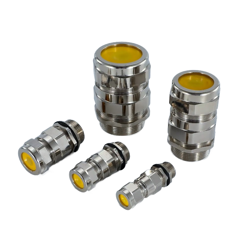
Product reference
- Construction
- Ex-VII Double-Seal Glands
- Application
- An armoured cable requires the Ex-VII double-seal construction.
Key specifications
- Product Type
- Double-seal armoured cable gland
- Model
- Ex-VII d/e BDM
- Body Material
- Nickel-plated brass, SS304 stainless steel, or SS316 stainless steel
- Seal Material
- Silicone Rubber
Product specifications
Construction and details

Separated assembly components
Compare the arrangement of the illustrated parts. Confirm the assembly instructions for the selected model.
This illustration does not establish the current model’s certification or approval.

Section view and dimension markers
Read the marked dimensions with the current model drawing; do not infer sizes by measuring the illustration.
Drawing markers: AG · GL
Model specification tablesFurther specifications
- Ingress Protection
- IP66
- Operating Temperature
- -60°C to +100°C
- Applicable Cable
- Steel Wire, Braided, and Steel Tape Armoured Cables
Key features
- Double sealingThe Ex-VII construction incorporates two sealing stages with armour clamping.
- Silicone sealsThe gland uses silicone sealing parts within a nickel-plated brass body.
- Armoured-cable formsThe construction covers steel-wire, braided and steel-tape armour arrangements.
Ex-B Cable Gland for Unarmoured Cable
07 / Hazardous-area cable entry
Ex-B Cable Gland for Unarmoured Cable
An Ex-B metal cable gland for unarmoured cable, with NBR, PTFE or silicone sealing options.
Product reference
- Construction
- Ex-B & Ex-BG Glands
- Application
- An unarmoured cable entry calls for the Ex-B construction and a specified seal material.
Key specifications
- Product Type
- Cable gland for unarmoured cable
- Model
- BDM Ex-B
- Body Material
- Nickel-Plated Brass / Stainless Steel
- Seal Material
- NBR, PTFE, or Silicone
Product specifications
Construction and details

Separated assembly components
Compare the arrangement of the illustrated parts. Confirm the assembly instructions for the selected model.
This illustration does not establish the current model’s certification or approval.

Section view and dimension markers
Read the marked dimensions with the current model drawing; do not infer sizes by measuring the illustration.
Drawing markers: AG · GL
Model specification tablesFurther specifications
- Ingress Protection
- IP68
- Operating Temperature
- -40°C to +100°C
- Applicable Cable
- Non-Armoured Cables
Key features
- Unarmoured cable entryThe Ex-B construction clamps an unarmoured cable at the enclosure entry.
- Seal-material optionsNBR, PTFE and silicone options address different sealing-material requirements.
- Metal body optionsNickel-plated brass and stainless-steel bodies are available.
Ex-BG Clamping Gland for Unarmoured Cable
08 / Hazardous-area cable entry
Ex-BG Clamping Gland for Unarmoured Cable
An Ex-BG metal clamping gland for unarmoured cable, with NBR, PTFE or silicone sealing options and Metric, NPT or G entries.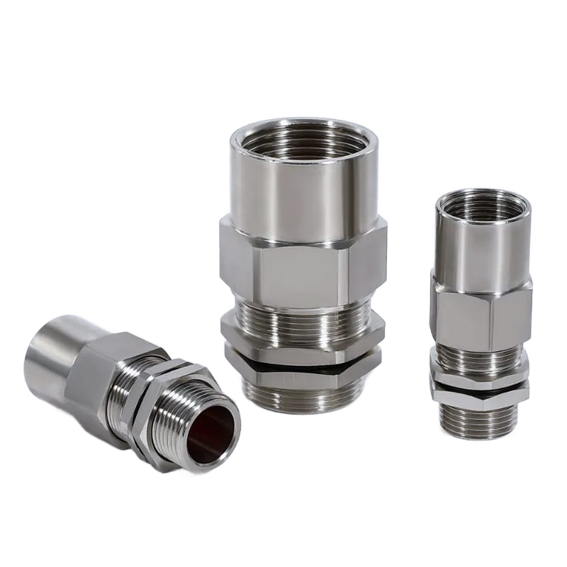
Product reference
- Construction
- Ex-B & Ex-BG Glands
- Application
- An unarmoured cable entry needs NBR, PTFE or silicone seal options with a Metric, NPT or G connection.
Key specifications
- Product Type
- Clamping gland for unarmoured cable
- Model
- BDM-BG / Ex-BG
- Body Material
- Nickel-Plated Brass / Stainless Steel
- Seal Material
- NBR, PTFE, or Silicone
Product specifications
Construction and details

Section view and dimension markers
Read the marked dimensions with the current model drawing; do not infer sizes by measuring the illustration.
Drawing markers: AG · GL
Model specification tables
Separated assembly components
Compare the arrangement of the illustrated parts. Confirm the assembly instructions for the selected model.
This illustration does not establish the current model’s certification or approval.
Further specifications
- Ingress Protection
- IP66
- Operating Temperature
- -40°C to +100°C
- Applicable Cable
- Non-Armoured Cables
Key features
- Unarmoured-cable clampEx-BG retains the cable without an armour-clamping assembly.
- Three seal-material optionsNBR, PTFE and silicone are available as configuration options.
- Three entry-thread systemsMetric, NPT and G versions serve different equipment entries.
Ex-VI Clamping Gland for Unarmoured Cable
09 / Hazardous-area cable entry
Ex-VI Clamping Gland for Unarmoured Cable
An Ex-VI metal clamping gland for unarmoured cable, with NBR or silicone sealing parts.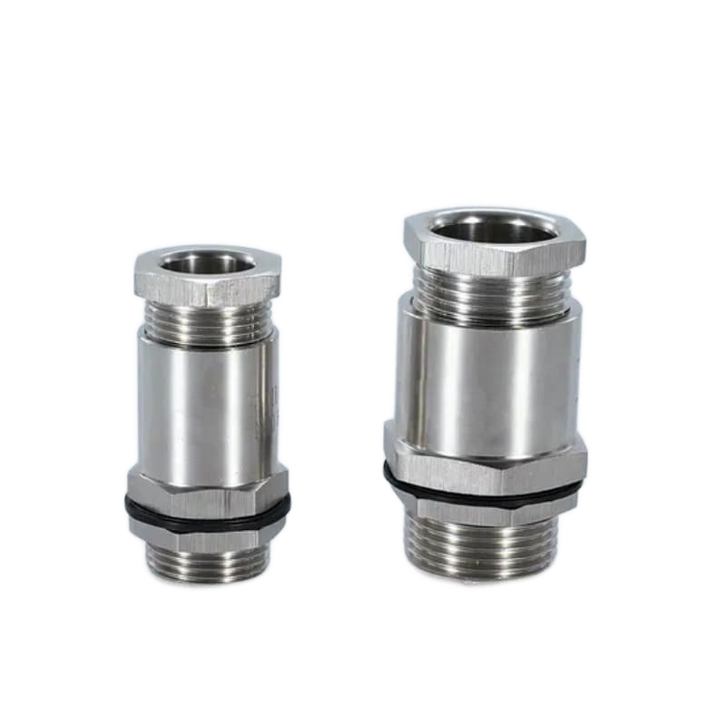
Product reference
- Construction
- Ex-VI & Ex-VIG Glands
- Application
- An unarmoured cable needs an Ex-VI clamping gland at a threaded equipment entry.
Key specifications
- Product Type
- Clamping gland for unarmoured cable
- Model
- Ex-VI
- Body Material
- Nickel-plated brass, SS304 stainless steel, or SS316 stainless steel
- Seal Material
- NBR or Silicone
Product specifications
Construction and details

Separated assembly components
Compare the arrangement of the illustrated parts. Confirm the assembly instructions for the selected model.
This illustration does not establish the current model’s certification or approval.

Section view and dimension markers
Read the marked dimensions with the current model drawing; do not infer sizes by measuring the illustration.
Drawing markers: AG · H · GL
Model specification tablesFurther specifications
- Ingress Protection
- IP66
- Operating Temperature
- -60°C to +100°C
- Applicable Cable
- Non-Armoured Cables
Key features
- Cable-clamping constructionEx-VI retains the unarmoured cable within the metal body.
- Two seal optionsThe sealing arrangement uses NBR or silicone, depending on the configuration.
- Entry threadsMetric, NPT and G versions are included in this construction.
Ex-VIG Clamping Gland for Unarmoured Cable
10 / Hazardous-area cable entry
Ex-VIG Clamping Gland for Unarmoured Cable
An Ex-VIG clamping gland for unarmoured cable, offered in nickel-plated brass and stainless-steel body configurations.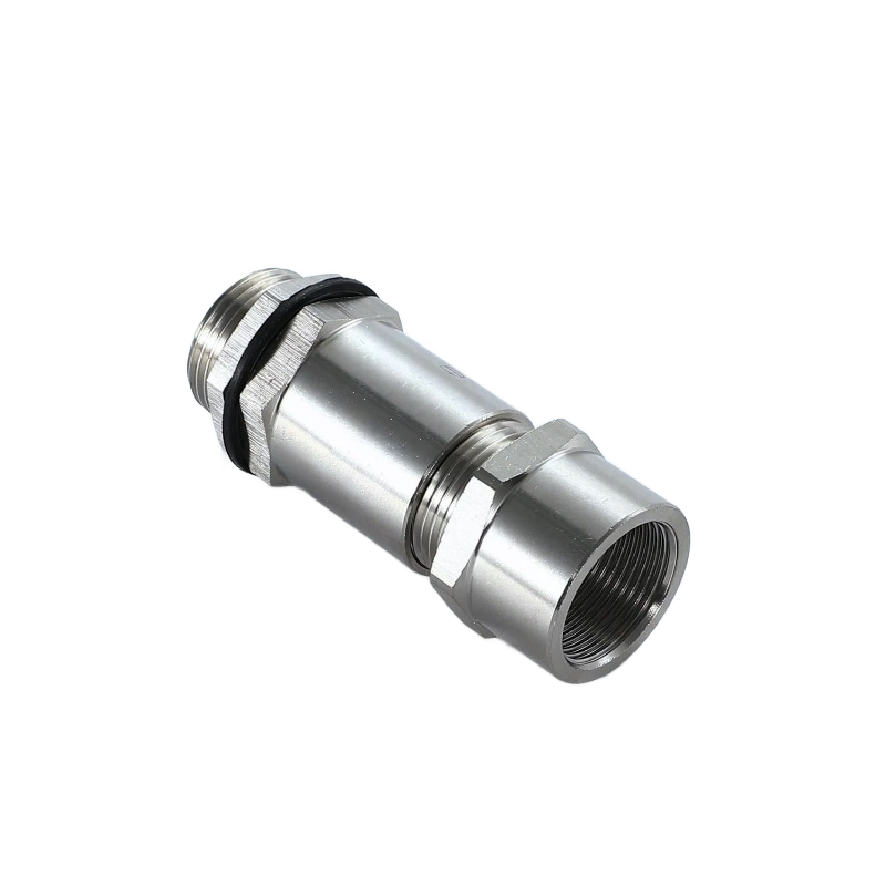
Product reference
- Construction
- Ex-VI & Ex-VIG Glands
- Application
- A clamping gland with a nickel-plated brass or stainless steel body.
Key specifications
- Product Type
- Clamping gland for unarmoured cable
- Model
- BDM-VIG / Ex-VIG
- Body Material
- Nickel-Plated Brass / Stainless Steel (304, 316)
- Seal Material
- NBR or Silicone
Product specifications
Construction and details

Separated assembly components
Compare the arrangement of the illustrated parts. Confirm the assembly instructions for the selected model.
This illustration does not establish the current model’s certification or approval.

Section view and dimension markers
Read the marked dimensions with the current model drawing; do not infer sizes by measuring the illustration.
Drawing markers: AG · H · GL
Model specification tablesFurther specifications
- Ingress Protection
- IP66
- Operating Temperature
- -60°C to +100°C
- Applicable Cable
- Non-Armoured Cables
Key features
- Ex-VIG model identityBDM-VIG and Ex-VIG identify this unarmoured-cable clamping construction.
- Body-material choicesThe range includes nickel-plated brass, 304 stainless steel and 316 stainless steel.
- Elastomer seal choicesNBR and silicone sealing options are available.
BGJ-A Female-to-Female Pipe Coupler
11 / Hazardous-area cable entry
BGJ-A Female-to-Female Pipe Coupler
A BGJ-A metal pipe coupler with female threads at both ends for joining threaded connections.
Product reference
- Construction
- BGJ Thread Accessories
- Application
- Two male-threaded connections need a female-to-female coupler.
Key specifications
- Product Type
- Female-to-female pipe coupler / reducer
- Model
- BGJ-A
- Body Material
- Nickel-Plated Brass / Stainless Steel
- Thread 1 (Female)
- G (BSP) (Standard); M, NPT (Custom)
Product specifications
Construction and details

Section view and dimension markers
Read the marked dimensions with the current model drawing; do not infer sizes by measuring the illustration.
Drawing markers: L
Model specification tablesFurther specifications
- Thread 2 (Female)
- G (BSP) (Standard); M, NPT (Custom)
- Ingress Protection
- IP65
Key features
- Two female-thread endsThe coupler joins male-threaded mating components.
- Straight or reducing formsBGJ-A includes straight and reducing connection forms.
- Metal body optionsNickel-plated brass and stainless-steel versions are available.
BGJ-B Thread Adapter — Reducer and Enlarger
12 / Hazardous-area cable entry
BGJ-B Thread Adapter — Reducer and Enlarger
A BGJ-B metal thread adapter for changing the connection size at a threaded entry.
Product reference
- Construction
- BGJ Thread Accessories
- Application
- The equipment entry and adjoining connection need different thread sizes.
Key specifications
- Product type
- Thread adapter — reducer or enlarger
- Body material
- Nickel-plated brass or stainless steel
- Model series
- BGJ-B
Product specifications
Construction and details

Section view and dimension markers
Read the marked dimensions with the current model drawing; do not infer sizes by measuring the illustration.
Drawing markers: L · GL
Model specification tablesKey features
- Reducer or enlarger functionThe adapter changes the threaded connection size.
- Metric, NPT and G seriesThe BGJ-B model tables cover Metric, NPT and G dimensional series.
- Metal constructionBrass and stainless-steel body options are available.
BGJ-C Male-to-Male Reducing Nipple
13 / Hazardous-area cable entry
BGJ-C Male-to-Male Reducing Nipple
A BGJ-C reducing nipple with male threads at both ends for joining female-threaded connections.
Product reference
- Construction
- BGJ Thread Accessories
- Application
- Two female-threaded components need a male-to-male connecting nipple.
Key specifications
- Connection
- Male-to-male threaded connection
- Body material
- Nickel-plated brass or stainless steel
- Model series
- BGJ-C
Product specifications
Construction and details

Section view and dimension markers
Read the marked dimensions with the current model drawing; do not infer sizes by measuring the illustration.
Drawing markers: L · GL
Model specification tablesKey features
- Male threads at both endsThe nipple screws into two female-threaded mating connections.
- Compact reducing connectionThe reducing form joins connections of different sizes.
- Metric, NPT and G seriesThe dimensional range includes Metric, NPT and G model series.
BGJ-D Male-to-Female Reducing Bushing
14 / Hazardous-area cable entry
BGJ-D Male-to-Female Reducing Bushing
A BGJ-D reducing bushing with a larger male thread around a smaller female-threaded opening.
Product reference
- Construction
- BGJ Thread Accessories
- Application
- A larger female-threaded entry needs to accept a smaller male-threaded component.
Key specifications
- Connection
- Larger male thread to smaller female thread
- Body material
- Nickel-plated brass or stainless steel
- Model series
- BGJ-D
- Ingress protection
- IP65
Product specifications
Construction and details

Section view and dimension markers
Read the marked dimensions with the current model drawing; do not infer sizes by measuring the illustration.
Drawing markers: L
Model specification tablesKey features
- Male-to-female reductionThe outside male thread fits the larger opening; the inside female thread receives the smaller component.
- Metric, NPT and G formsThe range includes reductions within Metric, NPT and G thread systems.
BDM-BDT / Ex-BDT Threaded Stopping Plug
15 / Hazardous-area cable entry
BDM-BDT / Ex-BDT Threaded Stopping Plug
A BDM-BDT / Ex-BDT metal stopping plug for closing an unused threaded enclosure opening.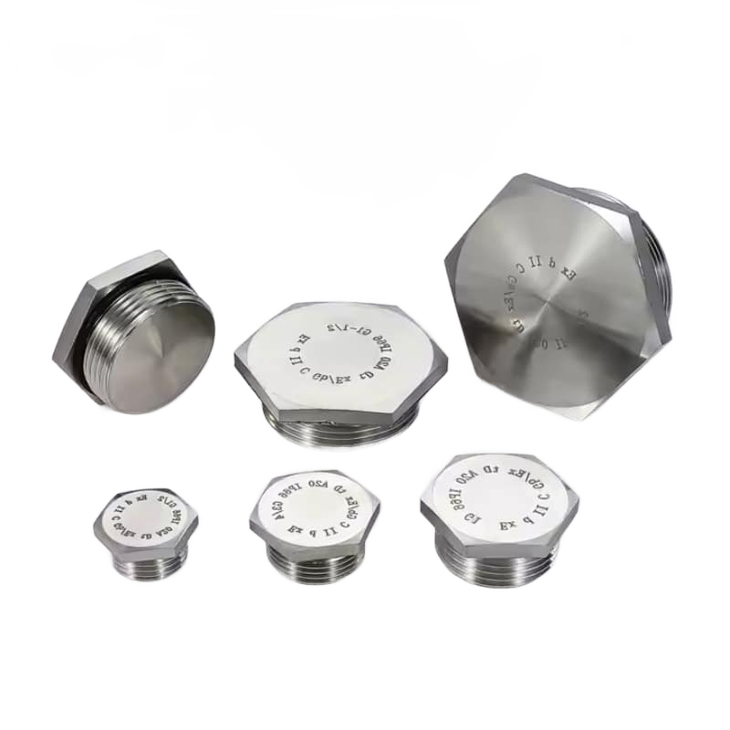
Product reference
- Construction
- Ex-BDT Stopping Glands
- Application
- A threaded enclosure entry is unused and needs a solid closure.
Key specifications
- Product Type
- Threaded stopping plug / blanking plug
- Model
- BDM-BDT / Ex-BDT
- Body Material
- Nickel-Plated Brass / Stainless Steel (304, 316)
- Seal Material
- NBR, PTFE or silicone
Product specifications
Construction and details

Section view and dimension markers
Read the marked dimensions with the current model drawing; do not infer sizes by measuring the illustration.
Drawing markers: H · GL · AG
Model specification tablesFurther specifications
- Ingress Protection
- IP66
- Operating Temperature
- -60°C to +100°C
Key features
- Solid threaded closureThe plug closes an opening without passing a cable through it.
- Metal body optionsNickel-plated brass and 304 or 316 stainless-steel versions are available.
Model specification tables
Model sizes
BW Cable Gland for Indoor SWA Cable
Hazardous-area cable entry
BW Cable Gland for Indoor SWA Cable
Model specificationsBW Cable Gland for Indoor SWA Cable — thread and cable dimensions
| Item Code | Thread Size (Metric) | Thread Size (NPT) | Min. Thread Length D (mm) | Unarmored Cable OD “A” (MIN–MAX, mm) | Armored Cable OD “B” (MIN–MAX, mm) |
|---|---|---|---|---|---|
| BW20S | M20 | 1/2″ | 10 | 11.50 | 15.50 |
| BW20L | M20 | 1/2″ | 10 | 14.00 | 20.50 |
| BW25S | M25 | 3/4″ | 10 | 18.00 | 24.00 |
| BW25L | M25 | 3/4″ | 10 | 20.00 | 27.00 |
| BW32S | M32 | 1″ | 10 | 26.30 | 33.50 |
| BW32L | M32 | 1″ | 10 | 26.30 | 33.50 |
| BW40S | M40 | 1-1/4″ | 13 | 31.50 | 39.50 |
| BW40L | M40 | 1-1/4″ | 13 | 32.00 | 40.00 |
| BW50S | M50 | 1-1/2″ | 13 | 38.20 | 46.30 |
| BW50L | M50 | 2″ | 13 | 44.00 | 52.60 |
| BW63S | M63 | 2″ | 14 | 50.10 | 59.00 |
| BW63L | M63 | 2-1/2″ | 14 | 56.00 | 65.30 |
| BW75S | M75 | 2-1/2″ | 15 | 62.00 | 71.60 |
| BW75L | M75 | 3″ | 15 | 68.00 | 78.00 |
| BW90 | M90 | 3″ | 20 | 80.50 | 91.00 |
CW Single-Compression Cable Gland for SWA
Hazardous-area cable entry
CW Single-Compression Cable Gland for SWA
Model specificationsCW Single-Compression Cable Gland for SWA — thread and cable dimensions
| Size Code | Thread outside diameter (mm) | Thread Length (mm) | Unarmored Cable OD “A” (MIN–MAX, mm) | Armored Cable OD “B” (MIN–MAX, mm) | Clamping Range (mm) | Wrench Size (mm) | Max Product OD (mm) |
|---|---|---|---|---|---|---|---|
| CW-20S | 20 | 10 | 6.0 – 10.0 | 8.0 – 15.8 | 0.9 / 1.25 | 24 | 27 |
| CW-20M | 20 | 10 | 8.0 – 11.8 | 12.9 – 17.2 | 0.9 / 1.25 | 27 | 30 |
| CW-20L | 20 | 10 | 11.0 – 14.0 | 15.5 – 20.8 | 0.9 / 1.25 | 30 | 33 |
| CW-25S | 25 | 10 | 12.0 – 17.0 | 17.5 – 24.0 | 1.25 / 1.60 | 34 | 36 |
| CW-25L | 25 | 10 | 13.0 – 20.3 | 24.0 – 26.5 | 1.25 / 1.60 | 36 | 39 |
| CW-32S | 32 | 12 | 17.0 – 24.0 | 25.0 – 32.0 | 1.60 / 2.00 | 44 | 46 |
| CW-32L | 32 | 12 | 19.0 – 26.2 | 26.7 – 34.0 | 1.60 / 2.00 | 46 | 48.5 |
| CW-40S | 40 | 14 | 23.0 – 27.0 | 31.0 – 37.0 | 1.60 / 2.00 | 52 | 57 |
| CW-40L | 40 | 14 | 25.0 – 32.2 | 33.0 – 40.5 | 1.60 / 2.00 | 55 | 58.5 |
| CW-50S | 50 | 15 | 31.5 – 37.0 | 39.4 – 45.0 | 2.00 / 2.50 | 58 | 65 |
| CW-50L | 50 | 15 | 36.5 – 42.0 | 45.7 – 50.0 | 2.00 / 2.50 | 65 | 72 |
| CW-63S | 63 | 15 | 42.5 – 47.0 | 52.1 – 56.0 | 2.5 | 68 | 75 |
| CW-63L | 63 | 15 | 49.1 – 56.0 | 58.4 – 66.0 | 2.5 | 80 | 89 |
| CW-75S | 75 | 15 | 54.5 – 58.0 | 64.8 – 68.0 | 2.5 | 82 | 90 |
| CW-75L | 75 | 15 | 57.5 – 64.0 | 68.0 – 74.0 | 2.5 | 92 | 103 |
| CW-90S | 90 | 15 | 66.0 – 76.0 | 77.0 – 86.0 | 2.50 / 3.15 | 106 | 118 |
| CW-90L | 90 | 15 | 66.0 – 79.0 | 77.0 – 90.0 | 2.50 / 3.15 | 106 | 118 |
| CW-100 | 100 | 17 | 80.0 – 90.9 | 92.0 – 101.5 | 3.15 / 4.00 | 123 | 135.3 |
| CW-115 | 115 | 17 | 87.0 – 97.9 | 101.0 – 110.3 | 3.15 / 4.00 | 133.4 | 146.7 |
Ex-V Single-Seal Armoured Cable Gland
Hazardous-area cable entry
Ex-V Single-Seal Armoured Cable Gland
Model specificationsEx-V — thread and cable dimensions
| Metric thread | Metric model | G/NPT thread size | NPT model | G model | Cable range B (mm) | Cable range A (mm) | H (mm) | L (mm) | Across flats (mm) | Across corners (mm) |
|---|---|---|---|---|---|---|---|---|---|---|
| M16*1.5 | Ex-V08-M16 | 3/8″ | Ex-V08-NPT3/8 | Ex-V08-G3/8 | 5-8 | 3-6 | 30 | 12 | 24 | 28 |
| M16*1.5 | Ex-V10-M16 | 3/8″ | Ex-V10-NPT3/8 | Ex-V10-G3/8 | 6-10 | 4-8 | 30 | 12 | 24 | 28 |
| M20*1.5 | Ex-V14-M20 | 1/2″ | Ex-V14-NPT1/2 | Ex-V14-G1/2 | 9-14 | 6-11 | 30 | 12 | 24 | 28 |
| M20*1.5 | Ex-V16-M20 | 1/2″ | Ex-V16-NPT1/2 | Ex-V16-G1/2 | 10-16 | 7-12 | 30 | 12 | 24 | 28 |
| M20*1.5 | Ex-V18-M20 | 1/2″ | Ex-V18-NPT1/2 | Ex-V18-G1/2 | 13-18 | 9-14 | 32 | 12 | 30 | 35 |
| M25*1.5 | Ex-V21-M25 | 3/4″ | Ex-V21-NPT3/4 | Ex-V21-G3/4 | 15-21 | 11-17 | 35 | 13 | 36 | 42 |
| M25*1.5 | Ex-V24-M25 | 3/4″ | Ex-V24-NPT3/4 | Ex-V24-G3/4 | 17-24 | 13-20 | 35 | 13 | 40 | 47 |
| M32*1.5 | Ex-V28-M32 | 1″ | Ex-V28-NPT1 | Ex-V28-G1 | 20-28 | 16-23 | 39 | 15 | 46 | 53 |
| M32*1.5 | Ex-VK2-M32 | 1″ | Ex-V32-NPT1 | Ex-V32-G1 | 23-32 | 18-26 | 39 | 15 | 46 | 53 |
| M40*1.5 | Ex-V35-M40 | 1-1/4″ | Ex-V35-NPT1-1/4 | Ex-V35-G1-1/4 | 26-35 | 21-29 | 43 | 15 | 55 | 64 |
| M40*1.5 | Ex-V38-M40 | 1-1/4″ | Ex-V38-NPT1-1/4 | Ex-V38-G1-1/4 | 31-38 | 25-32 | 43 | 15 | 55 | 64 |
| M50*1.5 | Ex-V41-M50 | 1-1/2″ | Ex-V41-NPT1-1/2 | Ex-V41-G1-1/2 | 34-41 | 28-35 | 48 | 15 | 65 | 75 |
| M50*1.5 | Ex-V44-M50 | 1-1/2″ | Ex-V44-NPT1-1/2 | Ex-V44-G1-1/2 | 37-44 | 31-38 | 48 | 15 | 65 | 75 |
| M63*1.5 | Ex-V50-M63 | 2″ | Ex-V50-NPT2 | Ex-V50-G2 | 40-50 | 33-43 | 53 | 16 | 80 | 92 |
| M63*1.5 | Ex-V55-M63 | 2″ | Ex-V55-NPT2 | Ex-V55-G2 | 43-55 | 36-47 | 53 | 16 | 80 | 92 |
| M75*1.5 | Ex-V63-M75 | 2-1/2″ | Ex-V63-NPT2-1/2 | Ex-V63-G2 | 50-63 | 42-53 | 58 | 16 | 96 | 111 |
| M75*1.5 | Ex-V68-M75 | 2-1/2″ | Ex-V68-NPT2-1/2 | Ex-V68-G2-1/2 | 54-68 | 45-58 | 58 | 16 | 96 | 111 |
| M88*2 | Ex-V72-M88 | 3″ | Ex-V72-NPT3 | Ex-V72-G3 | 62-72 | 52-62 | 64 | 18 | 114 | 134 |
| M88*2 | Ex-V79-M88 | 3″ | Ex-V79-NPT3 | Ex-V79-G3 | 67-79 | 56-67 | 64 | 18 | 114 | 134 |
| M110,2 | Ex-V89-M110 | 4″ | Ex-V89-NPT4 | Ex-V89-G4 | 78-89 | 65-75 | 70 | 18 | 128 | 148 |
| M110,2 | Ex-V105-M110 | 4″ | Ex-V105-NPT4 | Ex-V105-G4 | 38-104.5 | 74-91 | 70 | 18 | 138 | 148 |
Ex-VIIG Double-Seal Armoured Cable Gland
Hazardous-area cable entry
Ex-VIIG Double-Seal Armoured Cable Gland
Model specificationsMetric thread
| Metric Thread | Model | Locking Range (mm) | Max. Outlet (mm) | Thread Length GL (mm) | Thread outside diameter AG (mm) | Spanner size (mm) |
|---|---|---|---|---|---|---|
| M16 × 1.5 | Ex-VIIGM16 | 5-16 | 12 | 15 | 16 | 24 |
| M20 × 1.5 | Ex-VIIGM20 | 5-16 | 12 | 15 | 20 | 24 |
| M20 × 1.5D | Ex-VIIGM20D | 9-20 | 16 | 15 | 20 | 30 |
| M25 × 1.5 | Ex-VIIGM25 | 9-20 | 16 | 15 | 25 | 30 |
| M25 × 1.5D | Ex-VIIGM25D | 14-26 | 20 | 15 | 25 | 38 |
| M32 × 1.5 | Ex-VIIGM32 | 14-26 | 20 | 17 | 32 | 38 |
| M32 × 1.5D | Ex-VIIGM32D | 18-33 | 28 | 17 | 32 | 45 |
| M40 × 1.5 | Ex-VIIGM40-33 | 18-33 | 28 | 17 | 40 | 45 |
| M40 × 1.5D | Ex-VIIGM40D | 20-40 | 35 | 17 | 40 | 55 |
| M50 × 1.5 | Ex-VIIGM50 | 20-40 | 35 | 20 | 50 | 55 |
| M50 × 1.5D | Ex-VIIGM50D | 26-50 | 45 | 20 | 50 | 68 |
| M63 × 1.5 | Ex-VIIGM63 | 26-50 | 45 | 20 | 63 | 68 |
| M63 × 1.5D | Ex-VIIGM63D | 30-64 | 55 | 20 | 63 | 82 |
| M75 × 2 | Ex-VIIGM75 | 30-64 | 55 | 22 | 75 | 82 |
| M88 × 2 | Ex-VIIGM88 | 36-80 | 70 | 22 | 88 | 98 |
| M100 × 2 | Ex-VIIGM100 | 41-90 | 80 | 22 | 100 | 110 |
| M115 × 2 | Ex-VIIGM115 | 47-103 | 90 | 22 | 115 | 125 |
| M130 × 2 | Ex-VIIGM130 | 63-119 | 100 | 22 | 130 | 140 |
Model specificationsNPT thread
| NPT Thread | Model | Locking Range (mm) | Max. Outlet (mm) | Thread Length GL (mm) | Thread outside diameter AG (mm) | Spanner size (mm) |
|---|---|---|---|---|---|---|
| NPT 3/8 | Ex-VIIGNPT3/8 | 5-16 | 12 | 15 | 17.05 | 24 |
| NPT 1/2 | Ex-VIIGNPT1/2 | 5-16 | 12 | 15 | 21.22 | 24 |
| NPT 1/2D | Ex-VIIGNPT1/2D | 9-20 | 16 | 15 | 21.22 | 30 |
| NPT 3/4 | Ex-VIIGNPT3/4 | 9-20 | 16 | 15 | 26.56 | 30 |
| NPT 3/4D | Ex-VIIGNPT3/4D | 14-26 | 20 | 15 | 26.56 | 38 |
| NPT 1 | Ex-VIIGNPT1 | 14-26 | 20 | 17 | 33.28 | 38 |
| NPT 1D | Ex-VIIGNPT1D | 18-33 | 28 | 17 | 33.28 | 45 |
| NPT 1-1/4 | Ex-VIIGNPT1-1/4 | 18-33 | 28 | 17 | 41.98 | 45 |
| NPT 1-1/4D | Ex-VIIGNPT1-1/4D | 20-40 | 35 | 17 | 41.98 | 55 |
| NPT 1-1/2 | Ex-VIIGNPT1-1/2 | 20-40 | 35 | 20 | 48.05 | 55 |
| NPT 1-1/2D | Ex-VIIGNPT1-1/2D | 26-50 | 45 | 20 | 48.05 | 68 |
| NPT 2 | Ex-VIIGNPT2 | 26-50 | 45 | 20 | 60.09 | 68 |
| NPT 2D | Ex-VIIGNPT2D | 30-64 | 55 | 20 | 60.09 | 82 |
| NPT 2-1/2 | Ex-VIIGNPT2-1/2 | 30-64 | 55 | 22 | 72.69 | 82 |
| NPT 3 | Ex-VIIGNPT3 | 36-80 | 70 | 22 | 88.60 | 98 |
| NPT 4 | Ex-VIIGNPT4 | 47-103 | 90 | 22 | 113.97 | 125 |
Model specificationsG thread
| G Thread | Model | Locking Range (mm) | Max. Outlet (mm) | Thread Length GL (mm) | Thread outside diameter AG (mm) | Spanner size (mm) |
|---|---|---|---|---|---|---|
| G 3/8 | Ex-VIIGG3/8 | 5-16 | 12 | 15 | 16.66 | 24 |
| G 1/2 | Ex-VIIGG1/2 | 5-16 | 12 | 15 | 20.95 | 24 |
| G 1/2D | Ex-VIIGG1/2D | 9-20 | 16 | 15 | 20.95 | 30 |
| G 3/4 | Ex-VIIGG3/4 | 9-20 | 16 | 15 | 26.44 | 30 |
| G 3/4D | Ex-VIIGG3/4D | 14-26 | 20 | 15 | 26.44 | 38 |
| G 1 | Ex-VIIGG1 | 14-26 | 20 | 17 | 33.25 | 38 |
| G 1D | Ex-VIIGG1D | 18-33 | 28 | 17 | 33.25 | 45 |
| G 1-1/4 | Ex-VIIGG1-1/4 | 18-33 | 28 | 17 | 41.91 | 45 |
| G 1-1/4D | Ex-VIIGG1-1/4D | 20-40 | 35 | 17 | 41.91 | 55 |
| G 1-1/2 | Ex-VIIGG1-1/2 | 20-40 | 35 | 20 | 47.80 | 55 |
| G 1-1/2D | Ex-VIIGG1-1/2D | 26-50 | 45 | 20 | 47.80 | 68 |
| G 2 | Ex-VIIGG2 | 26-50 | 45 | 20 | 59.61 | 68 |
| G 2D | Ex-VIIGG2D | 30-64 | 55 | 20 | 59.61 | 82 |
| G 2-1/2 | Ex-VIIGG2-1/2 | 30-64 | 55 | 22 | 75.18 | 82 |
| G 3 | Ex-VIIGG3 | 36-80 | 70 | 22 | 87.88 | 98 |
| G 4 | Ex-VIIGG4 | 47-103 | 90 | 22 | 113.03 | 125 |
Ex-VIIIG Single-Seal Armoured Cable Gland
Hazardous-area cable entry
Ex-VIIIG Single-Seal Armoured Cable Gland
Model specificationsMetric thread
| Metric Thread | Model | Locking Range (mm) | Max. Outlet (mm) | Thread Length GL (mm) | Thread outside diameter AG (mm) | Spanner size (mm) |
|---|---|---|---|---|---|---|
| M16 × 1.5 | Ex-VIIIGM16 | 5-16 | 12 | 15 | 16 | 24 |
| M20 × 1.5 | Ex-VIIIGM20 | 5-16 | 12 | 15 | 20 | 24 |
| M20 × 1.5D | Ex-VIIIGM20D | 9-20 | 16 | 15 | 20 | 30 |
| M25 × 1.5 | Ex-VIIIGM25 | 9-20 | 16 | 15 | 25 | 30 |
| M25 × 1.5D | Ex-VIIIGM25D | 14-26 | 20 | 15 | 25 | 38 |
| M32 × 1.5 | Ex-VIIIGM32 | 14-26 | 20 | 17 | 32 | 38 |
| M32 × 1.5D | Ex-VIIIGM32D | 18-33 | 28 | 17 | 32 | 45 |
| M40 × 1.5 | Ex-VIIIGM40-33 | 18-33 | 28 | 17 | 40 | 45 |
| M40 × 1.5D | Ex-VIIIGM40D | 20-40 | 35 | 17 | 40 | 55 |
| M50 × 1.5 | Ex-VIIIGM50 | 20-40 | 35 | 20 | 50 | 55 |
| M50 × 1.5D | Ex-VIIIGM50D | 26-50 | 45 | 20 | 50 | 68 |
| M63 × 1.5 | Ex-VIIIGM63 | 26-50 | 45 | 20 | 63 | 68 |
| M63 × 1.5D | Ex-VIIIGM63D | 30-64 | 55 | 20 | 63 | 82 |
| M75 × 2 | Ex-VIIIGM75 | 30-64 | 55 | 22 | 75 | 82 |
| M88 × 2 | Ex-VIIIGM88 | 36-80 | 70 | 22 | 88 | 98 |
| M100 × 2 | Ex-VIIIGM100 | 41-90 | 80 | 22 | 100 | 110 |
| M115 × 2 | Ex-VIIIGM115 | 47-103 | 90 | 22 | 115 | 125 |
| M130 × 2 | Ex-VIIIGM130 | 63-119 | 100 | 22 | 130 | 140 |
Model specificationsNPT thread
| NPT Thread | Model | Locking Range (mm) | Max. Outlet (mm) | Thread Length GL (mm) | Thread outside diameter AG (mm) | Spanner size (mm) |
|---|---|---|---|---|---|---|
| NPT 3/8 | Ex-VIIIGNPT3/8 | 5-16 | 12 | 15 | 17.05 | 24 |
| NPT 1/2 | Ex-VIIIGNPT1/2 | 5-16 | 12 | 15 | 21.22 | 24 |
| NPT 1/2D | Ex-VIIIGNPT1/2D | 9-20 | 16 | 15 | 21.22 | 30 |
| NPT 3/4 | Ex-VIIIGNPT3/4 | 9-20 | 16 | 15 | 26.56 | 30 |
| NPT 3/4D | Ex-VIIIGNPT3/4D | 14-26 | 20 | 15 | 26.56 | 38 |
| NPT 1 | Ex-VIIIGNPT1 | 14-26 | 20 | 17 | 33.28 | 38 |
| NPT 1D | Ex-VIIIGNPT1D | 18-33 | 28 | 17 | 33.28 | 45 |
| NPT 1-1/4 | Ex-VIIIGNPT1-1/4 | 18-33 | 28 | 17 | 41.98 | 45 |
| NPT 1-1/4D | Ex-VIIIGNPT1-1/4D | 20-40 | 35 | 17 | 41.98 | 55 |
| NPT 1-1/2 | Ex-VIIIGNPT1-1/2 | 20-40 | 35 | 20 | 48.05 | 55 |
| NPT 1-1/2D | Ex-VIIIGNPT1-1/2D | 26-50 | 45 | 20 | 48.05 | 68 |
| NPT 2 | Ex-VIIIGNPT2 | 26-50 | 45 | 20 | 60.09 | 68 |
| NPT 2D | Ex-VIIIGNPT2D | 30-64 | 55 | 20 | 60.09 | 82 |
| NPT 2-1/2 | Ex-VIIIGNPT2-1/2 | 30-64 | 55 | 22 | 72.69 | 82 |
| NPT 3 | Ex-VIIIGNPT3 | 36-80 | 70 | 22 | 88.60 | 98 |
| NPT 4 | Ex-VIIIGNPT4 | 47-103 | 90 | 22 | 113.97 | 125 |
Model specificationsG thread
| G Thread | Model | Locking Range (mm) | Max. Outlet (mm) | Thread Length GL (mm) | Thread outside diameter AG (mm) | Spanner size (mm) |
|---|---|---|---|---|---|---|
| G 3/8 | Ex-VIIIGG3/8 | 5-16 | 12 | 15 | 16.66 | 24 |
| G 1/2 | Ex-VIIIGG1/2 | 5-16 | 12 | 15 | 20.95 | 24 |
| G 1/2D | Ex-VIIIGG1/2D | 9-20 | 16 | 15 | 20.95 | 30 |
| G 3/4 | Ex-VIIIGG3/4 | 9-20 | 16 | 15 | 26.44 | 30 |
| G 3/4D | Ex-VIIIGG3/4D | 14-26 | 20 | 15 | 26.44 | 38 |
| G 1 | Ex-VIIIGG1 | 14-26 | 20 | 17 | 33.25 | 38 |
| G 1D | Ex-VIIIGG1D | 18-33 | 28 | 17 | 33.25 | 45 |
| G 1-1/4 | Ex-VIIIGG1-1/4 | 18-33 | 28 | 17 | 41.91 | 45 |
| G 1-1/4D | Ex-VIIIGG1-1/4D | 20-40 | 35 | 17 | 41.91 | 55 |
| G 1-1/2 | Ex-VIIIGG1-1/2 | 20-40 | 35 | 20 | 47.80 | 55 |
| G 1-1/2D | Ex-VIIIGG1-1/2D | 26-50 | 45 | 20 | 47.80 | 68 |
| G 2 | Ex-VIIIGG2 | 26-50 | 45 | 20 | 59.61 | 68 |
| G 2D | Ex-VIIIGG2D | 30-64 | 55 | 20 | 59.61 | 82 |
| G 2-1/2 | Ex-VIIIGG2-1/2 | 30-64 | 55 | 22 | 75.18 | 82 |
| G 3 | Ex-VIIIGG3 | 36-80 | 70 | 22 | 87.88 | 98 |
| G 4 | Ex-VIIIGG4 | 47-103 | 90 | 22 | 113.03 | 125 |
Ex-VII Double-Seal Armoured Cable Gland
Hazardous-area cable entry
Ex-VII Double-Seal Armoured Cable Gland
Model specificationsMetric thread
| Metric Thread | Model | Locking Range (mm) | Max. Outlet (mm) | Thread Length GL (mm) | Thread outside diameter AG (mm) | Spanner size (mm) |
|---|---|---|---|---|---|---|
| M16 × 1.5 | Ex-VIIM16 | 5-16 | 12 | 15 | 16 | 24 |
| M20 × 1.5 | Ex-VIIM20 | 5-16 | 12 | 15 | 20 | 24 |
| M20 × 1.5D | Ex-VIIM20D | 9-20 | 16 | 15 | 20 | 30 |
| M25 × 1.5 | Ex-VIIM25 | 9-20 | 16 | 15 | 25 | 30 |
| M25 × 1.5D | Ex-VIIM25D | 14-26 | 20 | 15 | 25 | 38 |
| M32 × 1.5 | Ex-VIIM32 | 14-26 | 20 | 17 | 32 | 38 |
| M32 × 1.5D | Ex-VIIM32D | 18-33 | 28 | 17 | 32 | 45 |
| M40 × 1.5 | Ex-VIIM40-33 | 18-33 | 28 | 17 | 40 | 45 |
| M40 × 1.5D | Ex-VIIM40D | 20-40 | 35 | 17 | 40 | 55 |
| M50 × 1.5 | Ex-VIIM50 | 20-40 | 35 | 20 | 50 | 55 |
| M50 × 1.5D | Ex-VIIM50D | 26-50 | 45 | 20 | 50 | 68 |
| M63 × 1.5 | Ex-VIIM63 | 26-50 | 45 | 20 | 63 | 68 |
| M63 × 1.5D | Ex-VIIM63D | 30-64 | 55 | 20 | 63 | 82 |
| M75 × 2 | Ex-VIIM75 | 30-64 | 55 | 22 | 75 | 82 |
| M88 × 2 | Ex-VIIM88 | 36-80 | 70 | 22 | 88 | 98 |
| M100 × 2 | Ex-VIIM100 | 41-90 | 80 | 22 | 100 | 110 |
| M115 × 2 | Ex-VIIM115 | 47-103 | 90 | 22 | 115 | 125 |
| M130 × 2 | Ex-VIIM130 | 63-119 | 100 | 22 | 130 | 140 |
Model specificationsNPT thread
| NPT Thread | Model | Locking Range (mm) | Max. Outlet (mm) | Thread Length GL (mm) | Thread outside diameter AG (mm) | Spanner size (mm) |
|---|---|---|---|---|---|---|
| NPT 3/8 | Ex-VIINPT3/8 | 5-16 | 12 | 15 | 17.05 | 24 |
| NPT 1/2 | Ex-VIINPT1/2 | 5-16 | 12 | 15 | 21.22 | 24 |
| NPT 1/2D | Ex-VIINPT1/2D | 9-20 | 16 | 15 | 21.22 | 30 |
| NPT 3/4 | Ex-VIINPT3/4 | 9-20 | 16 | 15 | 26.56 | 30 |
| NPT 3/4D | Ex-VIINPT3/4D | 14-26 | 20 | 15 | 26.56 | 38 |
| NPT 1 | Ex-VIINPT1 | 14-26 | 20 | 17 | 33.28 | 38 |
| NPT 1D | Ex-VIINPT1D | 18-33 | 28 | 17 | 33.28 | 45 |
| NPT 1-1/4 | Ex-VIINPT1-1/4 | 18-33 | 28 | 17 | 41.98 | 45 |
| NPT 1-1/4D | Ex-VIINPT1-1/4D | 20-40 | 35 | 17 | 41.98 | 55 |
| NPT 1-1/2 | Ex-VIINPT1-1/2 | 20-40 | 35 | 20 | 48.05 | 55 |
| NPT 1-1/2D | Ex-VIINPT1-1/2D | 26-50 | 45 | 20 | 48.05 | 68 |
| NPT 2 | Ex-VIINPT2 | 26-50 | 45 | 20 | 60.09 | 68 |
| NPT 2D | Ex-VIINPT2D | 30-64 | 55 | 20 | 60.09 | 82 |
| NPT 2-1/2 | Ex-VIINPT2-1/2 | 30-64 | 55 | 22 | 72.69 | 82 |
| NPT 3 | Ex-VIINPT3 | 36-80 | 70 | 22 | 88.60 | 98 |
| NPT 4 | Ex-VIINPT4 | 47-103 | 90 | 22 | 113.97 | 125 |
Model specificationsG thread
| G Thread | Model | Locking Range (mm) | Max. Outlet (mm) | Thread Length GL (mm) | Thread outside diameter AG (mm) | Spanner size (mm) |
|---|---|---|---|---|---|---|
| G 3/8 | Ex-VIIG3/8 | 5-16 | 12 | 15 | 16.66 | 24 |
| G 1/2 | Ex-VIIG1/2 | 5-16 | 12 | 15 | 20.95 | 24 |
| G 1/2D | Ex-VIIG1/2D | 9-20 | 16 | 15 | 20.95 | 30 |
| G 3/4 | Ex-VIIG3/4 | 9-20 | 16 | 15 | 26.44 | 30 |
| G 3/4D | Ex-VIIG3/4D | 14-26 | 20 | 15 | 26.44 | 38 |
| G 1 | Ex-VIIG1 | 14-26 | 20 | 17 | 33.25 | 38 |
| G 1D | Ex-VIIG1D | 18-33 | 28 | 17 | 33.25 | 45 |
| G 1-1/4 | Ex-VIIG1-1/4 | 18-33 | 28 | 17 | 41.91 | 45 |
| G 1-1/4D | Ex-VIIG1-1/4D | 20-40 | 35 | 17 | 41.91 | 55 |
| G 1-1/2 | Ex-VIIG1-1/2 | 20-40 | 35 | 20 | 47.80 | 55 |
| G 1-1/2D | Ex-VIIG1-1/2D | 26-50 | 45 | 20 | 47.80 | 68 |
| G 2 | Ex-VIIG2 | 26-50 | 45 | 20 | 59.61 | 68 |
| G 2D | Ex-VIIG2D | 30-64 | 55 | 20 | 59.61 | 82 |
| G 2-1/2 | Ex-VIIG2-1/2 | 30-64 | 55 | 22 | 75.18 | 82 |
| G 3 | Ex-VIIG3 | 36-80 | 70 | 22 | 87.88 | 98 |
| G 4 | Ex-VIIG4 | 47-103 | 90 | 22 | 113.03 | 125 |
Ex-B Cable Gland for Unarmoured Cable
Hazardous-area cable entry
Ex-B Cable Gland for Unarmoured Cable
Model specificationsMetric thread
| Metric Thread | Model | Locking Range (mm) | Thread Length GL (mm) | Thread outside diameter AG (mm) | Spanner size (mm) |
|---|---|---|---|---|---|
| M10 × 1.5 | Ex-BM10-6.2 | 3-6.2 | 12 | 10 | 14/14 |
| M12 × 1.5 | Ex-BM12-6.2 | 3-6.2 | 12 | 12 | 14/14 |
| M12 × 1.5 | Ex-BM12-8 | 4-8 | 12 | 12 | 18/18 |
| M14 × 1.5 | Ex-BM14-8 | 4-8 | 12 | 14 | 18/18 |
| M16 × 1.5 | Ex-BM16-8 | 4-8 | 12 | 16 | 18/18 |
| M16 × 1.5 | Ex-BM16-10 | 5-10 | 12 | 16 | 22/22 |
| M18 × 1.5 | Ex-BM18-10 | 5-10 | 12 | 18 | 22/22 |
| M20 × 1.5 | Ex-BM20-10 | 5-10 | 12 | 20 | 22/24 |
| M20 × 1.5 | Ex-BM20-12 | 8-12 | 12 | 20 | 24/24 |
| M20 × 1.5 | Ex-BM20-14 | 10-14 | 12 | 20 | 26/26 |
| M22 × 1.5 | Ex-BM22-14 | 10-14 | 12 | 22 | 26/26 |
| M24 × 1.5 | Ex-BM24-14 | 10-14 | 12 | 24 | 26/26 |
| M25 × 1.5 | Ex-BM25-12 | 8-12 | 12 | 25 | 24/30 |
| M25 × 1.5 | Ex-BM25-14 | 10-14 | 12 | 25 | 26/30 |
| M25 × 1.5 | Ex-BM25-18 | 13-18 | 12 | 25 | 32/32 |
| M27 × 1.5 | Ex-BM27-18 | 13-18 | 12 | 27 | 32/32 |
| M30 × 1.5 | Ex-BM30-18 | 13-18 | 12 | 30 | 32/32 |
| M32 × 1.5 | Ex-BM32-25 | 18-25 | 15 | 32 | 40/40 |
| M36 × 1.5 | Ex-BM36-25 | 18-25 | 15 | 36 | 40/40 |
| M40 × 1.5 | Ex-BM40-32 | 25-32 | 15 | 40 | 50/50 |
| M48 × 1.5 | Ex-BM48-32 | 25-32 | 15 | 48 | 50/50 |
| M50 × 1.5 | Ex-BM50-39 | 32-39 | 15 | 50 | 60/60 |
| M60 × 1.5 | Ex-BM60-44 | 36-44 | 15 | 60 | 65/65 |
| M63 × 1.5 | Ex-BM63-44 | 36-44 | 15 | 63 | 65/68 |
| M63 × 1.5 | Ex-BM63-54 | 45-54 | 15 | 63 | 75/75 |
| M64 × 2.0 | Ex-BM64-54 | 45-54 | 15 | 64 | 75/75 |
| M72 × 1.5 | Ex-BM72-54 | 45-54 | 20 | 72 | 80/80 |
| M75 × 2.0 | Ex-BM75-66 | 55-66 | 20 | 75 | 85/90 |
| M78 × 2.0 | Ex-BM78-66 | 55-66 | 20 | 78 | 90/90 |
| M80 × 2.0 | Ex-BM80-66 | 55-66 | 20 | 80 | 90/90 |
| M88 × 2.0 | Ex-BM88-77 | 67-77 | 20 | 88 | 100/100 |
| M90 × 2.0 | Ex-BM90-77 | 67-77 | 20 | 90 | 100/100 |
| M100 × 2.0 | Ex-BM100-87 | 78-87 | 20 | 100 | 110/110 |
| M110 × 2.0 | Ex-BM110-99 | 88-99 | 20 | 110 | 120/120 |
| M120 × 2.0 | Ex-BM120-108 | 99-108 | 20 | 120 | 130/130 |
Model specificationsNPT thread
| NPT Thread | Model | Locking Range (mm) | Thread Length GL (mm) | Thread outside diameter AG (mm) | Spanner size (mm) |
|---|---|---|---|---|---|
| NPT 1/4 | Ex-BNPT1/4-8 | 4-8 | 12 | 13.61 | 18/18 |
| NPT 3/8 | Ex-BNPT3/8-10 | 6-10 | 12 | 17.05 | 22/22 |
| NPT 1/2S | Ex-BNPT1/2S-12 | 8-12 | 12 | 21.22 | 24/24 |
| NPT 1/2D | Ex-BNPT1/2D-14 | 10-14 | 12 | 21.22 | 26/26 |
| NPT 3/4 | Ex-BNPT3/4-10 | 6-10 | 12 | 26.56 | 22/32 |
| NPT 3/4 | Ex-BNPT3/4-14 | 10-14 | 12 | 26.56 | 26/32 |
| NPT 3/4 | Ex-BNPT3/4-18 | 13-18 | 12 | 26.56 | 32/32 |
| NPT 1 | Ex-BNPT1-25 | 18-25 | 15 | 33.28 | 40/40 |
| NPT 1-1/4 | Ex-BNPT1-1/4-32 | 25-32 | 15 | 41.98 | 50/50 |
| NPT 1-1/2 | Ex-BNPT1-1/2-32 | 25-32 | 15 | 48.05 | 50/52 |
| NPT 1-1/2 | Ex-BNPT1-1/2-39 | 32-39 | 15 | 48.05 | 52/52 |
| NPT 2S | Ex-BNPT2S-44 | 37-44 | 15 | 60.09 | 65/65 |
| NPT 2-1/2 | Ex-BNPT2-1/2-54 | 44-54 | 20 | 72.69 | 75/85 |
| NPT 2-1/2 | Ex-BNPT2-1/2-66 | 54-66 | 20 | 72.69 | 85/85 |
| NPT 3S | Ex-BNPT3S-77 | 66-77 | 20 | 88.60 | 100/100 |
| NPT 4S | Ex-BNPT4S-99 | 88-99 | 20 | 113.97 | 122/122 |
Model specificationsG thread
| G Thread | Model | Locking Range (mm) | Thread Length GL (mm) | Thread outside diameter AG (mm) | Spanner size (mm) |
|---|---|---|---|---|---|
| G 1/4 | Ex-BG1/4-8 | 4-8 | 12 | 13.15 | 18/18 |
| G 3/8 | Ex-BG3/8-10 | 6-10 | 12 | 16.66 | 22/22 |
| G 1/2S | Ex-BG1/2S-12 | 8-12 | 12 | 20.95 | 24/24 |
| G 1/2D | Ex-BG1/2D-14 | 10-14 | 12 | 20.95 | 26/26 |
| G 3/4 | Ex-BG3/4-10 | 6-10 | 12 | 26.44 | 22/32 |
| G 3/4 | Ex-BG3/4-14 | 10-14 | 12 | 26.44 | 26/32 |
| G 3/4 | Ex-BG3/4-18 | 13-18 | 12 | 26.44 | 32/32 |
| G 1 | Ex-BG1-25 | 18-25 | 15 | 33.25 | 40/40 |
| G 1-1/4 | Ex-BG1-1/4-32 | 25-32 | 15 | 41.91 | 50/50 |
| G 1-1/2 | Ex-BG1-1/2-32 | 25-32 | 15 | 47.80 | 50/52 |
| G 1-1/2 | Ex-BG1-1/2-39 | 32-39 | 15 | 47.80 | 52/52 |
| G 2 | Ex-BG2S-44 | 37-44 | 15 | 59.61 | 65/65 |
| G 2-1/2 | Ex-BG2-1/2-54 | 44-54 | 20 | 75.18 | 75/85 |
| G 2-1/2 | Ex-BG2-1/2-66 | 54-66 | 20 | 75.18 | 85/85 |
| G 3 | Ex-BG3S-77 | 66-77 | 20 | 87.88 | 100/100 |
| G 4 | Ex-BG4S-99 | 88-99 | 20 | 113.03 | 122/122 |
Ex-BG Clamping Gland for Unarmoured Cable
Hazardous-area cable entry
Ex-BG Clamping Gland for Unarmoured Cable
Model specificationsMetric thread
| Metric Thread | Model | Locking Range (mm) | Thread Length GL (mm) | Thread outside diameter AG (mm) | Spanner size (mm) |
|---|---|---|---|---|---|
| M12 × 1.5 | Ex-BGM12-8 | 4-8 | 12 | 12 | 18/18 |
| M14 × 1.5 | Ex-BGM14-8 | 4-8 | 12 | 14 | 18/18 |
| M16 × 1.5 | Ex-BGM16-8 | 4-8 | 12 | 16 | 18/18 |
| M16 × 1.5 | Ex-BGM16-10 | 5-10 | 12 | 16 | 22/22 |
| M18 × 1.5 | Ex-BGM18-10 | 5-10 | 12 | 18 | 22/22 |
| M20 × 1.5 | Ex-BGM20-10 | 5-10 | 12 | 20 | 22/24 |
| M20 × 1.5 | Ex-BGM20-12 | 8-12 | 12 | 20 | 24/24 |
| M20 × 1.5 | Ex-BGM20-14 | 10-14 | 12 | 20 | 26/26 |
| M22 × 1.5 | Ex-BGM22-14 | 10-14 | 12 | 22 | 26/26 |
| M24 × 1.5 | Ex-BGM24-14 | 10-14 | 12 | 24 | 26/26 |
| M25 × 1.5 | Ex-BGM25-12 | 8-12 | 15 | 25 | 24/30 |
| M25 × 1.5 | Ex-BGM25-14 | 10-14 | 15 | 25 | 26/30 |
| M25 × 1.5 | Ex-BGM25-18 | 13-18 | 15 | 25 | 32/32 |
| M27 × 1.5 | Ex-BGM27-18 | 13-18 | 15 | 27 | 32/32 |
| M30 × 1.5 | Ex-BGM30-18 | 13-18 | 15 | 30 | 32/32 |
| M32 × 1.5 | Ex-BGM32-25 | 18-25 | 17 | 32 | 40/40 |
| M36 × 1.5 | Ex-BGM36-25 | 18-25 | 17 | 36 | 40/40 |
| M40 × 1.5 | Ex-BGM40-32 | 25-32 | 17 | 40 | 50/50 |
| M48 × 1.5 | Ex-BGM48-32 | 25-32 | 17 | 48 | 50/50 |
| M50 × 1.5 | Ex-BGM50-39 | 32-39 | 17 | 50 | 60/60 |
| M60 × 1.5 | Ex-BGM60-44 | 36-44 | 17 | 60 | 65/65 |
| M63 × 1.5 | Ex-BGM63-44 | 36-44 | 17 | 63 | 65/68 |
| M63 × 1.5 | Ex-BGM63-54 | 45-54 | 17 | 63 | 75/75 |
| M64 × 2.0 | Ex-BGM64-54 | 45-54 | 17 | 64 | 75/75 |
| M72 × 1.5 | Ex-BGM72-54 | 45-54 | 20 | 72 | 80/80 |
| M75 × 2.0 | Ex-BGM75-66 | 55-66 | 20 | 75 | 85/90 |
| M78 × 2.0 | Ex-BGM78-66 | 55-66 | 20 | 78 | 90/90 |
| M80 × 2.0 | Ex-BGM80-66 | 55-66 | 20 | 80 | 90/90 |
| M88 × 2.0 | Ex-BGM88-77 | 67-77 | 20 | — | 100/100 |
| M90 × 2.0 | Ex-BGM90-77 | 67-77 | 20 | 90 | 100/100 |
| M100 × 2.0 | Ex-BGM100-87 | 78-87 | 20 | 100 | 110/110 |
| M110 × 2.0 | Ex-BGM110-99 | 88-99 | 20 | 110 | 120/120 |
| M120 × 2.0 | Ex-BGM120-108 | 99-108 | 20 | 120 | 130/130 |
Model specificationsNPT thread
| NPT Thread | Model | Locking Range (mm) | Thread Length GL (mm) | Thread outside diameter AG (mm) | Spanner size (mm) |
|---|---|---|---|---|---|
| NPT 1/4 | Ex-BGNPT1/4-8 | 4-8 | 12 | 13.61 | 18/18 |
| NPT 3/8 | Ex-BGNPT3/8-10 | 6-10 | 12 | 17.05 | 22/22 |
| NPT 1/2-S | Ex-BGNPT1/2S-12 | 8-12 | 12 | 21.22 | 24/24 |
| NPT 1/2-D | Ex-BGNPT1/2D-14 | 10-14 | 12 | 21.22 | 26/26 |
| NPT 3/4 | Ex-BGNPT3/4-10 | 6-10 | 15 | 26.56 | 22/32 |
| NPT 3/4 | Ex-BGNPT3/4-14 | 10-14 | 15 | 26.56 | 26/32 |
| NPT 3/4 | Ex-BGNPT3/4-18 | 13-18 | 15 | 26.56 | 32/32 |
| NPT 1 | Ex-BGNPT1-25 | 18-25 | 17 | 33.28 | 40/40 |
| NPT 1-1/4 | Ex-BGNPT1-1/4-32 | 25-32 | 17 | 41.98 | 50/50 |
| NPT 1-1/2 | Ex-BGNPT1-1/2-32 | 25-32 | 17 | 48.05 | 50/52 |
| NPT 1-1/2 | Ex-BGNPT1-1/2-39 | 32-39 | 17 | 48.05 | 52/52 |
| NPT 2-S | Ex-BGNPT2S-44 | 37-44 | 17 | 60.09 | 65/65 |
| NPT 2-1/2 | Ex-BGNPT2-1/2-54 | 44-54 | 20 | 72.69 | 75/85 |
| NPT 2-1/2 | Ex-BGNPT2-1/2-66 | 54-66 | 20 | 72.69 | 85/85 |
| NPT 3-S | Ex-BGNPT3S-77 | 66-77 | 20 | 88.60 | 100/100 |
| NPT 4-S | Ex-BGNPT4S-99 | 88-99 | 20 | 113.97 | 122/122 |
Model specificationsG thread
| G Thread | Model | Locking Range (mm) | Thread Length GL (mm) | Thread outside diameter AG (mm) | Spanner size (mm) |
|---|---|---|---|---|---|
| G 1/4 | Ex-BGG1/4-8 | 4-8 | 12 | 13.15 | 18/18 |
| G 3/8 | Ex-BGG3/8-10 | 6-10 | 12 | 16.66 | 22/22 |
| G 1/2-S | Ex-BGG1/2S-12 | 8-12 | 12 | 20.95 | 24/24 |
| G 1/2-D | Ex-BGG1/2D-14 | 10-14 | 12 | 20.95 | 26/26 |
| G 3/4 | Ex-BGG3/4-10 | 6-10 | 15 | 26.44 | 22/32 |
| G 3/4 | Ex-BGG3/4-14 | 10-14 | 15 | 26.44 | 26/32 |
| G 3/4 | Ex-BGG3/4-18 | 13-18 | 15 | 26.44 | 32/32 |
| G 1 | Ex-BGG1-25 | 18-25 | 17 | 33.25 | 40/40 |
| G 1-1/4 | Ex-BGG1-1/4-32 | 25-32 | 17 | 41.91 | 50/50 |
| G 1-1/2 | Ex-BGG1-1/2-32 | 25-32 | 17 | 47.80 | 50/52 |
| G 1-1/2 | Ex-BGG1-1/2-39 | 32-39 | 17 | 47.80 | 52/52 |
| G 2 | Ex-BGG2-44 | 37-44 | 17 | 59.61 | 65/65 |
| G 2-1/2 | Ex-BGG2-1/2-54 | 44-54 | 20 | 75.18 | 75/85 |
| G 2-1/2 | Ex-BGG2-1/2-66 | 54-66 | 20 | 75.18 | 85/85 |
| G 3 | Ex-BGG3-77 | 66-77 | 20 | 87.88 | 100/100 |
| G 4 | Ex-BGG4-99 | 88-99 | 20 | 113.03 | 122/122 |
Ex-VI Clamping Gland for Unarmoured Cable
Hazardous-area cable entry
Ex-VI Clamping Gland for Unarmoured Cable
Model specificationsMetric thread
| Metric Thread | Model | Locking Range (mm) | Thread Length GL (mm) | Thread outside diameter AG (mm) | Spanner size (mm) |
|---|---|---|---|---|---|
| M16 × 1.5 | Ex-VIM16 | 8-14 | 15 | 16 | 24 |
| M20 × 1.5 | Ex-VIM20 | 8-14 | 15 | 20 | 24 |
| M25 × 1.5 | Ex-VIM25 | 8-17 | 15 | 25 | 30 |
| M32 × 1.5 | Ex-VIM32 | 12-24 | 17 | 32 | 38 |
| M40 × 1.5 | Ex-VIM40 | 18-30 | 17 | 40 | 45 |
| M50 × 1.5 | Ex-VIM50 | 24-36 | 20 | 50 | 55 |
| M63 × 1.5 | Ex-VIM63 | 30-46 | 20 | 63 | 68 |
| M75 × 2.0 | Ex-VIM75 | 36-60 | 22 | 75 | 80 |
| M88 × 2.0 | Ex-VIM88 | 58-72 | 22 | 88 | 96 |
| M110 × 2.0 | Ex-VIM110 | 66-90 | 22 | 110 | 125 |
Model specificationsNPT thread
| NPT Thread | Model | Locking Range (mm) | Thread Length GL (mm) | Thread outside diameter AG (mm) | Spanner size (mm) |
|---|---|---|---|---|---|
| NPT 3/8 | Ex-VINPT3/8 | 8-14 | 15 | 17.05 | 24 |
| NPT 1/2 | Ex-VINPT1/2 | 8-14 | 15 | 21.22 | 24 |
| NPT 3/4 | Ex-VINPT3/4 | 8-17 | 15 | 26.56 | 30 |
| NPT 1 | Ex-VINPT1 | 12-24 | 17 | 33.28 | 38 |
| NPT 1-1/4 | Ex-VINPT1-1/4 | 18-30 | 17 | 41.98 | 45 |
| NPT 1-1/2 | Ex-VINPT1-1/2 | 24-36 | 20 | 48.05 | 55 |
| NPT 2 | Ex-VINPT2 | 30-46 | 20 | 60.09 | 68 |
| NPT 2-1/2 | Ex-VINPT2-1/2 | 36-60 | 22 | 72.69 | 80 |
| NPT 3 | Ex-VINPT3 | 58-72 | 22 | 88.60 | 96 |
| NPT 4 | Ex-VINPT4 | 66-90 | 22 | 113.97 | 125 |
Model specificationsG thread
| G Thread | Model | Locking Range (mm) | Thread Length GL (mm) | Thread outside diameter AG (mm) | Spanner size (mm) |
|---|---|---|---|---|---|
| G 3/8 | Ex-VIG3/8 | 8-14 | 15 | 16.66 | 24 |
| G 1/2 | Ex-VIG1/2 | 8-14 | 15 | 20.95 | 24 |
| G 3/4 | Ex-VIG3/4 | 8-17 | 15 | 26.44 | 30 |
| G 1 | Ex-VIG1 | 12-24 | 17 | 33.25 | 38 |
| G 1-1/4 | Ex-VIG1-1/4 | 18-30 | 17 | 41.91 | 45 |
| G 1-1/2 | Ex-VIG1-1/2 | 24-36 | 20 | 47.80 | 55 |
| G 2 | Ex-VIG2 | 30-46 | 20 | 59.61 | 68 |
| G 2-1/2 | Ex-VIG2-1/2 | 36-60 | 22 | 75.18 | 80 |
| G 3 | Ex-VIG3 | 58-72 | 22 | 87.88 | 96 |
| G 4 | Ex-VIG4 | 66-90 | 22 | 113.03 | 125 |
Ex-VIG Clamping Gland for Unarmoured Cable
Hazardous-area cable entry
Ex-VIG Clamping Gland for Unarmoured Cable
Model specificationsMetric thread
| Metric Thread | Model | Locking Range (mm) | Thread Length GL (mm) | Thread outside diameter AG (mm) | Spanner size (mm) |
|---|---|---|---|---|---|
| M16 × 1.5 | Ex-VIGM16 | 8-14 | 15 | 16 | 24 |
| M20 × 1.5 | Ex-VIGM20 | 5-14 | 15 | 20 | 24 |
| M25 × 1.5 | Ex-VIGM25 | 5-17 | 15 | 25 | 30 |
| M32 × 1.5 | Ex-VIGM32 | 8-24 | 17 | 32 | 38 |
| M40 × 1.5 | Ex-VIGM40 | 10-30 | 17 | 40 | 45 |
| M50 × 1.5 | Ex-VIGM50 | 12-36 | 20 | 50 | 55 |
| M63 × 1.5 | Ex-VIGM63 | 18-46 | 20 | 63 | 68 |
| M75 × 2.0 | Ex-VIGM75 | 20-60 | 22 | 75 | 80 |
| M88 × 2.0 | Ex-VIGM88 | 22-72 | 22 | 88 | 96 |
| M110 × 2.0 | Ex-VIGM110 | 30-90 | 22 | 110 | 125 |
Model specificationsNPT thread
| NPT Thread | Model | Locking Range (mm) | Thread Length GL (mm) | Thread outside diameter AG (mm) | Spanner size (mm) |
|---|---|---|---|---|---|
| NPT 3/8 | Ex-VIGNPT3/8 | 8-14 | 15 | 17.05 | 24 |
| NPT 1/2 | Ex-VIGNPT1/2 | 5-14 | 15 | 21.22 | 24 |
| NPT 3/4 | Ex-VIGNPT3/4 | 5-17 | 15 | 26.56 | 30 |
| NPT 1 | Ex-VIGNPT1 | 8-24 | 17 | 33.28 | 38 |
| NPT 1-1/4 | Ex-VIGNPT1-1/4 | 10-30 | 17 | 41.98 | 45 |
| NPT 1 1/2 | Ex-VIGNPT1-1/2 | 12-36 | 20 | 48.05 | 55 |
| NPT 2 | Ex-VIGNPT2 | 18-46 | 20 | 60.09 | 68 |
| NPT 2-1/2 | Ex-VIGNPT2-1/2 | 20-60 | 22 | 72.69 | 80 |
| NPT 3 | Ex-VIGNPT3 | 22-72 | 22 | 88.60 | 96 |
| NPT 4 | Ex-VIGNPT4 | 30-90 | 22 | 113.97 | 125 |
Model specificationsG thread
| G Thread | Model | Locking Range (mm) | Thread Length GL (mm) | Thread outside diameter AG (mm) | Spanner size (mm) |
|---|---|---|---|---|---|
| G 3/8 | Ex-VIGG3/8 | 8-14 | 15 | 16.66 | 24 |
| G 1/2 | Ex-VIGG1/2 | 5-14 | 15 | 20.95 | 24 |
| G 3/4 | Ex-VIGG3/4 | 5-17 | 15 | 26.44 | 30 |
| G 1 | Ex-VIGG1 | 8-24 | 17 | 33.25 | 38 |
| G 1-1/4 | Ex-VIGG1-1/4 | 10-30 | 17 | 41.91 | 45 |
| G 1-1/2 | Ex-VIGG1-1/2 | 12-36 | 20 | 47.80 | 55 |
| G 2 | Ex-VIGG2 | 18-46 | 20 | 59.61 | 68 |
| G 2-1/2 | Ex-VIGG2-1/2 | 20-60 | 22 | 75.18 | 80 |
| G 3 | Ex-VIGG3 | 22-72 | 22 | 87.88 | 96 |
| G 4 | Ex-VIGG4 | 30-90 | 22 | 113.03 | 125 |
BGJ-A Female-to-Female Pipe Coupler
Hazardous-area cable entry
BGJ-A Female-to-Female Pipe Coupler
Model specificationsMetric thread
| Metric Thread | Model | Thread length GL (mm) | Thread outside diameter AG (mm) | Overall Length OL(mm) | Spanner size (mm) |
|---|---|---|---|---|---|
| M16×1.5 | BGJAM16 | 15 | 16 | 34 | 22 |
| M20×1.5 | BGJAM20 | 15 | 20 | 34 | 27 |
| M25×1.5 | BGJAM25 | 15 | 25 | 34 | 32 |
| M32×1.5 | BGJAM32 | 17 | 32 | 39 | 38 |
| M40×1.5 | BGJAM40 | 17 | 40 | 39 | 47 |
| M50×1.5 | BGJAM50 | 20 | 50 | 46 | 57 |
| M63×1.5 | BGJAM63 | 20 | 63 | 46 | 68 |
| M75×2.0 | BGJAM75 | 20 | 75 | 47 | 84 |
| M90×2.0 | BGJAM90 | 20 | 90 | 47 | 98 |
| M115×2.0 | BGJAM115 | 20 | 115 | 48 | 125 |
Model specificationsNPT thread
| American Thread | Model | Thread length GL (mm) | Thread outside diameter AG (mm) | Overall Length OL(mm) | Spanner size (mm) |
|---|---|---|---|---|---|
| NPT3/8 | BGJANPT3/8 | 15 | 17.05 | 34 | 22 |
| NPT1/2 | BGJANPT1/2 | 15 | 21.22 | 34 | 27 |
| NPT3/4 | BGJANPT3/4 | 15 | 26.56 | 34 | 32 |
| NPT1 | BGJANPT1 | 17 | 33.28 | 39 | 38 |
| NPT1-1/4 | BGJANPT1-1/4 | 17 | 41.98 | 39 | 47 |
| NPT1-1/2 | BGJANPT1-1/2 | 20 | 48.05 | 46 | 57 |
| NPT2 | BGJANPT2 | 20 | 60.09 | 46 | 68 |
| NPT2-1/2 | BGJANPT2-1/2 | 20 | 72.69 | 47 | 84 |
| NPT3 | BGJANPT3 | 20 | 88.60 | 47 | 98 |
| NPT4 | BGJANPT4 | 20 | 113.97 | 48 | 125 |
Model specificationsG thread
| Inch Thread | Model | Thread length GL (mm) | Thread outside diameter AG (mm) | Overall Length OL(mm) | Spanner size (mm) |
|---|---|---|---|---|---|
| G3/8 | BGJAG3/8 | 15 | 16.66 | 34 | 22 |
| G1/2 | BGJAG1/2 | 15 | 20.95 | 34 | 27 |
| G3/4 | BGJAG3/4 | 15 | 26.44 | 34 | 32 |
| G1 | BGJAG1 | 17 | 33.25 | 39 | 38 |
| G1-1/4 | BGJAG1-1/4 | 17 | 41.91 | 39 | 47 |
| G1-1/2 | BGJAG1-1/2 | 20 | 47.80 | 46 | 57 |
| G2 | BGJAG2 | 20 | 59.61 | 46 | 68 |
| G2-1/2 | BGJAG2-1/2 | 20 | 75.18 | 47 | 84 |
| G3 | BGJAG3 | 20 | 87.88 | 47 | 98 |
| G4 | BGJAG4 | 20 | 113.03 | 48 | 125 |
BGJ-B Thread Adapter — Reducer and Enlarger
Hazardous-area cable entry
BGJ-B Thread Adapter — Reducer and Enlarger
Model specificationsMetric thread
| Metric Thread | Model | Thread length GL (mm) | Thread outside diameter AG (mm) | Overall Length OL(mm) | Spanner size (mm) |
|---|---|---|---|---|---|
| M16×1.5 | BGJBM16 | 15 | 16 | 34 | 22 |
| M20×1.5 | BGJBM20 | 15 | 20 | 34 | 27 |
| M25×1.5 | BGJBM25 | 15 | 25 | 34 | 32 |
| M32×1.5 | BGJBM32 | 17 | 32 | 39 | 38 |
| M40×1.5 | BGJBM40 | 17 | 40 | 39 | 47 |
| M50×1.5 | BGJBM50 | 20 | 50 | 46 | 57 |
| M63×1.5 | BGJBM63 | 20 | 63 | 46 | 68 |
| M75×2.0 | BGJBM75 | 20 | 75 | 47 | 84 |
| M90×2.0 | BGJBM90 | 20 | 90 | 47 | 98 |
| M115×2.0 | BGJBM115 | 20 | 115 | 48 | 125 |
Model specificationsNPT thread
| American Thread | Model | Thread length GL (mm) | Thread outside diameter AG (mm) | Overall Length OL(mm) | Spanner size (mm) |
|---|---|---|---|---|---|
| NPT3/8 | BGJBNPT3/8 | 15 | 17.05 | 34 | 22 |
| NPT1/2 | BGJBNPT1/2 | 15 | 21.22 | 34 | 27 |
| NPT3/4 | BGJBNPT3/4 | 15 | 26.56 | 34 | 32 |
| NPT1 | BGJBNPT1 | 17 | 33.28 | 39 | 38 |
| NPT1-1/4 | BGJBNPT1-1/4 | 17 | 41.98 | 39 | 47 |
| NPT1-1/2 | BGJBNPT1-1/2 | 20 | 48.05 | 46 | 57 |
| NPT2 | BGJBNPT2 | 20 | 60.09 | 46 | 68 |
| NPT2-1/2 | BGJBNPT2-1/2 | 20 | 72.69 | 47 | 84 |
| NPT3 | BGJBNPT3 | 20 | 88.60 | 47 | 98 |
| NPT4 | BGJBNPT4 | 20 | 113.97 | 48 | 125 |
Model specificationsG thread
| Inch Thread | Model | Thread length GL (mm) | Thread outside diameter AG (mm) | Overall Length OL(mm) | Spanner size (mm) |
|---|---|---|---|---|---|
| G3/8 | BGJBG3/8 | 15 | 16.66 | 34 | 22 |
| G1/2 | BGJBG1/2 | 15 | 20.95 | 34 | 27 |
| G3/4 | BGJBG3/4 | 15 | 26.44 | 34 | 32 |
| G1 | BGJBG1 | 17 | 33.25 | 39 | 38 |
| G1-1/4 | BGJBG1-1/4 | 17 | 41.91 | 39 | 47 |
| G1-1/2 | BGJBG1-1/2 | 20 | 47.80 | 46 | 57 |
| G2 | BGJBG2 | 20 | 59.61 | 46 | 68 |
| G2-1/2 | BGJBG2-1/2 | 20 | 75.18 | 47 | 84 |
| G3 | BGJBG3 | 20 | 87.88 | 47 | 98 |
| G4 | BGJBG4 | 20 | 113.03 | 48 | 125 |
BGJ-C Male-to-Male Reducing Nipple
Hazardous-area cable entry
BGJ-C Male-to-Male Reducing Nipple
Model specificationsMetric thread
| Metric Thread | Model | Thread length GL (mm) | Thread outside diameter AG (mm) | Overall Length OL(mm) | Spanner size (mm) |
|---|---|---|---|---|---|
| M16×1.5 | BGJCM16 | 15 | 16 | 34 | 20 |
| M20×1.5 | BGJCM20 | 15 | 20 | 34 | 24 |
| M25×1.5 | BGJCM25 | 15 | 25 | 34 | 30 |
| M32×1.5 | BGJCM32 | 17 | 32 | 39 | 38 |
| M40×1.5 | BGJCM40 | 17 | 40 | 39 | 45 |
| M50×1.5 | BGJCM50 | 20 | 50 | 46 | 55 |
| M63×1.5 | BGJCM63 | 20 | 63 | 46 | 68 |
| M75×2.0 | BGJCM75 | 20 | 75 | 47 | 80 |
| M90×2.0 | BGJCM90 | 20 | 90 | 47 | 98 |
| M115×2.0 | BGJCM115 | 20 | 115 | 48 | 120 |
Model specificationsNPT thread
| American Thread | Model | Thread length GL (mm) | Thread outside diameter AG (mm) | Overall Length OL(mm) | Spanner size (mm) |
|---|---|---|---|---|---|
| NPT3/8 | BGJCNPT3/8 | 15 | 17.05 | 34 | 20 |
| NPT1/2 | BGJCNPT1/2 | 15 | 21.22 | 34 | 24 |
| NPT3/4 | BGJCNPT3/4 | 15 | 26.56 | 34 | 30 |
| NPT1 | BGJCNPT1 | 17 | 33.28 | 39 | 38 |
| NPT1-1/4 | BGJCNPT1-1/4 | 17 | 41.98 | 39 | 45 |
| NPT1-1/2 | BGJCNPT1-1/2 | 20 | 48.05 | 46 | 55 |
| NPT2 | BGJCNPT2 | 20 | 60.09 | 46 | 68 |
| NPT2-1/2 | BGJCNPT2-1/2 | 20 | 72.69 | 47 | 80 |
| NPT3 | BGJCNPT3 | 20 | 88.60 | 47 | 98 |
| NPT4 | BGJCNPT4 | 20 | 113.97 | 48 | 120 |
Model specificationsG thread
| Inch Thread | Model | Thread length GL (mm) | Thread outside diameter AG (mm) | Overall Length OL(mm) | Spanner size (mm) |
|---|---|---|---|---|---|
| G3/8 | BGJCG3/8 | 15 | 16.66 | 34 | 20 |
| G1/2 | BGJCG1/2 | 15 | 20.95 | 34 | 24 |
| G3/4 | BGJCG3/4 | 15 | 26.44 | 34 | 30 |
| G1 | BGJCG1 | 17 | 33.25 | 39 | 38 |
| G1-1/4 | BGJCG1-1/4 | 17 | 41.91 | 39 | 45 |
| G1-1/2 | BGJCG1-1/2 | 20 | 47.80 | 46 | 55 |
| G2 | BGJCG2 | 20 | 59.61 | 46 | 68 |
| G2-1/2 | BGJCG2-1/2 | 20 | 75.18 | 47 | 80 |
| G3 | BGJCG3 | 20 | 87.88 | 47 | 98 |
| G4 | BGJCG4 | 20 | 113.03 | 48 | 120 |
BGJ-D Male-to-Female Reducing Bushing
Hazardous-area cable entry
BGJ-D Male-to-Female Reducing Bushing
Model specificationsMetric thread
| Thread sizes | Model | Male thread | Internal thread | Thread outside diameter AG (mm) | Overall length (mm) | Spanner size (mm) |
|---|---|---|---|---|---|---|
| M20-M16 | BGJDM16 | M20x1.5 | M16x1.5 | 20-16 | 22 | 24 |
| M25-M20 | BGJDM20 | M25x1.5 | M20x1.5 | 25-20 | 25 | 24 |
| M32-M25 | BGJDM25 | M32x1.5 | M25x1.5 | 32-25 | 28 | 30 |
| M40-M32 | BGJDM32 | M40x1.5 | M32x1.5 | 40-32 | 30 | 38 |
| M50-M40 | BGJDM40 | M50x1.5 | M40x1.5 | 50-40 | 30 | 45 |
| M63-M50 | BGJDM50 | M63x1.5 | M50x1.5 | 63-50 | 32 | 55 |
| M75-M63 | BGJDM63 | M75x1.5 | M63x1.5 | 75-63 | 35 | 68 |
| M90-M75 | BGJDM75 | M90x2 | M75x1.5 | 90-75 | 36 | 80 |
| M115-M90 | BGJDM90 | M115x2 | M90x2 | 115-90 | 36 | 98 |
Model specificationsNPT thread
| Thread sizes | Model | Male thread | Internal thread | Thread outside diameter AG (mm) | Overall length (mm) | Spanner size (mm) |
|---|---|---|---|---|---|---|
| NPT1/2-NPT3/8 | BGJDNPT3/8 | NPT1/2 | NPT3/8 | 21.22-17.05 | 22 | 24 |
| NPT3/4-NPT1/2 | BGJDNPT1/2 | NPT3/4 | NPT1/2 | 26.56-21.22 | 25 | 24 |
| NPT1-NPT3/4 | BGJDNPT3/4 | NPT1 | NPT3/4 | 33.28-26.56 | 28 | 30 |
| NPT1-1/4-NPT1 | BGJDNPT1 | NPT1-1/4 | NPT1 | 41.98-33.28 | 30 | 38 |
| NPT1-1/2-NPT1-1/4 | BGJDNPT1-1/4 | NPT1-1/2 | NPT1-1/4 | 48.05-41.98 | 30 | 45 |
| NPT2-NPT1-1/2 | BGJDNPT1-1/2 | NPT2 | NPT1-1/2 | 60.09-48.05 | 32 | 55 |
| NPT2-1/2-NPT2 | BGJDNPT2 | NPT2-1/2 | NPT2 | 72.69-60.09 | 35 | 68 |
| NPT3-NPT2-1/2 | BGJDNPT2-1/2 | NPT3 | NPT2-1/2 | 88.60-72.69 | 36 | 80 |
| NPT4-NPT3 | BGJDNPT3 | NPT4 | NPT3 | 113.97-88.60 | 36 | 98 |
Model specificationsG thread
| Thread sizes | Model | Male thread | Internal thread | Thread outside diameter AG (mm) | Overall length (mm) | Spanner size (mm) |
|---|---|---|---|---|---|---|
| G1/2-G3/8 | BGJDG3/8 | G1/2 | G3/8 | 20.95-16.66 | 22 | 24 |
| G3/4-G1/2 | BGJDG1/2 | G3/4 | G1/2 | 26.44-20.95 | 25 | 24 |
| G1-G3/4 | BGJDG3/4 | G1 | G3/4 | 33.25-26.44 | 28 | 30 |
| G1-1/4-G1 | BGJDG1 | G1-1/4 | G1 | 41.91-33.25 | 30 | 38 |
| G1-1/2-G1-1/4 | BGJDG1-1/4 | G1-1/2 | G1-1/4 | 47.80-41.91 | 30 | 45 |
| G2-G1-1/2 | BGJDG1-1/2 | G2 | G1-1/2 | 59.61-47.80 | 32 | 55 |
| G2-1/2-G2 | BGJDG2 | G2-1/2 | G2 | 75.18-59.61 | 35 | 68 |
| G3-G2-1/2 | BGJDG2-1/2 | G3 | G2-1/2 | 87.88-75.18 | 36 | 80 |
| G4-G3 | BGJDG3 | G4 | G3 | 113.03-87.88 | 36 | 98 |
BDM-BDT / Ex-BDT Threaded Stopping Plug
Hazardous-area cable entry
BDM-BDT / Ex-BDT Threaded Stopping Plug
Model specificationsMetric thread
| Metric Thread | Model | Thread Length GL (mm) | Thread outside diameter AG (mm) | Overall Length OL(mm) | Opposite side (mm) |
|---|---|---|---|---|---|
| M16×1.5 | Ex-BDTM16 | 15 | 16 | 19 | 20 |
| M20×1.5 | Ex-BDTM20 | 15 | 20 | 19 | 24 |
| M25×1.5 | Ex-BDTM25 | 15 | 25 | 20 | 30 |
| M32×1.5 | Ex-BDTM32 | 17 | 32 | 22 | 36 |
| M40×1.5 | Ex-BDTM40 | 17 | 40 | 23 | 45 |
| M50×1.5 | Ex-BDTM50 | 20 | 50 | 27 | 55 |
| M60×1.5 | Ex-BDTM60 | 20 | 60 | 27 | 64 |
| M63×1.5 | Ex-BDTM63 | 20 | 63 | 27 | 68 |
| M75×2.0 | Ex-BDTM75 | 22 | 75 | 30 | 80 |
| M88×2.0 | Ex-BDTM88 | 22 | 88 | 31 | 96 |
| M100×2.0 | Ex-BDTM100 | 22 | 100 | 32 | 110 |
| M115×2.0 | Ex-BDTM115 | 22 | 115 | 33 | 125 |
Model specificationsNPT thread
| American Thread | Model | Thread Length GL (mm) | Thread outside diameter AG (mm) | Overall Length OL(mm) | Opposite side (mm) |
|---|---|---|---|---|---|
| NPT1/2 | Ex-BDTNPT1/2 | 15 | 21.22 | 19 | 24 |
| NPT3/4 | Ex-BDTNPT3/4 | 15 | 26.56 | 20 | 30 |
| NPT1 | Ex-BDTNPT1 | 17 | 33.28 | 22 | 36 |
| NPT1-1/4 | Ex-BDTNPT1-1/4 | 17 | 41.98 | 23 | 45 |
| NPT1-1/2 | Ex-BDTNPT1-1/2 | 20 | 48.05 | 27 | 55 |
| NPT2 | Ex-BDTNPT2 | 20 | 60.09 | 27 | 64 |
| NPT2-1/2 | Ex-BDTNPT2-1/2 | 22 | 72.69 | 30 | 80 |
| NPT3 | Ex-BDTNPT3 | 22 | 88.60 | 31 | 96 |
| NPT4 | Ex-BDTNPT4 | 22 | 113.97 | 33 | 125 |
Model specificationsG thread
| Inch Thread | Model | Thread Length GL (mm) | Thread outside diameter AG (mm) | Overall Length OL(mm) | Opposite side (mm) |
|---|---|---|---|---|---|
| G1/2 | Ex-BDTG1/2 | 15 | 20.95 | 19 | 24 |
| G3/4 | Ex-BDTG3/4 | 15 | 26.44 | 20 | 30 |
| G1 | Ex-BDTG1 | 17 | 33.25 | 22 | 36 |
| G1-1/4 | Ex-BDTG1-1/4 | 17 | 41.91 | 23 | 45 |
| G1-1/2 | Ex-BDTG1-1/2 | 20 | 47.80 | 27 | 55 |
| G2 | Ex-BDTG2 | 20 | 59.61 | 27 | 64 |
| G2-1/2 | Ex-BDTG2-1/2 | 22 | 75.18 | 30 | 80 |
| G3 | Ex-BDTG3 | 22 | 87.88 | 31 | 96 |
| G4 | Ex-BDTG4 | 22 | 113.03 | 33 | 125 |
Product comparison
Compare models
Compare the construction and application of each model.| Product | Construction | Use when | Check first | Review |
|---|---|---|---|---|
| BW Cable Gland for Indoor SWA Cable | BW & CW Armoured Glands | An SWA cable requires a BW armour-lock construction for an indoor, dry location. |
| View specifications |
| CW Single-Compression Cable Gland for SWA | BW & CW Armoured Glands | An SWA cable installation requires a CW single-compression sealing construction. |
| View specifications |
| Ex-V Single-Seal Armoured Cable Gland | Ex-V Single-Seal Glands | An armoured-cable installation calls for the Ex-V single-seal arrangement. |
| View specifications |
| Ex-VIIG Double-Seal Armoured Cable Gland | Ex-VIIG Double-Seal Glands | An armoured cable entry requires the Ex-VIIG double-seal arrangement. |
| View specifications |
| Ex-VIIIG Single-Seal Armoured Cable Gland | Ex-VIIIG Single-Seal Glands | An armoured cable requires the Ex-VIIIG single-seal construction. |
| View specifications |
| Ex-VII Double-Seal Armoured Cable Gland | Ex-VII Double-Seal Glands | An armoured cable requires the Ex-VII double-seal construction. |
| View specifications |
| Ex-B Cable Gland for Unarmoured Cable | Ex-B & Ex-BG Glands | An unarmoured cable entry calls for the Ex-B construction and a specified seal material. |
| View specifications |
| Ex-BG Clamping Gland for Unarmoured Cable | Ex-B & Ex-BG Glands | An unarmoured cable entry needs NBR, PTFE or silicone seal options with a Metric, NPT or G connection. |
| View specifications |
| Ex-VI Clamping Gland for Unarmoured Cable | Ex-VI & Ex-VIG Glands | An unarmoured cable needs an Ex-VI clamping gland at a threaded equipment entry. |
| View specifications |
| Ex-VIG Clamping Gland for Unarmoured Cable | Ex-VI & Ex-VIG Glands | A clamping gland with a nickel-plated brass or stainless steel body. |
| View specifications |
| BGJ-A Female-to-Female Pipe Coupler | BGJ Thread Accessories | Two male-threaded connections need a female-to-female coupler. |
| View specifications |
| BGJ-B Thread Adapter — Reducer and Enlarger | BGJ Thread Accessories | The equipment entry and adjoining connection need different thread sizes. |
| View specifications |
| BGJ-C Male-to-Male Reducing Nipple | BGJ Thread Accessories | Two female-threaded components need a male-to-male connecting nipple. |
| View specifications |
| BGJ-D Male-to-Female Reducing Bushing | BGJ Thread Accessories | A larger female-threaded entry needs to accept a smaller male-threaded component. |
| View specifications |
| BDM-BDT / Ex-BDT Threaded Stopping Plug | Ex-BDT Stopping Glands | A threaded enclosure entry is unused and needs a solid closure. |
| View specifications |
Need a size that is not shown? Send us the cable diameter and entry thread.
Selection checks
Choose the right size and construction
Measure the cable diameter and identify the enclosure thread. These details determine which gland will fit.
- Cable construction and dimensionsIdentify unarmoured or armoured cable and measure the layers that the gland will clamp or seal.
- Protection concept and equipment entryMatch the gland construction and entry to the hazardous-area equipment specification.
- Current certificate and market scopeThe certificate and instructions must cover the selected gland configuration and the installation requirements.
Product support
Need help choosing a cable gland?
Send a model name, a photo or a short question. We can help with sizes, samples and a quotation. If you have them, the details below help us narrow down the options.
Request product support- CableOutside diameter and cable type, if known.
- Armour or screenA cable cross-section photo can help identify the construction.
- Equipment entryThread marking, hole size or an entry drawing.
- Body and sealTell us if your project specifies a material.
- InstallationDescribe where the gland will be used and any heat, water or chemical exposure.
- Project requirementsInclude any required standard or certificate reference.
- Model or photoStart with a model number, a photo or a short question.
Explosion-Protected Cable Glands FAQ
Cable gland questions
Find answers about fit, assembly and product differences.
Explosion-Protected Cable Glands
01Can I use an armoured gland with unarmoured cable?
Choose the construction specified for your cable. An armour-clamping gland and an unarmoured gland use different retention and sealing arrangements; they are not interchangeable simply because the entry thread fits.
02What documents are needed before hazardous-area installation?
Check the certificate, schedule and installation instructions for the specific gland. They must cover the protection concept, cable construction, equipment entry and conditions required by the installation.
BW Cable Gland for Indoor SWA Cable
BW Cable Gland for Indoor SWA Cable
01How does BW differ from CW?
BW is the indoor, dry-location two-part armour-lock form with an IP30 specification. CW is a single-compression construction with IP66/IP67 specifications. Their sealing arrangements are different.
02Which cable dimensions identify a BW size?
The armour construction and diameter must fit the armour lock. The cable bedding, overall dimensions and enclosure thread identify the rest of the assembly.
CW Single-Compression Cable Gland for SWA
CW Single-Compression Cable Gland for SWA
01Why choose CW instead of BW?
BW is intended for indoor, dry locations with an IP30 specification. CW uses a single-compression construction with IP66/IP67 specifications. Choose the construction that matches the cable sealing and installation conditions.
02Does the CW name establish hazardous-area approval?
No. Hazardous-area use requires a current certificate covering the exact gland, cable construction and installation. A CW designation or an IP rating is not that approval.
Ex-V Single-Seal Armoured Cable Gland
Ex-V Single-Seal Armoured Cable Gland
01How does Ex-V differ from Ex-VII?
Ex-V is the single-seal construction; Ex-VII is a double-seal construction. Their sealing arrangements and dimensional requirements are different.
02Is the Ex-V rating the same for every material option?
A rating cannot be assigned from the model name alone. The body, seal, cable and protection configuration must be identified together before an ingress, temperature or hazardous-area rating is specified.
Ex-VIIG Double-Seal Armoured Cable Gland
Ex-VIIG Double-Seal Armoured Cable Gland
01Why does double sealing need more cable measurements?
Each sealing interface must fit the cable layer it contacts. Armour-clamping dimensions remain a separate part of the size selection.
02Is Ex-VIIG the same as Ex-VIIIG?
No. Ex-VIIG is the double-seal model, while Ex-VIIIG is the single-seal model. Keep the complete model designation with the dimensional and certificate requirements.
03How do I select an Ex-VIIG size?
Compare the cable range, maximum outlet diameter and entry thread. For example, Ex-VIIGM20D has a 9–20 mm cable range and a 16 mm maximum outlet.
Ex-VIIIG Single-Seal Armoured Cable Gland
Ex-VIIIG Single-Seal Armoured Cable Gland
01What is the difference between Ex-VIIIG and Ex-VIIG?
Ex-VIIIG is the single-seal version. Ex-VIIG uses double sealing. The required cable layers and sealing dimensions must be matched to the chosen construction.
02Can it be chosen only from the armour type?
No. Wire, braid or tape armour identifies the construction family, but the armour diameter and cable sealing dimensions identify the size.
03Does the model name establish the permitted zone?
No. Zone and protection requirements must be matched to the current certificate for the exact model and configuration.
04How do I select an Ex-VIIIG size?
Compare the cable range, maximum outlet diameter and entry thread. For example, Ex-VIIIGM20D has a 9–20 mm cable range and a 16 mm maximum outlet.
Ex-VII Double-Seal Armoured Cable Gland
Ex-VII Double-Seal Armoured Cable Gland
01Which armoured cable types does Ex-VII cover?
The construction is intended for steel-wire, braided and steel-tape armoured cables. Each cable’s dimensions must fit the sealing and armour-clamping ranges of the chosen size.
02How does Ex-VII differ from a single-seal gland?
Ex-VII uses a double-seal construction. It should be selected using the dimensions of both sealing interfaces as well as the armour-clamping arrangement.
03What is needed for hazardous-area use?
The exact Ex-VII configuration needs a current certificate matching the equipment protection concept, cable and installation. The model name does not establish that scope.
04How do I select an Ex-VII size?
Compare the cable range, maximum outlet diameter and entry thread. For example, Ex-VIIM20D has a 9–20 mm cable range and a 16 mm maximum outlet.
Ex-B Cable Gland for Unarmoured Cable
Ex-B Cable Gland for Unarmoured Cable
01Is Ex-B an armour-clamping gland?
No. Ex-B is the unarmoured-cable construction. An armoured cable needs a gland with the appropriate armour-retention arrangement.
02Can the seal materials be substituted freely?
No. Seal material is part of the selected configuration. Temperature, chemical exposure and any applicable certificate must cover that combination.
03Which approval should accompany an Ex-B order?
Request the current certificate for the exact BDM Ex-B configuration. Its protection marking and permitted installation conditions must match the equipment and location.
Ex-BG Clamping Gland for Unarmoured Cable
Ex-BG Clamping Gland for Unarmoured Cable
01Is Ex-BG an alternative name for Ex-B?
They are separate model designations. A replacement needs the correct cable range, mounting dimensions and sealing arrangement, together with the applicable certificate.
02What should an Ex-BG enquiry identify?
Include the entry thread and cable outside diameter, then name the body and seal material required. For a hazardous location, include the equipment protection marking so the certificate scope can be matched.
Ex-VI Clamping Gland for Unarmoured Cable
Ex-VI Clamping Gland for Unarmoured Cable
01Does Ex-VI require armour or braid on the cable?
No. This construction is for unarmoured cable. A separate armour-clamping gland is needed when the cable armour must be retained at the entry.
02What distinguishes a complete Ex-VI specification?
It includes the cable diameter, entry thread, body and seal materials. Hazardous-area service also requires the certificate and marking for that exact combination.
Ex-VIG Clamping Gland for Unarmoured Cable
Ex-VIG Clamping Gland for Unarmoured Cable
01Can Ex-VIG be substituted for Ex-VI?
The similar names do not establish interchangeability. The cable range, mounting dimensions, sealing configuration and applicable certificate must match the installation.
02How should the stainless-steel option be specified?
Include the required 304 or 316 body grade with the Ex-VIG model and seal material. The grade applies to the selected body option, not automatically to every component.
BGJ-A Female-to-Female Pipe Coupler
BGJ-A Female-to-Female Pipe Coupler
01Does BGJ-A clamp or seal a cable jacket?
No. It is a threaded pipe coupler. Its two mating thread designations and engagement dimensions identify the connection.
02What information is needed for a reducing coupler?
Give the thread standard and size at each end, along with the required overall length. For hazardous-area equipment, the chosen coupler also needs the matching approval scope.
BGJ-B Thread Adapter — Reducer and Enlarger
BGJ-B Thread Adapter — Reducer and Enlarger
01What identifies a BGJ-B adapter?
Specify both mating thread designations and the required connection direction. One nominal size does not fully describe a reducer or enlarger.
02Can an adapter preserve hazardous-area approval automatically?
No. An adapter used on hazardous-area equipment must be permitted by the equipment and adapter certificates and their installation conditions.
BGJ-C Male-to-Male Reducing Nipple
BGJ-C Male-to-Male Reducing Nipple
01How does BGJ-C differ from BGJ-A?
BGJ-C has male threads at both ends. BGJ-A has female threads at both ends; they connect to opposite mating-thread forms.
02What dimensions are needed to order a reducing nipple?
State the full thread designation at each end, required engagement and overall length. Hazardous-area installations also need the certificate for the selected configuration.
BGJ-D Male-to-Female Reducing Bushing
BGJ-D Male-to-Female Reducing Bushing
01Which thread size goes first when describing a bushing?
Identify the outer male thread and inner female thread explicitly. For example, the Metric table includes an M20×1.5 male to M16×1.5 female reduction.
02Is a reducing bushing the same as a pipe coupler?
No. A bushing nests a smaller female connection inside a larger male thread. A coupler joins connections through two ends. Any hazardous-area use needs approval for the selected fitting.
BDM-BDT / Ex-BDT Threaded Stopping Plug
BDM-BDT / Ex-BDT Threaded Stopping Plug
01How is a stopping plug sized?
Match the complete entry thread and available engagement. Cable diameter is not a sizing dimension for a solid stopping plug.
02Can a general-purpose plug replace Ex-BDT?
For hazardous-area equipment, the replacement plug needs the appropriate certificate and installation conditions for that equipment. A matching thread alone is not sufficient.