
Aviation Connectors / Equipment interface
Panel & Flange Mount Connectors
Rear-nut, two-hole and square-flange connectors for mounting a circular connection through an equipment wall.
- Panel mount: Rear nut, two-hole flange or square flange
- Cut-out: Opening size, hole spacing and panel thickness
- Mating and wiring: Cable half, contact layout and rear terminal access
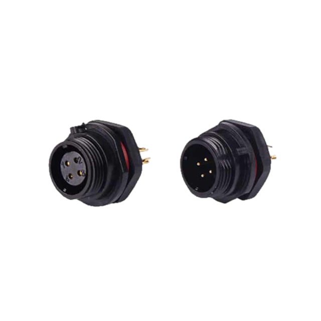

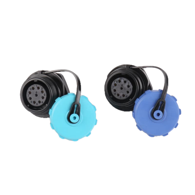
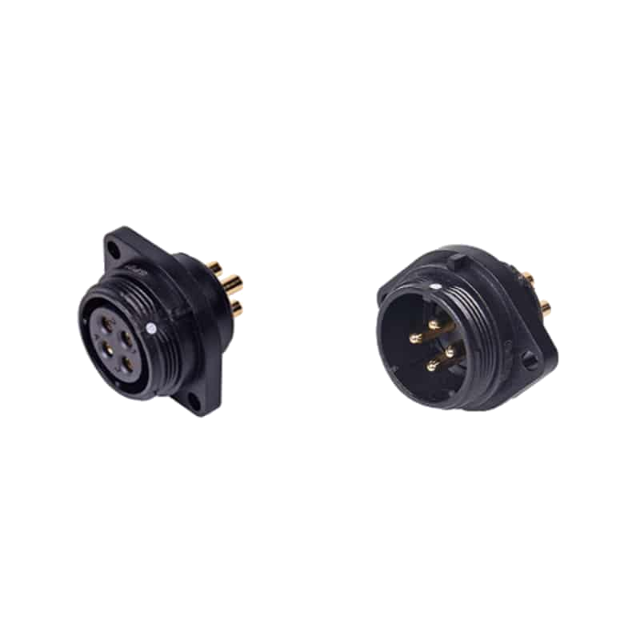

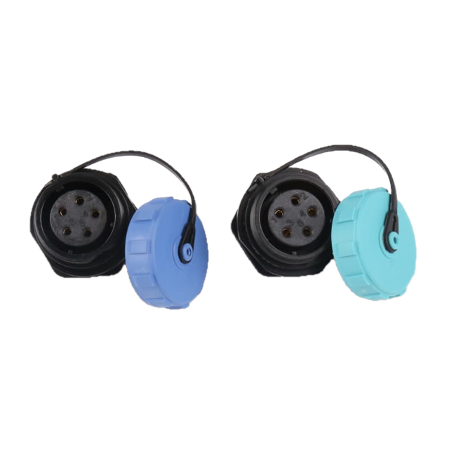


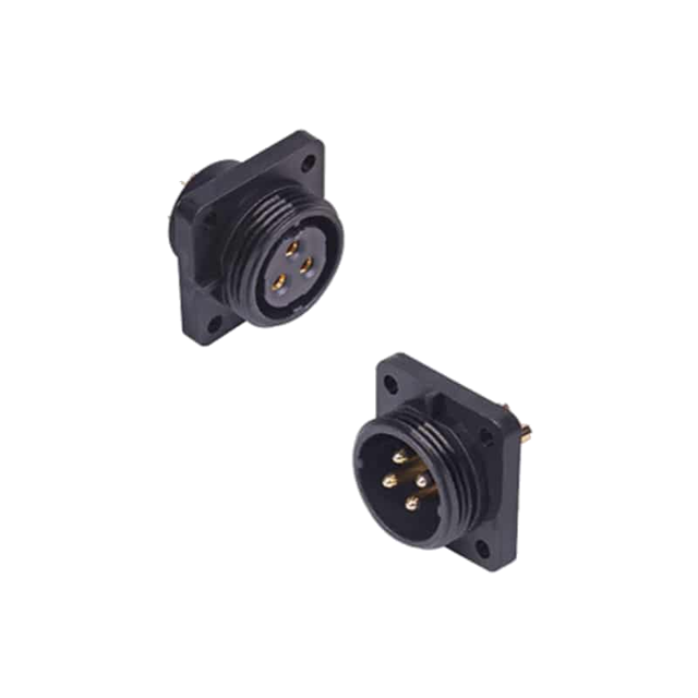
Circular connector groups
Cable connectors, panel mounts and angled exits.
TS-series connectors join harnesses to each other or to equipment panels. Choose the mounting form and cable direction, then match the mating halves.
Panel & Flange Mount Connectors range
Choose your panel & flange mount connectors
Panel connectors bring a detachable circular connection through an equipment wall. Rear-nut, two-hole and square-flange forms offer different fixing arrangements.
Models & specifications
Panel & Flange Mount Connectors: specifications and dimensions
Select a product to see its specifications, drawings and sizes.
Product selection
Choose the mount for your equipment panel.
Match the cut-out, panel thickness and fixing holes, then select the compatible cable half and contact layout.- 01Panel mount: Rear nut, two-hole flange or square flange
- 02Cut-out: Opening size, hole spacing and panel thickness
- 03Mating and wiring: Cable half, contact layout and rear terminal access
TS11PS/TS11PP Rear-Nut Panel Connectors
01 / Circular plug and socket
TS11PS/TS11PP Rear-Nut Panel Connectors
TS11PS and TS11PP mount at an enclosure wall with a rear retaining nut. Solder-terminal layouts have 2 to 5 contacts.
Product reference
- Product group
- Panel & Flange Mount Connectors
- Application
- Fit a TS11 connection through a panel where the retaining nut can be accessed from the rear.
Key specifications
- Product Type
- Rear-Nut Panel Connectors
- Models
- TS11PS (Panel Socket, Female), TS11PP (Panel Plug, Male)
- Mounting Style
- Rear-Nut Panel Mount
- Coupling Type
- Threaded
Product specifications
Construction and details

Panel mounting and connector dimensions
Confirm the mating interface, contact arrangement and mounting dimensions for the selected model.
Read the marked dimensions with the current model drawing; do not infer sizes by measuring the illustration.
Model specification tablesFurther specifications
- Shell Material
- PC, Nylon PA66
- Insert Material
- PPS
- Contact Material
- Brass with Gold Plating
- IP Rating
- IP68
- Operating Temperature
- -40°C to +85°C
- Mating Cycle
- 500 cycles
- Pin Counts Available
- Solder layouts: 2, 3, 4, 5.
- Termination
- Solder
- Panel cutout
- Ø11 mm; 9.9 mm across flats
- Maximum panel thickness
- 3.5 mm
- Panel mounting thread
- M11 × 1
Key features
- Rear-nut panel mountA retaining nut secures the connector body through the panel.
- Threaded couplingA threaded coupling secures the mating connection.
- Contact optionsSolder layouts: 2, 3, 4, 5.
TS13PS/TS13PP Rear-Nut Panel Connectors
02 / Circular plug and socket
TS13PS/TS13PP Rear-Nut Panel Connectors
TS13PS and TS13PP mount at an enclosure wall with a rear retaining nut. Solder-terminal layouts have 2, 3, 4, 5, 6, 7 or 9 contacts.
Product reference
- Product group
- Panel & Flange Mount Connectors
- Application
- Fit a TS13 connection through a panel where the retaining nut can be accessed from the rear.
Key specifications
- Series
- TS13 Series
- Models
- TS13PS (Panel Socket, Female), TS13PP (Panel Plug, Male)
- Mounting Style
- Rear-Nut Panel Mount
- Coupling Type
- Threaded
Product specifications
Construction and details

Panel mounting and connector dimensions
Confirm the mating interface, contact arrangement and mounting dimensions for the selected model.
Read the marked dimensions with the current model drawing; do not infer sizes by measuring the illustration.
Model specification tablesFurther specifications
- Shell Material
- PC, Nylon PA66
- Insert Material
- PPS
- Contact Material
- Brass with Gold Plating
- IP Rating
- IP68
- Operating Temperature
- -40°C to +85°C
- Mating Cycle
- 500 cycles
- Pin Counts Available
- Solder layouts: 2, 3, 4, 5, 6, 7, 9.
- Termination
- Solder
- Panel cutout
- Ø13 mm; 12.3 mm across flats
- Maximum panel thickness
- 3.5 mm
- Panel mounting thread
- M13 × 1
Key features
- Rear-nut panel mountA retaining nut secures the connector body through the panel.
- Threaded couplingA threaded coupling secures the mating connection.
- Contact optionsSolder layouts: 2, 3, 4, 5, 6, 7, 9.
TS17PS/TS17PP Rear-Nut Panel Connectors
03 / Circular plug and socket
TS17PS/TS17PP Rear-Nut Panel Connectors
TS17PS and TS17PP mount at an enclosure wall with a rear retaining nut. The TS17 range offers separate solder and crimp contact layouts.
Product reference
- Product group
- Panel & Flange Mount Connectors
- Application
- Fit a TS17 connection through a panel where the retaining nut can be accessed from the rear.
Key specifications
- Series
- TS17 Series
- Models
- TS17PS (Panel Socket, Female), TS17PP (Panel Plug, Male)
- Mounting Style
- Rear-Nut Panel Mount
- Coupling Type
- Threaded
Product specifications
Construction and details

Panel mounting and connector dimensions
Confirm the mating interface, contact arrangement and mounting dimensions for the selected model.
Read the marked dimensions with the current model drawing; do not infer sizes by measuring the illustration.
Model specification tablesFurther specifications
- Shell Material
- PC, Nylon PA66
- Insert Material
- PPS
- Contact Material
- Brass with Gold Plating
- IP Rating
- IP68
- Operating Temperature
- -40°C to +85°C
- Mating Cycle
- 500 cycles
- Pin Counts Available
- Solder layouts: 2, 3, 4, 5, 7, 9, 10. Crimp layouts: 2, 3, 4.
- Termination
- Solder or Crimp
- Panel cutout
- Ø17 mm; keyed profile
- Maximum panel thickness
- 3 mm
- Panel mounting thread
- M17 × 1
Key features
- Rear-nut panel mountA retaining nut secures the connector body through the panel.
- Threaded couplingA threaded coupling secures the mating connection.
- Contact optionsSolder layouts: 2, 3, 4, 5, 7, 9, 10. Crimp layouts: 2, 3, 4.
TS17FS/TS17FP Two-Hole Flange Connectors
04 / Circular plug and socket
TS17FS/TS17FP Two-Hole Flange Connectors
TS17FS and TS17FP mount to a panel through a two-hole flange. The TS17 range offers separate solder and crimp contact layouts.
Product reference
- Product group
- Panel & Flange Mount Connectors
- Application
- Mount a TS17 interface with two flange fasteners at the enclosure wall.
Key specifications
- Series
- TS17 Series
- Models
- TS17FS (Flange Panel Socket, Female), TS17FP (Flange Panel Plug, Male)
- Mounting Style
- 2-Hole Flange Mount
- Coupling Type
- Threaded
Product specifications
Construction and details

Panel mounting and connector dimensions
Confirm the mating interface, contact arrangement and mounting dimensions for the selected model.
Read the marked dimensions with the current model drawing; do not infer sizes by measuring the illustration.
Model specification tablesFurther specifications
- Shell Material
- PC, Nylon PA66
- Insert Material
- PPS
- Contact Material
- Brass with Gold Plating
- IP Rating
- IP68
- Operating Temperature
- -40°C to +85°C
- Mating Cycle
- 500 cycles
- Pin Counts Available
- Solder layouts: 2, 3, 4, 5, 7, 9, 10. Crimp layouts: 2, 3, 4.
- Termination
- Solder or Crimp
- Panel cutout
- Ø17 mm; two Ø3.6 mm fastening holes at 26 mm centers
Key features
- Two-hole flangeThe flange provides two fastener positions for panel mounting.
- Threaded couplingA threaded coupling secures the mating connection.
- Contact optionsSolder layouts: 2, 3, 4, 5, 7, 9, 10. Crimp layouts: 2, 3, 4.
TS17SS/TS17SP Square-Flange Connectors
05 / Circular plug and socket
TS17SS/TS17SP Square-Flange Connectors
TS17SS and TS17SP mount to a panel through a four-hole square flange. The TS17 range offers separate solder and crimp contact layouts.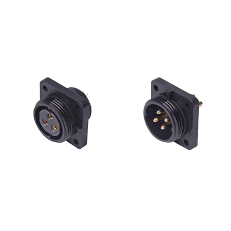
Product reference
- Product group
- Panel & Flange Mount Connectors
- Application
- Install a TS17 panel connection using a four-fastener square flange.
Key specifications
- Series
- TS17 Series
- Models
- TS17SS (Square Panel Socket, Female), TS17SP (Square Panel Plug, Male)
- Mounting Style
- 4-Hole Square Flange Mount
- Coupling Type
- Threaded
Product specifications
Construction and details

Panel mounting and connector dimensions
Confirm the mating interface, contact arrangement and mounting dimensions for the selected model.
Read the marked dimensions with the current model drawing; do not infer sizes by measuring the illustration.
Model specification tablesFurther specifications
- Shell Material
- PC, Nylon PA66
- Insert Material
- PPS
- Contact Material
- Brass with Gold Plating
- IP Rating
- IP68
- Operating Temperature
- -40°C to +85°C
- Mating Cycle
- 500 cycles
- Pin Counts Available
- Solder layouts: 2, 3, 4, 5, 7, 9, 10. Crimp layouts: 2, 3, 4.
- Termination
- Solder or Crimp
- Maximum panel thickness
- 3 mm
Key features
- Four-hole square flangeFour fastener positions secure the square flange to the panel.
- Threaded couplingA threaded coupling secures the mating connection.
- Contact optionsSolder layouts: 2, 3, 4, 5, 7, 9, 10. Crimp layouts: 2, 3, 4.
TS21PS/TS21PP Rear-Nut Panel Connectors
06 / Circular plug and socket
TS21PS/TS21PP Rear-Nut Panel Connectors
TS21PS and TS21PP mount at an enclosure wall with a rear retaining nut. The TS21 range offers separate solder and crimp contact layouts.
Product reference
- Product group
- Panel & Flange Mount Connectors
- Application
- Fit a TS21 connection through a panel where the retaining nut can be accessed from the rear.
Key specifications
- Product Type
- Rear-Nut Panel Connectors
- Models
- TS21PS (Panel Socket, Female), TS21PP (Panel Plug, Male)
- Mounting Style
- Rear-Nut Panel Mount
- Coupling Type
- Threaded
Product specifications
Construction and details

Panel mounting and connector dimensions
Confirm the mating interface, contact arrangement and mounting dimensions for the selected model.
Read the marked dimensions with the current model drawing; do not infer sizes by measuring the illustration.
Model specification tablesFurther specifications
- Shell Material
- PC, Nylon PA66
- Insert Material
- PPS
- Contact Material
- Brass with Gold Plating
- IP Rating
- IP68
- Operating Temperature
- -40°C to +85°C
- Mating Cycle
- 500 cycles
- Pin Counts Available
- Solder layouts: 2, 3, 4, 5, 5B, 5C, 7, 9, 12. Crimp layouts: 2, 3, 4, 5, 7, 7B, 8.
- Rated Current
- Up to 30A (Varies by pin count and termination)
- Termination
- Solder or Crimp
- Panel cutout
- Ø21 mm; 20.2 mm across flats
- Maximum panel thickness
- 3 mm
- Panel mounting thread
- M21 × 1
Key features
- Rear-nut panel mountA retaining nut secures the connector body through the panel.
- Threaded couplingA threaded coupling secures the mating connection.
- Contact optionsSolder layouts: 2, 3, 4, 5, 5B, 5C, 7, 9, 12. Crimp layouts: 2, 3, 4, 5, 7, 7B, 8.
TS21FS/TS21FP Two-Hole Flange Connectors
07 / Circular plug and socket
TS21FS/TS21FP Two-Hole Flange Connectors
TS21FS and TS21FP mount to a panel through a two-hole flange. The TS21 range offers separate solder and crimp contact layouts.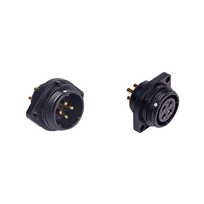
Product reference
- Product group
- Panel & Flange Mount Connectors
- Application
- Mount a TS21 interface with two flange fasteners at the enclosure wall.
Key specifications
- Series
- TS21 Series
- Models
- TS21FS (Flange Panel Socket, Female), TS21FP (Flange Panel Plug, Male)
- Mounting Style
- 2-Hole Flange Mount
- Coupling Type
- Threaded
Product specifications
Construction and details

Panel mounting and connector dimensions
Confirm the mating interface, contact arrangement and mounting dimensions for the selected model.
Read the marked dimensions with the current model drawing; do not infer sizes by measuring the illustration.
Model specification tablesFurther specifications
- Shell Material
- PC, Nylon PA66
- Insert Material
- PPS
- Contact Material
- Brass with Gold Plating
- IP Rating
- IP68
- Operating Temperature
- -40°C to +85°C
- Mating Cycle
- 500 cycles
- Pin Counts Available
- Solder layouts: 2, 3, 4, 5, 5B, 5C, 7, 9, 12. Crimp layouts: 2, 3, 4, 5, 7, 7B, 8.
- Rated Current
- Up to 30A (Varies by pin count and termination)
- Termination
- Solder or Crimp
- Panel cutout
- Ø21 mm; two Ø4 mm fastening holes at 31 mm centers
Key features
- Two-hole flangeThe flange provides two fastener positions for panel mounting.
- Threaded couplingA threaded coupling secures the mating connection.
- Contact optionsSolder layouts: 2, 3, 4, 5, 5B, 5C, 7, 9, 12. Crimp layouts: 2, 3, 4, 5, 7, 7B, 8.
TS21SS/TS21SP Square-Flange Connectors
08 / Circular plug and socket
TS21SS/TS21SP Square-Flange Connectors
TS21SS and TS21SP mount to a panel through a four-hole square flange. The TS21 range offers separate solder and crimp contact layouts.
Product reference
- Product group
- Panel & Flange Mount Connectors
- Application
- Install a TS21 panel connection using a four-fastener square flange.
Key specifications
- Series
- TS21 Series
- Models
- TS21SS (Square Panel Socket, Female), TS21SP (Square Panel Plug, Male)
- Mounting Style
- 4-Hole Square Flange Mount
- Coupling Type
- Threaded
Product specifications
Construction and details

Panel mounting and connector dimensions
Confirm the mating interface, contact arrangement and mounting dimensions for the selected model.
Read the marked dimensions with the current model drawing; do not infer sizes by measuring the illustration.
Model specification tablesFurther specifications
- Shell Material
- PC, Nylon PA66
- Insert Material
- PPS
- Contact Material
- Brass with Gold Plating
- IP Rating
- IP68
- Operating Temperature
- -40°C to +85°C
- Mating Cycle
- 500 cycles
- Pin Counts Available
- Solder layouts: 2, 3, 4, 5, 5B, 5C, 7, 9, 12. Crimp layouts: 2, 3, 4, 5, 7, 7B, 8.
- Rated Current
- Up to 30A (Varies by pin count and termination)
- Termination
- Solder or Crimp
- Panel cutout
- Ø21 mm; four Ø4 mm fastening holes on a 23 × 23 mm pattern
Key features
- Four-hole square flangeFour fastener positions secure the square flange to the panel.
- Threaded couplingA threaded coupling secures the mating connection.
- Contact optionsSolder layouts: 2, 3, 4, 5, 5B, 5C, 7, 9, 12. Crimp layouts: 2, 3, 4, 5, 7, 7B, 8.
TS29PS/TS29PP Rear-Nut Panel Connectors
09 / Circular plug and socket
TS29PS/TS29PP Rear-Nut Panel Connectors
TS29PS and TS29PP mount at an enclosure wall with a rear retaining nut. The TS29 range offers separate solder and crimp contact layouts.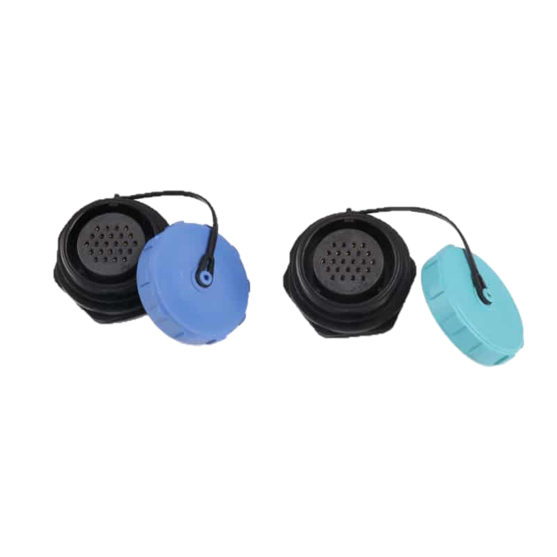
Product reference
- Product group
- Panel & Flange Mount Connectors
- Application
- Fit a TS29 connection through a panel where the retaining nut can be accessed from the rear.
Key specifications
- Series
- TS29 Series
- Models
- TS29PS (Panel Socket, Female), TS29PP (Panel Plug, Male)
- Mounting Style
- Rear-Nut Panel Mount
- Coupling Type
- Threaded
Product specifications
Construction and details

Panel mounting and connector dimensions
Confirm the mating interface, contact arrangement and mounting dimensions for the selected model.
Read the marked dimensions with the current model drawing; do not infer sizes by measuring the illustration.
Model specification tablesFurther specifications
- Shell Material
- PC, Nylon PA66
- Insert Material
- PPS
- Contact Material
- Brass with Gold Plating
- IP Rating
- IP68
- Operating Temperature
- -40°C to +85°C
- Mating Cycle
- 500 cycles
- Pin Counts Available
- Solder layouts: 2, 3, 4, 7, 8, 9, 10, 10B, 12, 16, 17, 20, 24, 26. Crimp layouts: 7, 12, 15, 19.
- Rated Current
- Up to 50A (Varies by pin count and termination)
- Termination
- Solder or Crimp
- Panel cutout
- Ø29.2 mm; 26.6 mm across flats
- Maximum panel thickness
- 2 mm
- Panel mounting thread
- M29 × 1.25
Key features
- Rear-nut panel mountA retaining nut secures the connector body through the panel.
- Threaded couplingA threaded coupling secures the mating connection.
- Contact optionsSolder layouts: 2, 3, 4, 7, 8, 9, 10, 10B, 12, 16, 17, 20, 24, 26. Crimp layouts: 7, 12, 15, 19.
TS29FS/TS29FP Two-Hole Flange Connectors
10 / Circular plug and socket
TS29FS/TS29FP Two-Hole Flange Connectors
TS29FS and TS29FP mount to a panel through a two-hole flange. The TS29 range offers separate solder and crimp contact layouts.
Product reference
- Product group
- Panel & Flange Mount Connectors
- Application
- Mount a TS29 interface with two flange fasteners at the enclosure wall.
Key specifications
- Series
- TS29 Series
- Models
- TS29FS (Flange Panel Socket, Female), TS29FP (Flange Panel Plug, Male)
- Mounting Style
- 2-Hole Flange Mount
- Coupling Type
- Threaded
Product specifications
Construction and details

Panel mounting and connector dimensions
Confirm the mating interface, contact arrangement and mounting dimensions for the selected model.
Read the marked dimensions with the current model drawing; do not infer sizes by measuring the illustration.
Model specification tablesFurther specifications
- Shell Material
- PC, Nylon PA66
- Insert Material
- PPS
- Contact Material
- Brass with Gold Plating
- IP Rating
- IP68
- Operating Temperature
- -40°C to +85°C
- Mating Cycle
- 500 cycles
- Pin Counts Available
- Solder layouts: 2, 3, 4, 7, 8, 9, 10, 10B, 12, 16, 17, 20, 24, 26. Crimp layouts: 7, 12, 15, 19.
- Rated Current
- Up to 50A (Varies by pin count and termination)
- Termination
- Solder or Crimp
- Panel cutout
- Ø28 mm; two Ø5 mm fastening holes at 45 mm centers
Key features
- Two-hole flangeThe flange provides two fastener positions for panel mounting.
- Threaded couplingA threaded coupling secures the mating connection.
- Contact optionsSolder layouts: 2, 3, 4, 7, 8, 9, 10, 10B, 12, 16, 17, 20, 24, 26. Crimp layouts: 7, 12, 15, 19.
TS29SS/TS29SP Square-Flange Connectors
11 / Circular plug and socket
TS29SS/TS29SP Square-Flange Connectors
TS29SS and TS29SP mount to a panel through a four-hole square flange. The TS29 range offers separate solder and crimp contact layouts.
Product reference
- Product group
- Panel & Flange Mount Connectors
- Application
- Install a TS29 panel connection using a four-fastener square flange.
Key specifications
- Series
- TS29 Series
- Models
- TS29SS (Square Panel Socket, Female), TS29SP (Square Panel Plug, Male)
- Mounting Style
- 4-Hole Square Flange Mount
- Coupling Type
- Threaded
Product specifications
Construction and details

Panel mounting and connector dimensions
Confirm the mating interface, contact arrangement and mounting dimensions for the selected model.
Read the marked dimensions with the current model drawing; do not infer sizes by measuring the illustration.
Model specification tablesFurther specifications
- Shell Material
- PC, Nylon PA66
- Insert Material
- PPS
- Contact Material
- Brass with Gold Plating
- IP Rating
- IP68
- Operating Temperature
- -40°C to +85°C
- Mating Cycle
- 500 cycles
- Pin Counts Available
- Solder layouts: 2, 3, 4, 7, 8, 9, 10, 10B, 12, 16, 17, 20, 24, 26. Crimp layouts: 7, 12, 15, 19.
- Rated Current
- Up to 50A (Varies by pin count and termination)
- Termination
- Solder or Crimp
- Panel cutout
- Ø28 mm; four Ø5 mm fastening holes on a 31 × 31 mm pattern
Key features
- Four-hole square flangeFour fastener positions secure the square flange to the panel.
- Threaded couplingA threaded coupling secures the mating connection.
- Contact optionsSolder layouts: 2, 3, 4, 7, 8, 9, 10, 10B, 12, 16, 17, 20, 24, 26. Crimp layouts: 7, 12, 15, 19.
Model specification tables
Model sizes and specifications
TS11PS/TS11PP Rear-Nut Panel Connectors
Panel & Flange Mount Connectors
TS11PS/TS11PP Rear-Nut Panel Connectors
Model specificationsTS11 — solder contact ratings
| Contact count | 2 | 3 | 4 | 5 |
|---|---|---|---|---|
| Male contact face view |  |  |  |  |
| Rated current(A) | 5 | 5 | 3 | 3 |
| Contact diameter(mm) | Φ1×2 | Φ1×3 | Φ0.7×4 | Φ0.7×5 |
| Rated voltage(AC.V) | 180 | 180 | 125 | 125 |
| Test voltage(AC.V) 1min | 1000 | 1000 | 1000 | 1000 |
| Contact resistance (mΩ) | 5 | 5 | 10 | 10 |
| Wire size (mm2/AWG) | ≤0.75/18 | ≤0.75/18 | ≤0.5/20 | ≤0.5/20 |
TS13PS/TS13PP Rear-Nut Panel Connectors
Panel & Flange Mount Connectors
TS13PS/TS13PP Rear-Nut Panel Connectors
Model specificationsTS13 — solder contact ratings
| Contact count | 2 | 3 | 4 | 5 | 6 | 7 | 9 |
|---|---|---|---|---|---|---|---|
| Male contact face view | | | | |  |  |  |
| Rated current(A) | 13 | 13 | 5 | 5 | 5 | 5 | 3 |
| Contact diameter(mm) | Φ1.6×2 | Φ1.6×3 | Φ1×4 | Φ1×5 | Φ1×6 | Φ1×7 | Φ0.7×9 |
| Rated voltage(AC.V) | 250 | 250 | 200 | 180 | 125 | 125 | 125 |
| Test voltage(AC.V) 1min | 1500 | 1500 | 1500 | 1000 | 1000 | 1000 | 1000 |
| Contact resistance (mΩ) | 2.5 | 2.5 | 5 | 5 | 5 | 5 | 10 |
| Wire size (mm2/AWG) | ≤2/14 | ≤2/14 | ≤0.75/18 | ≤0.75/18 | ≤0.75/18 | ≤0.75/18 | ≤0.5/20 |
TS17PS/TS17PP Rear-Nut Panel Connectors
Panel & Flange Mount Connectors
TS17PS/TS17PP Rear-Nut Panel Connectors
Model specificationsTS17 — solder contact ratings
| Contact count | 2 | 3 | 4 | 5 | 7 | 9 | 10 |
|---|---|---|---|---|---|---|---|
| Male contact face view | | | | | | |  |
| Rated current(A) | 10 | 10 | 5 | 5 | 5 | 5 | 5 |
| Contact diameter(mm) | Φ1.5×2 | Φ1.5×3 | Φ1×4 | Φ1×5 | Φ1×7 | Φ1×9 | Φ1×10 |
| Rated voltage(AC.V) | 500 | 500 | 500 | 500 | 400 | 400 | 400 |
| Test voltage(AC.V) 1min | 1500 | 1500 | 1500 | 1000 | 1200 | 1200 | 1200 |
| Contact resistance (mΩ) | 2.5 | 2.5 | 5 | 5 | 5 | 5 | 10 |
| Wire size (mm2/AWG) | ≤2/14 | ≤2/14 | ≤0.75/18 | ≤0.75/18 | ≤0.75/18 | ≤0.75/18 | ≤0.7/ |
Model specificationsTS17 — crimp contact ratings
| Contact count | 2 | 3 | 4 |
|---|---|---|---|
| Male contact face view | |  |  |
| Rated current(A) | 10 | 10 | 5 |
| Contact diameter(mm) | Φ1.5×2 | Φ1.5×3 | Φ1×4 |
| Rated voltage(AC.V) | 500 | 500 | 500 |
| Test voltage(AC.V) 1min | 1500 | 1500 | 1500 |
| Contact resistance (mΩ) | 2.5 | 2.5 | 5 |
TS17FS/TS17FP Two-Hole Flange Connectors
Panel & Flange Mount Connectors
TS17FS/TS17FP Two-Hole Flange Connectors
Model specificationsTS17 — solder contact ratings
| Contact count | 2 | 3 | 4 | 5 | 7 | 9 | 10 |
|---|---|---|---|---|---|---|---|
| Male contact face view | | | | | | | |
| Rated current(A) | 10 | 10 | 5 | 5 | 5 | 5 | 5 |
| Contact diameter(mm) | Φ1.5×2 | Φ1.5×3 | Φ1×4 | Φ1×5 | Φ1×7 | Φ1×9 | Φ1×10 |
| Rated voltage(AC.V) | 500 | 500 | 500 | 500 | 400 | 400 | 400 |
| Test voltage(AC.V) 1min | 1500 | 1500 | 1500 | 1000 | 1200 | 1200 | 1200 |
| Contact resistance (mΩ) | 2.5 | 2.5 | 5 | 5 | 5 | 5 | 10 |
| Wire size (mm2/AWG) | ≤2/14 | ≤2/14 | ≤0.75/18 | ≤0.75/18 | ≤0.75/18 | ≤0.75/18 | ≤0.7/ |
Model specificationsTS17 — crimp contact ratings
| Contact count | 2 | 3 | 4 |
|---|---|---|---|
| Male contact face view | | | |
| Rated current(A) | 10 | 10 | 5 |
| Contact diameter(mm) | Φ1.5×2 | Φ1.5×3 | Φ1×4 |
| Rated voltage(AC.V) | 500 | 500 | 500 |
| Test voltage(AC.V) 1min | 1500 | 1500 | 1500 |
| Contact resistance (mΩ) | 2.5 | 2.5 | 5 |
TS17SS/TS17SP Square-Flange Connectors
Panel & Flange Mount Connectors
TS17SS/TS17SP Square-Flange Connectors
Model specificationsTS17 — solder contact ratings
| Contact count | 2 | 3 | 4 | 5 | 7 | 9 | 10 |
|---|---|---|---|---|---|---|---|
| Male contact face view | | | | | | | |
| Rated current(A) | 10 | 10 | 5 | 5 | 5 | 5 | 5 |
| Contact diameter(mm) | Φ1.5×2 | Φ1.5×3 | Φ1×4 | Φ1×5 | Φ1×7 | Φ1×9 | Φ1×10 |
| Rated voltage(AC.V) | 500 | 500 | 500 | 500 | 400 | 400 | 400 |
| Test voltage(AC.V) 1min | 1500 | 1500 | 1500 | 1000 | 1200 | 1200 | 1200 |
| Contact resistance (mΩ) | 2.5 | 2.5 | 5 | 5 | 5 | 5 | 10 |
| Wire size (mm2/AWG) | ≤2/14 | ≤2/14 | ≤0.75/18 | ≤0.75/18 | ≤0.75/18 | ≤0.75/18 | ≤0.7/ |
Model specificationsTS17 — crimp contact ratings
| Contact count | 2 | 3 | 4 |
|---|---|---|---|
| Male contact face view | | | |
| Rated current(A) | 10 | 10 | 5 |
| Contact diameter(mm) | Φ1.5×2 | Φ1.5×3 | Φ1×4 |
| Rated voltage(AC.V) | 500 | 500 | 500 |
| Test voltage(AC.V) 1min | 1500 | 1500 | 1500 |
| Contact resistance (mΩ) | 2.5 | 2.5 | 5 |
TS21PS/TS21PP Rear-Nut Panel Connectors
Panel & Flange Mount Connectors
TS21PS/TS21PP Rear-Nut Panel Connectors
Model specificationsTS21 — solder contact ratings
| Contact count | 2 | 3 | 4 | 5 | 5B | 5C | 7 | 9 | 12 |
|---|---|---|---|---|---|---|---|---|---|
| Male contact face view |  |  |  |  |  |  |  |  |  |
| Rated current(A) | 30 | 30 | 30 | 30 | 30 5 | 15 | 15 | 5 | 5 |
| Contact diameter(mm) | Φ3×2 | Φ3×3 | Φ3×4 | Φ3×5 | Φ3×2 Φ1×3 | Φ2×5 | Φ2×7 | Φ1×9 | Φ1×12 |
| Rated voltage(AC.V) | 500 | 500 | 500 | 500 | 500 | 500 | 500 | 500 | 500 |
| Test voltage(AC.V) 1min | 1500 | 1500 | 1500 | 1500 | 1500 | 1500 | 1500 | 1500 | 1500 |
| Contact resistance (mΩ) | 1 | 1 | 1 | 1 | 1 5 | 2.5 | 2.5 | 5 | 5 |
| Wire size (mm2/AWG) | ≤4/11 | ≤4/11 | ≤4/11 | ≤4/11 | ≤0.75/18 ≤4/11 | ≤2/14 | ≤2/14 | ≤0.75/18 | ≤0.7/18 |
Model specificationsTS21 — crimp contact ratings
| Contact count | 2 | 3 | 4 | 5 | 7 | 7B | 8 |
|---|---|---|---|---|---|---|---|
| Male contact face view | | |  | |  |  |  |
| Rated current(A) | 25 | 25 | 25 | 10 | 10 | 5 | 5 |
| Contact diameter(mm) | Φ2.5×2 | Φ2.5×3 | Φ2.5×4 | Φ1.5×5 | Φ1.5×7 | Φ1×7 | Φ1×8 |
| Rated voltage(AC.V) | 500 | 500 | 500 | 500 | 500 | 400 | 400 |
| Test voltage(AC.V) 1min | 1500 | 1500 | 1500 | 1500 | 1500 | 1200 | 1200 |
| Contact resistance (mΩ) | 1 | 1 | 1 | 2.5 | 2.5 | 5 | 5 |
TS21FS/TS21FP Two-Hole Flange Connectors
Panel & Flange Mount Connectors
TS21FS/TS21FP Two-Hole Flange Connectors
Model specificationsTS21 — solder contact ratings
| Contact count | 2 | 3 | 4 | 5 | 5B | 5C | 7 | 9 | 12 |
|---|---|---|---|---|---|---|---|---|---|
| Male contact face view | | | | | | | | | |
| Rated current(A) | 30 | 30 | 30 | 30 | 30 5 | 15 | 15 | 5 | 5 |
| Contact diameter(mm) | Φ3×2 | Φ3×3 | Φ3×4 | Φ3×5 | Φ3×2 Φ1×3 | Φ2×5 | Φ2×7 | Φ1×9 | Φ1×12 |
| Rated voltage(AC.V) | 500 | 500 | 500 | 500 | 500 | 500 | 500 | 500 | 500 |
| Test voltage(AC.V) 1min | 1500 | 1500 | 1500 | 1500 | 1500 | 1500 | 1500 | 1500 | 1500 |
| Contact resistance (mΩ) | 1 | 1 | 1 | 1 | 1 5 | 2.5 | 2.5 | 5 | 5 |
| Wire size (mm2/AWG) | ≤4/11 | ≤4/11 | ≤4/11 | ≤4/11 | ≤0.75/18 ≤4/11 | ≤2/14 | ≤2/14 | ≤0.75/18 | ≤0.7/18 |
Model specificationsTS21 — crimp contact ratings
| Contact count | 2 | 3 | 4 | 5 | 7 | 7B | 8 |
|---|---|---|---|---|---|---|---|
| Male contact face view | | | | | | | |
| Rated current(A) | 25 | 25 | 25 | 10 | 10 | 5 | 5 |
| Contact diameter(mm) | Φ2.5×2 | Φ2.5×3 | Φ2.5×4 | Φ1.5×5 | Φ1.5×7 | Φ1×7 | Φ1×8 |
| Rated voltage(AC.V) | 500 | 500 | 500 | 500 | 500 | 400 | 400 |
| Test voltage(AC.V) 1min | 1500 | 1500 | 1500 | 1500 | 1500 | 1200 | 1200 |
| Contact resistance (mΩ) | 1 | 1 | 1 | 2.5 | 2.5 | 5 | 5 |
TS21SS/TS21SP Square-Flange Connectors
Panel & Flange Mount Connectors
TS21SS/TS21SP Square-Flange Connectors
Model specificationsTS21 — solder contact ratings
| Contact count | 2 | 3 | 4 | 5 | 5B | 5C | 7 | 9 | 12 |
|---|---|---|---|---|---|---|---|---|---|
| Male contact face view | | | | | | | | | |
| Rated current(A) | 30 | 30 | 30 | 30 | 30 5 | 15 | 15 | 5 | 5 |
| Contact diameter(mm) | Φ3×2 | Φ3×3 | Φ3×4 | Φ3×5 | Φ3×2 Φ1×3 | Φ2×5 | Φ2×7 | Φ1×9 | Φ1×12 |
| Rated voltage(AC.V) | 500 | 500 | 500 | 500 | 500 | 500 | 500 | 500 | 500 |
| Test voltage(AC.V) 1min | 1500 | 1500 | 1500 | 1500 | 1500 | 1500 | 1500 | 1500 | 1500 |
| Contact resistance (mΩ) | 1 | 1 | 1 | 1 | 1 5 | 2.5 | 2.5 | 5 | 5 |
| Wire size (mm2/AWG) | ≤4/11 | ≤4/11 | ≤4/11 | ≤4/11 | ≤0.75/18 ≤4/11 | ≤2/14 | ≤2/14 | ≤0.75/18 | ≤0.7/18 |
Model specificationsTS21 — crimp contact ratings
| Contact count | 2 | 3 | 4 | 5 | 7 | 7B | 8 |
|---|---|---|---|---|---|---|---|
| Male contact face view | | | | | | | |
| Rated current(A) | 25 | 25 | 25 | 10 | 10 | 5 | 5 |
| Contact diameter(mm) | Φ2.5×2 | Φ2.5×3 | Φ2.5×4 | Φ1.5×5 | Φ1.5×7 | Φ1×7 | Φ1×8 |
| Rated voltage(AC.V) | 500 | 500 | 500 | 500 | 500 | 400 | 400 |
| Test voltage(AC.V) 1min | 1500 | 1500 | 1500 | 1500 | 1500 | 1200 | 1200 |
| Contact resistance (mΩ) | 1 | 1 | 1 | 2.5 | 2.5 | 5 | 5 |
TS29PS/TS29PP Rear-Nut Panel Connectors
Panel & Flange Mount Connectors
TS29PS/TS29PP Rear-Nut Panel Connectors
Model specificationsTS29 — solder contact ratings
| Contact count | 2 | 3 | 4 | 7 | 8 | 9 | 10 | 10B | 12 | 16 | 17 | 20 | 24 | 26 |
|---|---|---|---|---|---|---|---|---|---|---|---|---|---|---|
| Male contact face view |  |  |  |  |  |  |  |  |  |  |  |  |  |  |
| Rated current(A) | 50 | 50 | 25 | 25 | 25 | 25 5 | 25 | 10 | 10 | 10 | 10 | 5 | 5 | 5 |
| Contact diameter(mm) | Φ3.5×2 | Φ3.5×3 | Φ2.5×4 | Φ2.5×7 | Φ2.5×8 | Φ2.5×4 Φ1×5 | Φ2.5×10 | Φ1.5×10 | Φ1.5×12 | Φ1.5×16 | Φ1.5×17 | Φ1×20 | Φ1×24 | Φ1×26 |
| Rated voltage(AC.V) | 500 | 500 | 500 | 500 | 500 | 500 | 500 | 500 | 500 | 500 | 500 | 400 | 400 | 400 |
| Test voltage(AC.V) 1min | 1500 | 1500 | 1500 | 1500 | 1500 | 1500 | 1500 | 1500 | 1500 | 1500 | 1500 | 1200 | 1200 | 1200 |
| Contact resistance (mΩ) | 0.5 | 0.5 | 1 | 1 | 1 | 1 5 | 1 | 2.5 | 2.5 | 2.5 | 2.5 | 5 | 5 | 5 |
| Wire size (mm2/AWG) | ≤10/7 | ≤10/7 | ≤4/11 | ≤4/11 | ≤4/11 | ≤4/11 ≤0.75/18 | ≤4/11 | ≤2/14 | ≤2/14 | ≤2/14 | ≤2/14 | ≤0.75/18 | ≤0.75/18 | ≤0.75/18 |
Model specificationsTS29 — crimp contact ratings
| Contact count | 7 | 12 | 15 | 19 |
|---|---|---|---|---|
| Male contact face view |  |  |  |  |
| Rated current(A) | 25 | 10 | 5 | 5 |
| Contact diameter(mm) | Φ2.5×7 | Φ1.5×12 | Φ1×15 | Φ1×19 |
| Rated voltage(AC.V) | 500 | 500 | 400 | 400 |
| Test voltage(AC.V) 1min | 1500 | 1500 | 1200 | 1200 |
| Contact resistance (mΩ) | 1 | 2.5 | 5 | 5 |
TS29FS/TS29FP Two-Hole Flange Connectors
Panel & Flange Mount Connectors
TS29FS/TS29FP Two-Hole Flange Connectors
Model specificationsTS29 — solder contact ratings
| Contact count | 2 | 3 | 4 | 7 | 8 | 9 | 10 | 10B | 12 | 16 | 17 | 20 | 24 | 26 |
|---|---|---|---|---|---|---|---|---|---|---|---|---|---|---|
| Male contact face view | | | | | | | | | | | | | | |
| Rated current(A) | 50 | 50 | 25 | 25 | 25 | 25 5 | 25 | 10 | 10 | 10 | 10 | 5 | 5 | 5 |
| Contact diameter(mm) | Φ3.5×2 | Φ3.5×3 | Φ2.5×4 | Φ2.5×7 | Φ2.5×8 | Φ2.5×4 Φ1×5 | Φ2.5×10 | Φ1.5×10 | Φ1.5×12 | Φ1.5×16 | Φ1.5×17 | Φ1×20 | Φ1×24 | Φ1×26 |
| Rated voltage(AC.V) | 500 | 500 | 500 | 500 | 500 | 500 | 500 | 500 | 500 | 500 | 500 | 400 | 400 | 400 |
| Test voltage(AC.V) 1min | 1500 | 1500 | 1500 | 1500 | 1500 | 1500 | 1500 | 1500 | 1500 | 1500 | 1500 | 1200 | 1200 | 1200 |
| Contact resistance (mΩ) | 0.5 | 0.5 | 1 | 1 | 1 | 1 5 | 1 | 2.5 | 2.5 | 2.5 | 2.5 | 5 | 5 | 5 |
| Wire size (mm2/AWG) | ≤10/7 | ≤10/7 | ≤4/11 | ≤4/11 | ≤4/11 | ≤4/11 ≤0.75/18 | ≤4/11 | ≤2/14 | ≤2/14 | ≤2/14 | ≤2/14 | ≤0.75/18 | ≤0.75/18 | ≤0.75/18 |
Model specificationsTS29 — crimp contact ratings
| Contact count | 7 | 12 | 15 | 19 |
|---|---|---|---|---|
| Male contact face view | | | | |
| Rated current(A) | 25 | 10 | 5 | 5 |
| Contact diameter(mm) | Φ2.5×7 | Φ1.5×12 | Φ1×15 | Φ1×19 |
| Rated voltage(AC.V) | 500 | 500 | 400 | 400 |
| Test voltage(AC.V) 1min | 1500 | 1500 | 1200 | 1200 |
| Contact resistance (mΩ) | 1 | 2.5 | 5 | 5 |
TS29SS/TS29SP Square-Flange Connectors
Panel & Flange Mount Connectors
TS29SS/TS29SP Square-Flange Connectors
Model specificationsTS29 — solder contact ratings
| Contact count | 2 | 3 | 4 | 7 | 8 | 9 | 10 | 10B | 12 | 16 | 17 | 20 | 24 | 26 |
|---|---|---|---|---|---|---|---|---|---|---|---|---|---|---|
| Male contact face view | | | | | | | | | | | | | | |
| Rated current(A) | 50 | 50 | 25 | 25 | 25 | 25 5 | 25 | 10 | 10 | 10 | 10 | 5 | 5 | 5 |
| Contact diameter(mm) | Φ3.5×2 | Φ3.5×3 | Φ2.5×4 | Φ2.5×7 | Φ2.5×8 | Φ2.5×4 Φ1×5 | Φ2.5×10 | Φ1.5×10 | Φ1.5×12 | Φ1.5×16 | Φ1.5×17 | Φ1×20 | Φ1×24 | Φ1×26 |
| Rated voltage(AC.V) | 500 | 500 | 500 | 500 | 500 | 500 | 500 | 500 | 500 | 500 | 500 | 400 | 400 | 400 |
| Test voltage(AC.V) 1min | 1500 | 1500 | 1500 | 1500 | 1500 | 1500 | 1500 | 1500 | 1500 | 1500 | 1500 | 1200 | 1200 | 1200 |
| Contact resistance (mΩ) | 0.5 | 0.5 | 1 | 1 | 1 | 1 5 | 1 | 2.5 | 2.5 | 2.5 | 2.5 | 5 | 5 | 5 |
| Wire size (mm2/AWG) | ≤10/7 | ≤10/7 | ≤4/11 | ≤4/11 | ≤4/11 | ≤4/11 ≤0.75/18 | ≤4/11 | ≤2/14 | ≤2/14 | ≤2/14 | ≤2/14 | ≤0.75/18 | ≤0.75/18 | ≤0.75/18 |
Model specificationsTS29 — crimp contact ratings
| Contact count | 7 | 12 | 15 | 19 |
|---|---|---|---|---|
| Male contact face view | | | | |
| Rated current(A) | 25 | 10 | 5 | 5 |
| Contact diameter(mm) | Φ2.5×7 | Φ1.5×12 | Φ1×15 | Φ1×19 |
| Rated voltage(AC.V) | 500 | 500 | 400 | 400 |
| Test voltage(AC.V) 1min | 1500 | 1500 | 1200 | 1200 |
| Contact resistance (mΩ) | 1 | 2.5 | 5 | 5 |
Product comparison
Rear-nut and flange mounting dimensions.
Compare the panel opening, fixing-hole pattern, rear clearance and contact arrangement.| Product | Construction | Use when | Check first | Review |
|---|---|---|---|---|
| TS11PS/TS11PP Rear-Nut Panel Connectors | Panel & Flange Mount Connectors | Fit a TS11 connection through a panel where the retaining nut can be accessed from the rear. |
| View specifications |
| TS13PS/TS13PP Rear-Nut Panel Connectors | Panel & Flange Mount Connectors | Fit a TS13 connection through a panel where the retaining nut can be accessed from the rear. |
| View specifications |
| TS17PS/TS17PP Rear-Nut Panel Connectors | Panel & Flange Mount Connectors | Fit a TS17 connection through a panel where the retaining nut can be accessed from the rear. |
| View specifications |
| TS17FS/TS17FP Two-Hole Flange Connectors | Panel & Flange Mount Connectors | Mount a TS17 interface with two flange fasteners at the enclosure wall. |
| View specifications |
| TS17SS/TS17SP Square-Flange Connectors | Panel & Flange Mount Connectors | Install a TS17 panel connection using a four-fastener square flange. |
| View specifications |
| TS21PS/TS21PP Rear-Nut Panel Connectors | Panel & Flange Mount Connectors | Fit a TS21 connection through a panel where the retaining nut can be accessed from the rear. |
| View specifications |
| TS21FS/TS21FP Two-Hole Flange Connectors | Panel & Flange Mount Connectors | Mount a TS21 interface with two flange fasteners at the enclosure wall. |
| View specifications |
| TS21SS/TS21SP Square-Flange Connectors | Panel & Flange Mount Connectors | Install a TS21 panel connection using a four-fastener square flange. |
| View specifications |
| TS29PS/TS29PP Rear-Nut Panel Connectors | Panel & Flange Mount Connectors | Fit a TS29 connection through a panel where the retaining nut can be accessed from the rear. |
| View specifications |
| TS29FS/TS29FP Two-Hole Flange Connectors | Panel & Flange Mount Connectors | Mount a TS29 interface with two flange fasteners at the enclosure wall. |
| View specifications |
| TS29SS/TS29SP Square-Flange Connectors | Panel & Flange Mount Connectors | Install a TS29 panel connection using a four-fastener square flange. |
| View specifications |
Need help matching an existing part? Send us its model name or a photo.
Selection checks
Choose the right model
Panel connectors bring a detachable circular connection through an equipment wall. Rear-nut, two-hole and square-flange forms offer different fixing arrangements.
- Panel mountRear nut, two-hole flange or square flange
- Cut-outOpening size, hole spacing and panel thickness
- Mating and wiringCable half, contact layout and rear terminal access
Product support
Need a model recommendation or a quote?
Send a model name, a photo or a short question. We can help with product selection, samples and pricing. Share any of the details below that you already have.
Request product support- TS marking or panel photoSend the TS marking or a photo showing the connector on the equipment panel.
- Preferred mounting formChoose a rear nut, two-hole flange or square flange if your panel design already specifies one.
- Panel cut-out and thicknessShare the panel opening, fixing-hole pattern and wall thickness if a drawing is available.
- Contact layout and electrical loadA contact-face photo plus the circuit voltage and current helps identify the required insert.
- Rear wiring clearanceDescribe the space behind the panel for the terminals, wires and mounting fasteners.
Panel & Flange Mount Connectors FAQ
Product questions
Find answers about fit, wiring and product differences.
Panel & Flange Mount Connectors
01Can I exchange a rear-nut connector for a flange form?
The panel opening and fixing method can differ. Compare the mounting drawings, hole pattern and available space before changing the form.
02What needs clearance behind the panel?
Allow room for the connector body, rear nut or fasteners, terminals and conductor bends. This space is separate from the clearance needed to mate the cable plug outside.
TS11PS/TS11PP Rear-Nut Panel Connectors
TS11PS/TS11PP Rear-Nut Panel Connectors
01What cable connector mates with TS11PS/TS11PP?
The female TS11PS mates with a matching male TS11CP cable plug. The male TS11PP mates with a matching female TS11CS cable socket. Select the same contact layout on both sides.
02Are all TS11 contact layouts rated at 5 A?
The 2- and 3-contact solder layouts are rated at 5 A and 180 V AC. The 4- and 5-contact layouts are rated at 3 A and 125 V AC.
03What wire sizes fit the TS11 solder contacts?
The 2- and 3-contact layouts accept up to 0.75 mm² conductors. The 4- and 5-contact layouts accept up to 0.5 mm².
04What panel opening does TS11PS/TS11PP need?
The panel cutout is Ø11 mm with 9.9 mm across the flats. Maximum panel thickness is 3.5 mm, and the retaining thread is M11 × 1.
TS13PS/TS13PP Rear-Nut Panel Connectors
TS13PS/TS13PP Rear-Nut Panel Connectors
01What cable connector mates with TS13PS/TS13PP?
The female TS13PS mates with a matching male TS13CP cable plug. The male TS13PP mates with a matching female TS13CS cable socket. Select the same contact layout on both sides.
02Which TS13 layouts have the 13 A rating?
The 2- and 3-contact solder layouts are rated at 13 A. The 4-, 5-, 6- and 7-contact layouts are 5 A; the 9-contact layout is 3 A.
03Do all TS13 contact layouts use the same wire size?
No. The 2- and 3-contact layouts accept up to 2 mm² conductors; the 4- through 7-contact layouts accept up to 0.75 mm²; the 9-contact layout accepts up to 0.5 mm².
04What panel opening does TS13PS/TS13PP need?
The panel cutout is Ø13 mm with 12.3 mm across the flats. Maximum panel thickness is 3.5 mm, and the retaining thread is M13 × 1.
TS17PS/TS17PP Rear-Nut Panel Connectors
TS17PS/TS17PP Rear-Nut Panel Connectors
01What cable connector mates with TS17PS/TS17PP?
The female TS17PS mates with a matching male TS17CP cable plug. The male TS17PP mates with a matching female TS17CS cable socket. Select the same contact layout on both sides.
02Is every TS17 layout rated at 500 V AC?
The 2-, 3-, 4- and 5-contact solder layouts are rated at 500 V AC. The 7-, 9- and 10-contact solder layouts are 400 V AC. The 2-, 3- and 4-contact crimp layouts are 500 V AC.
03Can I order a 7-contact TS17 with crimp terminals?
The 7-contact option is a solder layout. Crimp options cover 2, 3 and 4 contacts. The 2- and 3-contact layouts are rated at 10 A; the other layouts are 5 A.
04What panel opening does TS17PS/TS17PP need?
The panel cutout is Ø17 mm with a keyed profile. Maximum panel thickness is 3 mm, and the retaining thread is M17 × 1.
TS17FS/TS17FP Two-Hole Flange Connectors
TS17FS/TS17FP Two-Hole Flange Connectors
01What cable connector mates with TS17FS/TS17FP?
The female TS17FS mates with a matching male TS17CP cable plug. The male TS17FP mates with a matching female TS17CS cable socket. Select the same contact layout on both sides.
02Is every TS17 layout rated at 500 V AC?
The 2-, 3-, 4- and 5-contact solder layouts are rated at 500 V AC. The 7-, 9- and 10-contact solder layouts are 400 V AC. The 2-, 3- and 4-contact crimp layouts are 500 V AC.
03Can I order a 7-contact TS17 with crimp terminals?
The 7-contact option is a solder layout. Crimp options cover 2, 3 and 4 contacts. The 2- and 3-contact layouts are rated at 10 A; the other layouts are 5 A.
04What is the TS17FS/TS17FP panel hole pattern?
A Ø17 mm central opening with two Ø3.6 mm fastening holes at 26 mm centers. These are panel drilling dimensions; the holes in the connector flange may be smaller.
TS17SS/TS17SP Square-Flange Connectors
TS17SS/TS17SP Square-Flange Connectors
01What cable connector mates with TS17SS/TS17SP?
The female TS17SS mates with a matching male TS17CP cable plug. The male TS17SP mates with a matching female TS17CS cable socket. Select the same contact layout on both sides.
02Is every TS17 layout rated at 500 V AC?
The 2-, 3-, 4- and 5-contact solder layouts are rated at 500 V AC. The 7-, 9- and 10-contact solder layouts are 400 V AC. The 2-, 3- and 4-contact crimp layouts are 500 V AC.
03Can I order a 7-contact TS17 with crimp terminals?
The 7-contact option is a solder layout. Crimp options cover 2, 3 and 4 contacts. The 2- and 3-contact layouts are rated at 10 A; the other layouts are 5 A.
04What panel thickness fits TS17SS/SP?
The maximum panel thickness is 3 mm. The four-hole flange requires its own drilling pattern; it is different from the TS17 two-hole flange.
TS21PS/TS21PP Rear-Nut Panel Connectors
TS21PS/TS21PP Rear-Nut Panel Connectors
01What cable connector mates with TS21PS/TS21PP?
The female TS21PS mates with a matching male TS21CP cable plug. The male TS21PP mates with a matching female TS21CS cable socket. Select the same contact layout on both sides.
02Are TS21 solder and crimp contacts both rated at 30 A?
No. The 2-, 3-, 4- and 5-contact solder layouts are rated at 30 A. The 2-, 3- and 4-contact crimp layouts are 25 A. Other layouts have their own lower or mixed contact ratings.
03How do TS21 5, 5B and 5C solder layouts differ?
The 5 layout has five 3 mm contacts rated at 30 A. The 5B layout combines two 3 mm contacts with three 1 mm contacts, rated at 30 A and 5 A respectively. The 5C layout has five 2 mm contacts rated at 15 A.
04What panel opening does TS21PS/TS21PP need?
The panel cutout is Ø21 mm with 20.2 mm across the flats. Maximum panel thickness is 3 mm, and the retaining thread is M21 × 1.
TS21FS/TS21FP Two-Hole Flange Connectors
TS21FS/TS21FP Two-Hole Flange Connectors
01What cable connector mates with TS21FS/TS21FP?
The female TS21FS mates with a matching male TS21CP cable plug. The male TS21FP mates with a matching female TS21CS cable socket. Select the same contact layout on both sides.
02Are TS21 solder and crimp contacts both rated at 30 A?
No. The 2-, 3-, 4- and 5-contact solder layouts are rated at 30 A. The 2-, 3- and 4-contact crimp layouts are 25 A. Other layouts have their own lower or mixed contact ratings.
03How do TS21 5, 5B and 5C solder layouts differ?
The 5 layout has five 3 mm contacts rated at 30 A. The 5B layout combines two 3 mm contacts with three 1 mm contacts, rated at 30 A and 5 A respectively. The 5C layout has five 2 mm contacts rated at 15 A.
04What is the TS21FS/TS21FP panel hole pattern?
A Ø21 mm central opening with two Ø4 mm fastening holes at 31 mm centers. These are panel drilling dimensions; the holes in the connector flange may be smaller.
TS21SS/TS21SP Square-Flange Connectors
TS21SS/TS21SP Square-Flange Connectors
01What cable connector mates with TS21SS/TS21SP?
The female TS21SS mates with a matching male TS21CP cable plug. The male TS21SP mates with a matching female TS21CS cable socket. Select the same contact layout on both sides.
02Are TS21 solder and crimp contacts both rated at 30 A?
No. The 2-, 3-, 4- and 5-contact solder layouts are rated at 30 A. The 2-, 3- and 4-contact crimp layouts are 25 A. Other layouts have their own lower or mixed contact ratings.
03How do TS21 5, 5B and 5C solder layouts differ?
The 5 layout has five 3 mm contacts rated at 30 A. The 5B layout combines two 3 mm contacts with three 1 mm contacts, rated at 30 A and 5 A respectively. The 5C layout has five 2 mm contacts rated at 15 A.
04What is the TS21SS/TS21SP panel hole pattern?
A Ø21 mm central opening and four Ø4 mm fastening holes on a 23 × 23 mm square pattern.
TS29PS/TS29PP Rear-Nut Panel Connectors
TS29PS/TS29PP Rear-Nut Panel Connectors
01What cable connector mates with TS29PS/TS29PP?
The female TS29PS mates with a matching male TS29CP cable plug. The male TS29PP mates with a matching female TS29CS cable socket. Select the same contact layout on both sides.
02Which TS29 layouts are rated at 50 A?
The 2- and 3-contact solder layouts are rated at 50 A. The crimp range starts with a 7-contact, 25 A layout; its 12-contact version is 10 A and its 15- and 19-contact versions are 5 A.
03What is the difference between TS29 10 and 10B?
Both are 10-contact solder layouts. The 10 layout uses 2.5 mm contacts rated at 25 A. The 10B layout uses 1.5 mm contacts rated at 10 A.
04What panel opening does TS29PS/TS29PP need?
The panel cutout is Ø29.2 mm with 26.6 mm across the flats. Maximum panel thickness is 2 mm, and the retaining thread is M29 × 1.25.
TS29FS/TS29FP Two-Hole Flange Connectors
TS29FS/TS29FP Two-Hole Flange Connectors
01What cable connector mates with TS29FS/TS29FP?
The female TS29FS mates with a matching male TS29CP cable plug. The male TS29FP mates with a matching female TS29CS cable socket. Select the same contact layout on both sides.
02Which TS29 layouts are rated at 50 A?
The 2- and 3-contact solder layouts are rated at 50 A. The crimp range starts with a 7-contact, 25 A layout; its 12-contact version is 10 A and its 15- and 19-contact versions are 5 A.
03What is the difference between TS29 10 and 10B?
Both are 10-contact solder layouts. The 10 layout uses 2.5 mm contacts rated at 25 A. The 10B layout uses 1.5 mm contacts rated at 10 A.
04What is the TS29FS/TS29FP panel hole pattern?
A Ø28 mm central opening with two Ø5 mm fastening holes at 45 mm centers. These are panel drilling dimensions; the holes in the connector flange may be smaller.
TS29SS/TS29SP Square-Flange Connectors
TS29SS/TS29SP Square-Flange Connectors
01What cable connector mates with TS29SS/TS29SP?
The female TS29SS mates with a matching male TS29CP cable plug. The male TS29SP mates with a matching female TS29CS cable socket. Select the same contact layout on both sides.
02Which TS29 layouts are rated at 50 A?
The 2- and 3-contact solder layouts are rated at 50 A. The crimp range starts with a 7-contact, 25 A layout; its 12-contact version is 10 A and its 15- and 19-contact versions are 5 A.
03What is the difference between TS29 10 and 10B?
Both are 10-contact solder layouts. The 10 layout uses 2.5 mm contacts rated at 25 A. The 10B layout uses 1.5 mm contacts rated at 10 A.
04What is the TS29SS/TS29SP panel hole pattern?
A Ø28 mm central opening and four Ø5 mm fastening holes on a 31 × 31 mm square pattern.