
Aviation Connectors / Angled cable exit
Right-Angle Circular Connectors
TS17, TS21 and TS29 NP/NS connectors turn the cable exit alongside the equipment.
- Exit direction: Cable orientation after mating and local clearance
- Mating pair: TS17, TS21 or TS29 NP/NS contact arrangement
- Cable bend: Cable outside diameter and room for the bend
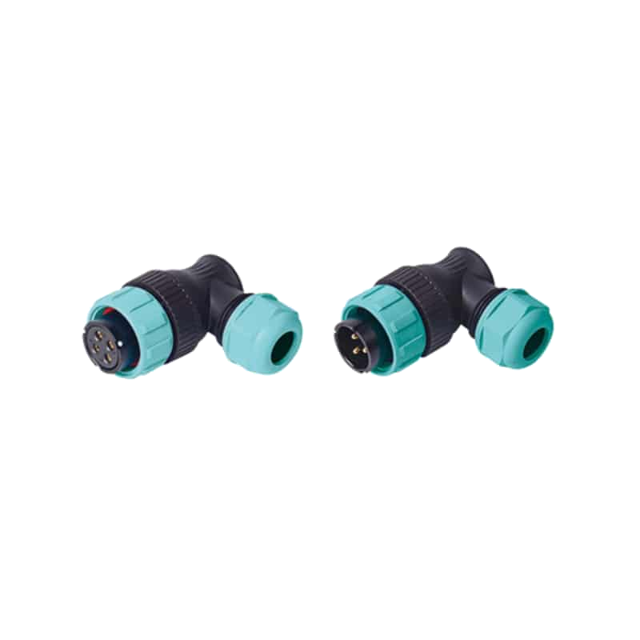


Circular connector groups
Cable connectors, panel mounts and angled exits.
TS-series connectors join harnesses to each other or to equipment panels. Choose the mounting form and cable direction, then match the mating halves.
Right-Angle Circular Connectors range
Choose your right-angle circular connectors
TS17, TS21 and TS29 NP/NS right-angle connectors turn the cable exit alongside the equipment. They suit cable routes where a straight body would project too far.
Models & specifications
Right-Angle Circular Connectors: specifications and dimensions
Select a product to see its specifications, drawings and sizes.
Product selection
Choose the angle and clearance for the cable exit.
Check where the cable will point when the connector is mated, then allow space for the cable bend and locking parts.- 01Exit direction: Cable orientation after mating and local clearance
- 02Mating pair: TS17, TS21 or TS29 NP/NS contact arrangement
- 03Cable bend: Cable outside diameter and room for the bend
TS17NP/TS17NS Right-Angle Cable Connectors
01 / Circular plug and socket
TS17NP/TS17NS Right-Angle Cable Connectors
TS17NP and TS17NS turn the cable exit through 90 degrees. The TS17 range offers separate solder and crimp contact layouts.
Product reference
- Product group
- Right-Angle Circular Connectors
- Application
- Route the cable at 90 degrees to a TS17 mating interface where a straight cable exit would occupy the wrong space.
Key specifications
- Series
- TS17 Series
- Models
- TS17NP (Corner Cable Plug, Male), TS17NS (Corner Cable Socket, Female)
- Angle
- 90-Degree
- Coupling Type
- Threaded
Product specifications
Construction and details

Angled connector and mounting envelope
Confirm the mating interface, contact arrangement and mounting dimensions for the selected model.
Read the marked dimensions with the current model drawing; do not infer sizes by measuring the illustration.
Model specification tablesFurther specifications
- Shell Material
- PC, Nylon PA66
- Insert Material
- PPS
- Contact Material
- Brass with Gold Plating
- IP Rating
- IP68
- Operating Temperature
- -40°C to +85°C
- Mating Cycle
- 500 cycles
- Pin Counts Available
- Solder layouts: 2, 3, 4, 5, 7, 9, 10. Crimp layouts: 2, 3, 4.
- Termination
- Solder or Crimp
- Cable outside diameter
- 6–10 mm
- Body length
- 48 mm
- Body height
- 40 mm
Key features
- 90-degree cable exitThe corner body changes the cable-exit direction relative to the mating axis.
- Threaded couplingA threaded coupling secures the mating connection.
- Contact optionsSolder layouts: 2, 3, 4, 5, 7, 9, 10. Crimp layouts: 2, 3, 4.
TS21NP/TS21NS Right-Angle Cable Connectors
02 / Circular plug and socket
TS21NP/TS21NS Right-Angle Cable Connectors
TS21NP and TS21NS turn the cable exit through 90 degrees. The TS21 range offers separate solder and crimp contact layouts.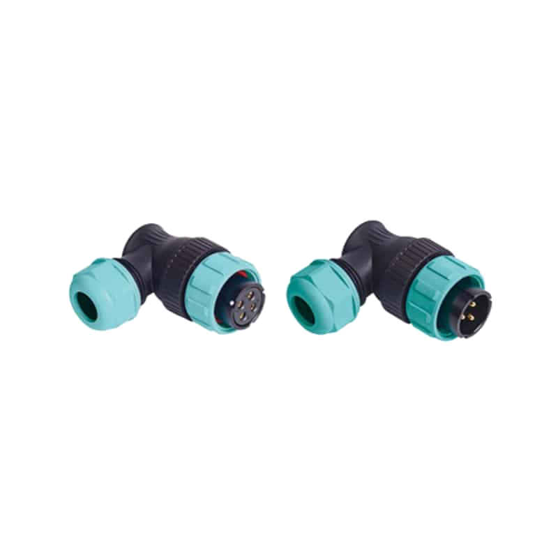
Product reference
- Product group
- Right-Angle Circular Connectors
- Application
- Route the cable at 90 degrees to a TS21 mating interface where a straight cable exit would occupy the wrong space.
Key specifications
- Series
- TS21 Series
- Models
- TS21NP (Corner Cable Plug, Male), TS21NS (Corner Cable Socket, Female)
- Angle
- 90-Degree
- Coupling Type
- Threaded
Product specifications
Construction and details

Angled connector and mounting envelope
Confirm the mating interface, contact arrangement and mounting dimensions for the selected model.
Read the marked dimensions with the current model drawing; do not infer sizes by measuring the illustration.
Model specification tablesFurther specifications
- Shell Material
- PC, Nylon PA66
- Insert Material
- PPS
- Contact Material
- Brass with Gold Plating
- IP Rating
- IP68
- Operating Temperature
- -40°C to +85°C
- Mating Cycle
- 500 cycles
- Pin Counts Available
- Solder layouts: 2, 3, 4, 5, 5B, 5C, 7, 9, 12. Crimp layouts: 2, 3, 4, 5, 7, 7B, 8.
- Termination
- Solder or Crimp
- Cable outside diameter
- 7–12 mm; S version: 4.5–7 mm
- Body length
- 57 mm
- Body height
- 51 mm
Key features
- 90-degree cable exitThe corner body changes the cable-exit direction relative to the mating axis.
- Threaded couplingA threaded coupling secures the mating connection.
- Contact optionsSolder layouts: 2, 3, 4, 5, 5B, 5C, 7, 9, 12. Crimp layouts: 2, 3, 4, 5, 7, 7B, 8.
TS29NP/TS29NS Right-Angle Cable Connectors
03 / Circular plug and socket
TS29NP/TS29NS Right-Angle Cable Connectors
TS29NP and TS29NS turn the cable exit through 90 degrees. The TS29 range offers separate solder and crimp contact layouts.
Product reference
- Product group
- Right-Angle Circular Connectors
- Application
- Route the cable at 90 degrees to a TS29 mating interface where a straight cable exit would occupy the wrong space.
Key specifications
- Series
- TS29 Series
- Models
- TS29NP (Corner Cable Plug, Male), TS29NS (Corner Cable Socket, Female)
- Angle
- 90-Degree
- Coupling Type
- Threaded
Product specifications
Construction and details

Angled connector and mounting envelope
Confirm the mating interface, contact arrangement and mounting dimensions for the selected model.
Read the marked dimensions with the current model drawing; do not infer sizes by measuring the illustration.
Model specification tablesFurther specifications
- Shell Material
- PC, Nylon PA66
- Insert Material
- PPS
- Contact Material
- Brass with Gold Plating
- IP Rating
- IP68
- Operating Temperature
- -40°C to +85°C
- Mating Cycle
- 500 cycles
- Pin Counts Available
- Solder layouts: 2, 3, 4, 7, 8, 9, 10, 10B, 12, 16, 17, 20, 24, 26. Crimp layouts: 7, 12, 15, 19.
- Termination
- Solder or Crimp
- Cable outside diameter
- 13–16 mm
- Body length
- 62 mm
- Body height
- 55 mm
Key features
- 90-degree cable exitThe corner body changes the cable-exit direction relative to the mating axis.
- Threaded couplingA threaded coupling secures the mating connection.
- Contact optionsSolder layouts: 2, 3, 4, 7, 8, 9, 10, 10B, 12, 16, 17, 20, 24, 26. Crimp layouts: 7, 12, 15, 19.
Model specification tables
Model sizes and specifications
TS17NP/TS17NS Right-Angle Cable Connectors
Right-Angle Circular Connectors
TS17NP/TS17NS Right-Angle Cable Connectors
Model specificationsTS17 — solder contact ratings
| Contact count | 2 | 3 | 4 | 5 | 7 | 9 | 10 |
|---|---|---|---|---|---|---|---|
| Male contact face view |  |  |  |  |  |  |  |
| Rated current(A) | 10 | 10 | 5 | 5 | 5 | 5 | 5 |
| Contact diameter(mm) | Φ1.5×2 | Φ1.5×3 | Φ1×4 | Φ1×5 | Φ1×7 | Φ1×9 | Φ1×10 |
| Rated voltage(AC.V) | 500 | 500 | 500 | 500 | 400 | 400 | 400 |
| Test voltage(AC.V) 1min | 1500 | 1500 | 1500 | 1000 | 1200 | 1200 | 1200 |
| Contact resistance (mΩ) | 2.5 | 2.5 | 5 | 5 | 5 | 5 | 10 |
| Wire size (mm2/AWG) | ≤2/14 | ≤2/14 | ≤0.75/18 | ≤0.75/18 | ≤0.75/18 | ≤0.75/18 | ≤0.7/ |
Model specificationsTS17 — crimp contact ratings
| Contact count | 2 | 3 | 4 |
|---|---|---|---|
| Male contact face view | |  |  |
| Rated current(A) | 10 | 10 | 5 |
| Contact diameter(mm) | Φ1.5×2 | Φ1.5×3 | Φ1×4 |
| Rated voltage(AC.V) | 500 | 500 | 500 |
| Test voltage(AC.V) 1min | 1500 | 1500 | 1500 |
| Contact resistance (mΩ) | 2.5 | 2.5 | 5 |
TS21NP/TS21NS Right-Angle Cable Connectors
Right-Angle Circular Connectors
TS21NP/TS21NS Right-Angle Cable Connectors
Model specificationsTS21 — solder contact ratings
| Contact count | 2 | 3 | 4 | 5 | 5B | 5C | 7 | 9 | 12 |
|---|---|---|---|---|---|---|---|---|---|
| Male contact face view |  |  |  |  |  |  |  |  |  |
| Rated current(A) | 30 | 30 | 30 | 30 | 30 5 | 15 | 15 | 5 | 5 |
| Contact diameter(mm) | Φ3×2 | Φ3×3 | Φ3×4 | Φ3×5 | Φ3×2 Φ1×3 | Φ2×5 | Φ2×7 | Φ1×9 | Φ1×12 |
| Rated voltage(AC.V) | 500 | 500 | 500 | 500 | 500 | 500 | 500 | 500 | 500 |
| Test voltage(AC.V) 1min | 1500 | 1500 | 1500 | 1500 | 1500 | 1500 | 1500 | 1500 | 1500 |
| Contact resistance (mΩ) | 1 | 1 | 1 | 1 | 1 5 | 2.5 | 2.5 | 5 | 5 |
| Wire size (mm2/AWG) | ≤4/11 | ≤4/11 | ≤4/11 | ≤4/11 | ≤0.75/18 ≤4/11 | ≤2/14 | ≤2/14 | ≤0.75/18 | ≤0.7/18 |
Model specificationsTS21 — crimp contact ratings
| Contact count | 2 | 3 | 4 | 5 | 7 | 7B | 8 |
|---|---|---|---|---|---|---|---|
| Male contact face view | | |  | |  |  |  |
| Rated current(A) | 25 | 25 | 25 | 10 | 10 | 5 | 5 |
| Contact diameter(mm) | Φ2.5×2 | Φ2.5×3 | Φ2.5×4 | Φ1.5×5 | Φ1.5×7 | Φ1×7 | Φ1×8 |
| Rated voltage(AC.V) | 500 | 500 | 500 | 500 | 500 | 400 | 400 |
| Test voltage(AC.V) 1min | 1500 | 1500 | 1500 | 1500 | 1500 | 1200 | 1200 |
| Contact resistance (mΩ) | 1 | 1 | 1 | 2.5 | 2.5 | 5 | 5 |
TS29NP/TS29NS Right-Angle Cable Connectors
Right-Angle Circular Connectors
TS29NP/TS29NS Right-Angle Cable Connectors
Model specificationsTS29 — solder contact ratings
| Contact count | 2 | 3 | 4 | 7 | 8 | 9 | 10 | 10B | 12 | 16 | 17 | 20 | 24 | 26 |
|---|---|---|---|---|---|---|---|---|---|---|---|---|---|---|
| Male contact face view |  |  |  |  |  |  |  |  |  |  |  |  |  |  |
| Rated current(A) | 50 | 50 | 25 | 25 | 25 | 25 5 | 25 | 10 | 10 | 10 | 10 | 5 | 5 | 5 |
| Contact diameter(mm) | Φ3.5×2 | Φ3.5×3 | Φ2.5×4 | Φ2.5×7 | Φ2.5×8 | Φ2.5×4 Φ1×5 | Φ2.5×10 | Φ1.5×10 | Φ1.5×12 | Φ1.5×16 | Φ1.5×17 | Φ1×20 | Φ1×24 | Φ1×26 |
| Rated voltage(AC.V) | 500 | 500 | 500 | 500 | 500 | 500 | 500 | 500 | 500 | 500 | 500 | 400 | 400 | 400 |
| Test voltage(AC.V) 1min | 1500 | 1500 | 1500 | 1500 | 1500 | 1500 | 1500 | 1500 | 1500 | 1500 | 1500 | 1200 | 1200 | 1200 |
| Contact resistance (mΩ) | 0.5 | 0.5 | 1 | 1 | 1 | 1 5 | 1 | 2.5 | 2.5 | 2.5 | 2.5 | 5 | 5 | 5 |
| Wire size (mm2/AWG) | ≤10/7 | ≤10/7 | ≤4/11 | ≤4/11 | ≤4/11 | ≤4/11 ≤0.75/18 | ≤4/11 | ≤2/14 | ≤2/14 | ≤2/14 | ≤2/14 | ≤0.75/18 | ≤0.75/18 | ≤0.75/18 |
Model specificationsTS29 — crimp contact ratings
| Contact count | 7 | 12 | 15 | 19 |
|---|---|---|---|---|
| Male contact face view |  |  |  |  |
| Rated current(A) | 25 | 10 | 5 | 5 |
| Contact diameter(mm) | Φ2.5×7 | Φ1.5×12 | Φ1×15 | Φ1×19 |
| Rated voltage(AC.V) | 500 | 500 | 400 | 400 |
| Test voltage(AC.V) 1min | 1500 | 1500 | 1200 | 1200 |
| Contact resistance (mΩ) | 1 | 2.5 | 5 | 5 |
Product comparison
Right-angle sizes and exit clearances.
Compare body dimensions, exit direction, contact layout and cable range.| Product | Construction | Use when | Check first | Review |
|---|---|---|---|---|
| TS17NP/TS17NS Right-Angle Cable Connectors | Right-Angle Circular Connectors | Route the cable at 90 degrees to a TS17 mating interface where a straight cable exit would occupy the wrong space. |
| View specifications |
| TS21NP/TS21NS Right-Angle Cable Connectors | Right-Angle Circular Connectors | Route the cable at 90 degrees to a TS21 mating interface where a straight cable exit would occupy the wrong space. |
| View specifications |
| TS29NP/TS29NS Right-Angle Cable Connectors | Right-Angle Circular Connectors | Route the cable at 90 degrees to a TS29 mating interface where a straight cable exit would occupy the wrong space. |
| View specifications |
Need help matching an existing part? Send us its model name or a photo.
Selection checks
Choose the right model
TS17, TS21 and TS29 NP/NS right-angle connectors turn the cable exit alongside the equipment. They suit cable routes where a straight body would project too far.
- Exit directionCable orientation after mating and local clearance
- Mating pairTS17, TS21 or TS29 NP/NS contact arrangement
- Cable bendCable outside diameter and room for the bend
Product support
Need a model recommendation or a quote?
Send a model name, a photo or a short question. We can help with product selection, samples and pricing. Share any of the details below that you already have.
Request product support- Connector model or installation photoSend the model or a photo showing where the angled connector will fit.
- Required cable exit directionShow which way the cable should leave the connector when it is mated.
- Contact layout and electrical loadA contact-face photo plus the circuit voltage and current helps identify the required insert.
- Cable diameterShare the cable-jacket diameter or cable reference if known.
- Available spaceA photo or approximate clearance around the connector helps check the angled body and cable bend.
Right-Angle Circular Connectors FAQ
Product questions
Find answers about fit, wiring and product differences.
Right-Angle Circular Connectors
01Will a right-angle connector always reduce installation space?
It reduces straight projection but needs room to the side for the body and cable bend. Compare both dimensions with the installation space.
02Can the cable exit point in any direction?
Do not assume it can rotate freely. Check the keying, mating orientation and any permitted adjustment for the chosen connector.
TS17NP/TS17NS Right-Angle Cable Connectors
TS17NP/TS17NS Right-Angle Cable Connectors
01Which bodies mate with TS17NP and TS17NS?
TS17NP mates with a matching female TS17PS panel socket or TS17RS cable socket. TS17NS mates with a matching male TS17PP panel plug or TS17RP cable plug. Their 90-degree bodies change the cable exit direction.
02Is every TS17 layout rated at 500 V AC?
The 2-, 3-, 4- and 5-contact solder layouts are rated at 500 V AC. The 7-, 9- and 10-contact solder layouts are 400 V AC. The 2-, 3- and 4-contact crimp layouts are 500 V AC.
03Can I order a 7-contact TS17 with crimp terminals?
The 7-contact option is a solder layout. Crimp options cover 2, 3 and 4 contacts. The 2- and 3-contact layouts are rated at 10 A; the other layouts are 5 A.
04How much space does the TS17NP/TS17NS body need?
The right-angle body is 48 mm long and 40 mm high. Its cable outside-diameter range is 6–10 mm. Additional space is needed for the cable bend beyond the gland.
TS21NP/TS21NS Right-Angle Cable Connectors
TS21NP/TS21NS Right-Angle Cable Connectors
01Which bodies mate with TS21NP and TS21NS?
TS21NP mates with a matching female TS21PS panel socket or TS21RS cable socket. TS21NS mates with a matching male TS21PP panel plug or TS21RP cable plug. Their 90-degree bodies change the cable exit direction.
02Are TS21 solder and crimp contacts both rated at 30 A?
No. The 2-, 3-, 4- and 5-contact solder layouts are rated at 30 A. The 2-, 3- and 4-contact crimp layouts are 25 A. Other layouts have their own lower or mixed contact ratings.
03How do TS21 5, 5B and 5C solder layouts differ?
The 5 layout has five 3 mm contacts rated at 30 A. The 5B layout combines two 3 mm contacts with three 1 mm contacts, rated at 30 A and 5 A respectively. The 5C layout has five 2 mm contacts rated at 15 A.
04How much space does the TS21NP/TS21NS body need?
The right-angle body is 57 mm long and 51 mm high. Its cable outside-diameter range is 7–12 mm; S version: 4.5–7 mm. Additional space is needed for the cable bend beyond the gland.
TS29NP/TS29NS Right-Angle Cable Connectors
TS29NP/TS29NS Right-Angle Cable Connectors
01Which bodies mate with TS29NP and TS29NS?
TS29NP mates with a matching female TS29PS panel socket or TS29RS cable socket. TS29NS mates with a matching male TS29PP panel plug or TS29RP cable plug. Their 90-degree bodies change the cable exit direction.
02Which TS29 layouts are rated at 50 A?
The 2- and 3-contact solder layouts are rated at 50 A. The crimp range starts with a 7-contact, 25 A layout; its 12-contact version is 10 A and its 15- and 19-contact versions are 5 A.
03What is the difference between TS29 10 and 10B?
Both are 10-contact solder layouts. The 10 layout uses 2.5 mm contacts rated at 25 A. The 10B layout uses 1.5 mm contacts rated at 10 A.
04How much space does the TS29NP/TS29NS body need?
The right-angle body is 62 mm long and 55 mm high. Its cable outside-diameter range is 13–16 mm. Additional space is needed for the cable bend beyond the gland.