

Use a gland with metal conduits only when it is documented as a conduit fitting for the exact construction and enclosure entry. I select the conduit termination first. A conventional cable gland seals and retains a cable jacket; that does not establish suitability for rigid tube, a bare flexible spiral or jacketed flexible metal conduit. Verify attachment, entry sealing and protective bonding separately. Electromagnetic-compatibility (EMC) duties need their own evidence too.
Key takeaways
- Identify whether the enclosure receives a cable, rigid conduit, flexible metal conduit or a purpose-built transition assembly.
- Match the fitting to the conduit standard, type, trade size or OD range, end preparation and entry thread.
- Keep conduit attachment, enclosure sealing, protective bonding and EMC acceptance as separate functions.
- Support and align rigid conduit; control motion, bend and fatigue at flexible conduit terminations.
- Accept the installed assembly with the product instruction and project test limits, not a generic torque or resistance value.
Decide when to use a gland with metal conduits
A cable gland receives a cable directly and seals, retains or anchors a defined cable layer. A conduit fitting connects conduit to another conduit, an enclosure or a transition part. Conductors or cables run inside the conduit. Catalogues may call either product a “gland,” so I identify the physical interface before using the name to select a part.
Conduit systems used to protect and manage insulated conductors or cables fall within IEC 61386-1:2008+A1:2017. Complete cable glands fall within IEC 62444:2010. The two product scopes are different, so an ordinary cable clamping range is not a conduit-fitting range.
| Wiring route at the enclosure | Component to specify | Interface that controls selection |
|---|---|---|
| Cable or cord enters directly | Cable gland or cord grip | Finished cable OD, jacket, seal and retention range |
| Threaded rigid metal conduit enters | Rigid-conduit connector or hub | Conduit thread, fitting thread, seating and bonding arrangement |
| Plain-end rigid tube enters | Listed or documented compression/set-screw fitting | Tube OD, wall/type, insertion depth and retention mechanism |
| Bare flexible metal conduit enters | Connector designed for that flexible conduit | Spiral/profile, trade size or OD, ferrule and grip geometry |
| Jacketed flexible metal conduit enters | Connector for that jacketed conduit system | Jacket OD and material, metal core, seal and grip interfaces |
| Flexible conduit changes to rigid conduit or tubing | Purpose-built transition coupling | Exact construction and size at both ends |
| Cable leaves the end of conduit before entering equipment | Separate conduit termination and cable-entry design | Edge protection, support, cable seal and enclosure entry |
Use the liquid-tight cord-grip and conduit-fitting comparison when deciding whether the enclosure entry receives a cable directly or terminates a conduit.
For a North American product route, conduit, tubing and cable fittings may fall within the stated scope of UL 514B. The selected fitting still needs the applicable listing or certification record, marking and installation instruction for its precise conduit and entry. A broad standard title does not qualify an unlisted field combination.
Record the conduit construction before choosing a fitting
Begin with the conduit manufacturer’s identity, standard, type and size. “Metal conduit” is not enough because rigid, pliable, flexible, interlocked, corrugated and jacketed products present different end geometry and mechanical behavior.
For every conduit end, collect:
- Manufacturer, product family, part number and drawing or catalogue revision.
- Applicable conduit standard and classification.
- Trade size or nominal size plus actual OD limits where the fitting uses OD.
- Metal construction, wall or spiral profile and protective finish.
- Thread designation, pitch, taper or parallel form when the conduit is threaded.
- Jacket material, OD limits and permitted preparation for a jacketed flexible conduit.
- Minimum bend radius, movement class, pull load and support requirements.
- Indoor, outdoor, wet, washdown, chemical, temperature, UV and corrosion duty.
- Protective-conductor and EMC role assigned to the conduit system.
- Required product listing, declaration or test evidence for the jurisdiction.
I keep the diameter definition tied to the conduit construction. Outside diameter (OD) over a spiral crest, the outermost part of its winding, differs from jacket OD on liquidtight conduit. A nominal trade size also does not authorize another construction. Match the fitting’s documented conduit family and size table line by line.
I inspect the conduit end before assembly. Check roundness and cut quality, threads and jacket, then crushed convolutions—the successive bends or windings in flexible conduit. Look for corrosion and contamination too. If preparation falls outside the fitting instructions, cut back to a sound section and prepare it correctly. Extra tightening cannot repair the end geometry.
Match the conduit, fitting and enclosure interfaces
For each conduit type and size, check the compatible fitting and enclosure-entry arrangement. The following details determine whether the parts can grip, seal and conduct as required:
- Conduit standard, type, nominal or trade size, actual OD limits where applicable, wall or spiral profile, finish, and bare or jacketed construction.
- Connector part number, drawing revision, represented conduit family, component order, permitted orientation, and any replaceable seal or ferrule identity.
- Thread standard, size, pitch, gender, usable length, gauging requirement, enclosure hole or hub, wall and coating stack, seating land, and tool access.
- Preparation dimensions, insertion depth, gap, witness condition, tightening value or screw sequence from the exact product instruction.
- Support, alignment, first-bend, motion, temperature, chemical, UV, corrosion, and ingress requirements for the installed route.
- Protective-bonding test method, points, and acceptance limit, plus the EMC frequency range and measurement method when EMC performance is specified.
- Applicable listing, declaration, test report, marking, replacement-parts rule, and approved substitution limits.
Before assembly, match the conduit and fitting part numbers, component count, markings and end geometry to their instructions. Different spirals, jackets, threads or ferrules can need different connectors even when the parts look alike.
Select and install a fitting for rigid metal conduit
Rigid metal conduit needs a connector that matches its exact end: threaded, plain compression, set-screw or another documented system. For projects based on the IEC 61386 series, the particular requirements for rigid conduit systems are in IEC 61386-21:2021, used with IEC 61386-1. The conduit classification and fitting evidence must represent the assembly being installed.
For a threaded rigid conduit, copy the full thread designation from both drawings. Outside diameters for conduits and dimensional requirements for associated-fitting threads follow the system in IEC 60423:2007. NPT, IEC metric and other thread families are not interchangeable on the strength of a similar measured diameter. Use the thread-conversion reference when two interfaces use different standards; an approved adaptor needs its own drawing, sealing path and certification scope.
For a plain-end connection, I identify where the fitting grips. Its ferrule, compression ring or set screw must suit the conduit wall and finish. A ferrule is the sleeve used to support or grip the end. Record insertion depth, end stop and screw or nut sequence, plus the permitted completion condition. A torque from another body size or material does not define this joint.
Prepare the rigid end with the specified tool. Keep the cut square, remove sharp internal edges by the permitted method and clean away swarf, the chips left by cutting. Preserve the required finish and wall. I check that conductors cannot touch a sharp edge during pulling or vibration and fit any required bushing or throat component protecting the opening.
I align rigid conduit with the enclosure entry before final tightening. Its fitting should not pull a misaligned run into place or support an otherwise unsupported length. Transfer conduit weight and external loads to the structure through brackets and supports specified by the project and system instructions.
At the enclosure, stage the prepared rigid end on its own bracket and check its axis against the connector before insertion. Keep the end unforced while comparing the documented end form and entry stack.

The visible gap is a staging position. Confirm the actual thread or plain-end geometry, fitting pairing, usable engagement and permitted load from the approved drawings and instructions before completing the joint.
At a clearance-hole enclosure entry, include the connector shoulder, face seal, wall, coating, washers and locknut. At a tapped hub, compare the complete male and female thread, usable depth, seating face and rear clearance. The fitting must reach its intended seating condition without bottoming or running out of usable thread.
Select and install a fitting for flexible metal conduit
Flexible metal conduit needs a connector designed to retain its particular spiral or jacketed construction while preserving the permitted bend and movement outside the fitting. For projects based on the IEC 61386 series, the particular requirements for flexible conduit systems are in IEC 61386-23:2021, used with IEC 61386-1.
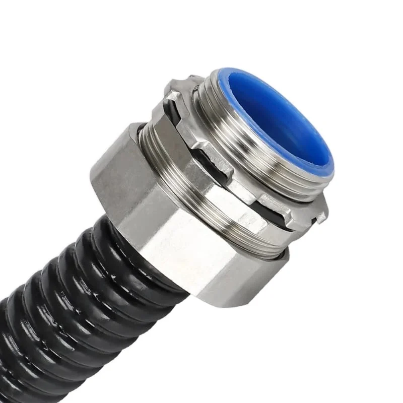
First identify whether the fitting grips a bare metal spiral, a metallic core beneath a jacket, the jacket itself or a combination defined by the manufacturer. Do not assume a compression ring intended for a smooth cable jacket can retain an interlocked metal spiral. Likewise, a fitting that grips bare flexible metal conduit may have no sealing interface for a liquidtight outer jacket.
Follow the specified cutting and preparation method for flexible conduit. An unsuitable tool can unwind or distort it and leave a sharp edge. Jacketed products may need a controlled trim with a defined core length left exposed. I keep every supplied ferrule, liner, sealing sleeve, grounding component and washer. Use the drawing for their order and orientation.
Insert the conduit to the stated stop without twisting the spiral out of shape. Hold the fitting body and tighten the intended nut or screws in the specified sequence. Verify the observable end condition, such as insertion depth, gap, witness position or torque, given for that exact fitting. Extra compression can damage the jacket, restrict movement or distort the core without improving the entry seal.
The flexible section begins outside the connector, not inside its grip zone. Route the first bend far enough from the fitting to satisfy the conduit instruction, the conductors or cable inside, and the motion profile. Add a support or strain-relief feature when the connector would otherwise carry conduit weight, repeated flexing or a side load.
For moving equipment, I describe the motion rather than calling it “flexible duty.” Record bend direction, minimum and maximum positions and the cycle profile. Add torsion, speed, acceleration, temperature and nearby abrasion points. A connector suited to a fixed offset is not automatically qualified for continuous robotic motion.
Use a purpose-built fitting for flexible-to-rigid transitions
A transition between flexible conduit and rigid tube has two different termination interfaces. Use a fitting whose documentation names both sides, or use an engineered adaptor chain in which every joint has a controlled mechanical, sealing and electrical function.
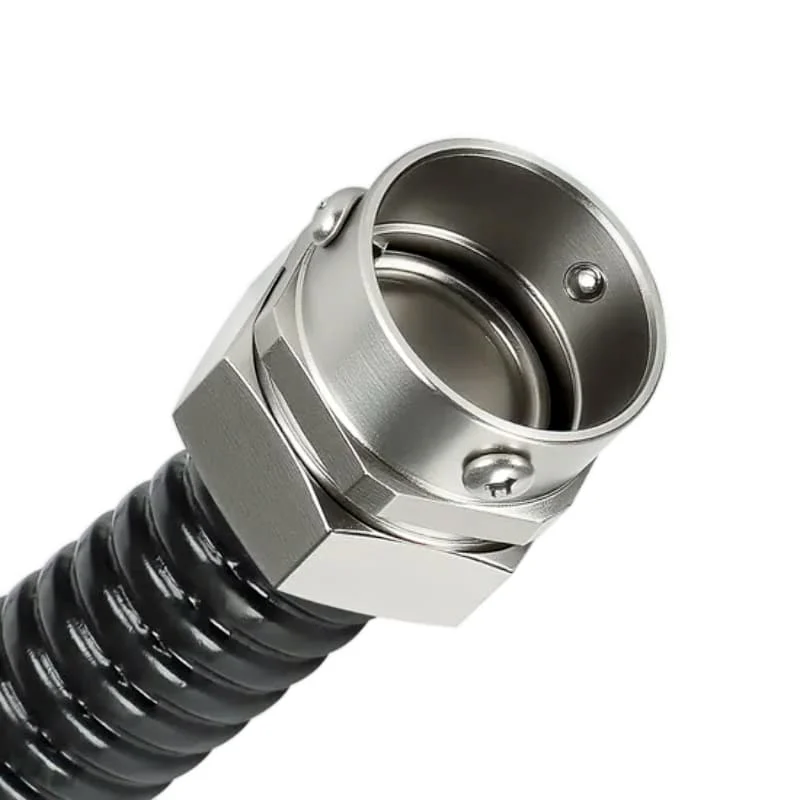
I use an adaptor only when each added interface has a documented function. A cable gland, loose reducer and conduit connector do not become a suitable assembly merely because their threads start. Each joint adds space and possible leak, loosening or bonding paths.
Check both thread forms and usable engagement, the seating seal and the intended conductive contact. The added joint also needs wrench access and appropriate certification coverage for the adaptor and adjacent parts.
Support both conduit runs so the transition does not become a structural hinge. The rigid side should arrive aligned; the flexible side should approach within its permitted bend and torsion. Provide enough access to hold the fitting body while each side is tightened independently.
Plan the flexible route and the cable inside it
The conduit bend and the enclosed cable bend are separate constraints. The tighter requirement controls the route. A large flexible-conduit radius does not prove that a shielded data cable, fibre cable or multi-core power cable inside is within its minimum bend limit.
Reserve the swept envelope, meaning all the space occupied throughout equipment movement. I check guards, doors, hot surfaces, edges and pinch points across that range. The conduit must also reach its maintenance position without pulling the connector or exceeding the enclosed cable’s bend limit.
At the physical route, locate the connector grip, first bend and independent support before accepting the layout. Walk the full swept envelope at the intended equipment positions.

Confirm from the actual conduit model, drawing and fitting instruction whether the black jacket covers a metal core and whether the connector is intended for that construction and size. Use the conduit and cable instructions to verify both bend limits and the permitted movement. Check connector retention, sealing and the complete installed arrangement by the specified methods; the routed shape alone supplies no acceptance result.
I also check how conductors will be pulled through the finished route. Confirm conduit fill—the space occupied by the wires—pulling method and tension, protection at the opening and permitted lubricant under the wiring design. A secure connector can still create a sharp pull angle or inaccessible draw path. Resolve these before fixing the last rigid support or flexible-service position.
Use the cable manufacturer’s static and dynamic bend factors for the actual cable. The preliminary route can be checked with the registered tool, then confirmed in the mechanical model and work instruction.
Check the bend-radius and entry-seal relationship before approving a side-loaded route. For conduit, add the connector’s own no-bend or straight-length requirement if the manufacturer states one.
Separate retention, sealing, bonding and EMC functions
Retention, sealing, protective bonding and EMC follow different physical paths through the fitting. Check each required function rather than treating one successful test as proof of them all.
| Function | Physical path | Evidence or installed check |
|---|---|---|
| Conduit retention | Conduit wall, spiral or jacket → grip/ferrule → fitting body | Correct product pairing, insertion and specified pull/rotation acceptance |
| Conduit-end sealing | Jacket or conduit surface → sealing element → fitting body | Represented conduit dimensions, surface condition and assembly end point |
| Enclosure-entry sealing | Fitting shoulder or thread → entry seal → panel/hub | Hole or thread compatibility, sealing land, seating and represented ingress test |
| Protective bonding | Metal conduit → connector contacts → body → enclosure/protective conductor | Defined safety path, suitable joints and project continuity result |
| EMC continuity | Conduit or screen → controlled circumferential contacts → chassis | Frequency-dependent system requirement and represented EMC measurement |
Ingress protection is an enclosure result. An IEC 60529 IP code classifies the degree of protection provided by the enclosure under its represented conditions. Specify the exposure and obtain evidence for the conduit, fitting, entry seal, enclosure wall or hub, installation condition and test. Check the enclosure-entry sealing path separately from the conduit-side seal.
Do not use an IP code as a corrosion, pressure, chemical or fatigue rating. A liquidtight conduit construction also does not make every cut end or transition liquidtight. Identify the lowest represented interface in the assembled route and test the enclosure configuration required by the project.
Verify protective bonding and EMC as different electrical tasks
Protective bonding is the intentional electrical connection of conductive parts into the protective path defined by the electrical design. If metal conduit participates in that path, the design must state how continuity crosses every coupling, connector, coating and enclosure joint. For IEC-based installations, IEC 60364-5-54:2011+A1:2021 is the reference for earthing arrangements, protective conductors and protective bonding conductors. Apply the edition and installation rules adopted for the project and jurisdiction.
Do not scrape paint, plating or protective finishes by default. Use bonding hardware, contact preparation and corrosion protection defined by the enclosure, fitting and electrical design. A star washer or locknut is not universal evidence of a qualified fault-current path.
IEC 61557-4:2019 covers equipment for resistance measurements on earth, protective-earth and equipotential-bonding conductors. Equipotential bonding connects conductive parts to limit differences in electrical potential. I specify the test current, connection points, compensation method, acceptance limit and record format for the project.
NIST’s metrological-traceability policy links a measurement result to a reference through its documented calibration chain. Instrument identity alone does not establish that link. There is no universal 25-ohm limit for every conduit-to-enclosure joint.
A passing low-frequency continuity check does not establish high-frequency shielding. Joint geometry, contact circumference, surface condition, conductor length and frequency affect EMC behaviour. IEC 61000-5-7:2001 gives enclosure-shielding methods and classifications within a defined test boundary.
I require the EMC claim to state frequency range and complete assembly, rather than relying on a continuity buzzer. Use the transfer-impedance test method for a quantified high-frequency path. It relates current on one side of the shield path to resulting voltage on the other under the stated method.
Install the rigid or flexible assembly in a controlled sequence
Make the equipment safe before opening the conduit route. Confirm that the conduit, fitting, enclosure and accessories form the specified arrangement, then follow the fitting instructions and electrical design requirements.
Rigid-conduit sequence
- Verify conduit type, size, thread or plain-end condition and fitting identity.
- Cut or thread the end with the specified tooling; deburr and clean it without reducing the required wall or finish.
- Align and support the conduit independently of the enclosure fitting.
- Assemble the connector, bushing, face seal, washer, locknut or hub components in the documented order.
- Start threads by hand and hold the stated body feature while tightening.
- Confirm seating, usable engagement, throat protection and conductor-pulling clearance.
- Complete support, sealing and electrical tests before energization.
Flexible-conduit sequence
- Verify bare or jacketed construction, size, OD range, spiral profile and connector identity.
- Cut square with the specified method and prepare the jacket or core to the stated dimensions.
- Fit the ferrule, liner, grip and seals in the documented orientation.
- Insert the conduit to its stop without unraveling, crushing or twisting the core.
- Tighten the designed nut or screws while holding the body and observing the stated end condition.
- Set the first bend, support and motion envelope outside the connector grip zone.
- Inspect jacket compression, exposed core, sharp edges, conductor clearance and enclosure seating.
- Complete retention, ingress, protective-bonding and EMC checks required for the project.
Do not hide a failed interface by adding tape, sealant, threadlocker or extra torque unless the product instruction specifically permits that material and method. Preserve the as-found condition, identify which path failed and correct the part selection or preparation.
Conclusion: Treat every conduit-entry function separately
Using a gland with rigid or flexible metal conduit succeeds when the selected component is a documented conduit fitting for the exact end construction. Rigid conduit needs thread or plain-end compatibility plus alignment and support. Flexible conduit needs the correct spiral or jacket grip, controlled preparation and a bend or motion plan outside the connector.
Check conduit retention, conduit-side sealing, enclosure-entry sealing and protective bonding independently. Where EMC matters, use a frequency-based assembly check as well. A secure grip alone does not establish a watertight enclosure or an electrical path; the selected conduit, fitting, support and mounting must provide each required function.
FAQs about glands for metal conduits
Can an ordinary cable gland clamp flexible metal conduit?
Only when the manufacturer’s documentation explicitly identifies that gland or fitting for the exact flexible conduit construction and size. A cable-seal range for a smooth jacket does not establish retention on a metal spiral or compatibility with a liquidtight conduit core.
Can the same fitting be used for rigid and flexible metal conduit?
Use one fitting for both only when its drawing, instructions and applicable certification name both conduit types and sizes. Rigid threads, plain tube walls, bare spirals and jacketed flexible conduit need different gripping and preparation features.
Does metal conduit automatically provide protective grounding?
No. The electrical design must define whether the conduit participates in the protective path and how continuity crosses every connector, adaptor, coating and enclosure joint. Test the installed path with the specified method and project acceptance limit.
Do conduit threads alone make the enclosure entry watertight?
No. Identify the documented sealing surface: thread, face seal, gasket, hub or another feature. Also verify the conduit-side seal. The enclosure IP result applies only to the represented complete arrangement and test condition.
How close can flexible conduit bend to its connector?
Follow the flexible-conduit and connector manufacturers’ stated straight-length, bend-radius and movement limits, then check the cable inside. Place the first bend and support so side load and repeated motion do not act inside the connector grip zone.
Sources and technical references
- IEC 61386-1:2008+A1:2017, Conduit systems for cable management - General requirements, accessed 2026-09-13.
- IEC 61386-21:2021, Particular requirements for rigid conduit systems, accessed 2026-09-13.
- IEC 61386-23:2021, Particular requirements for flexible conduit systems, accessed 2026-09-13.
- IEC 60423:2007, Outside diameters and threads for conduits and fittings, accessed 2026-09-13.
- IEC 62444:2010, Cable glands for electrical installations, accessed 2026-09-13.
- IEC 60529, Degrees of protection provided by enclosures, accessed 2026-09-13.
- IEC 60364-5-54:2011+A1:2021, Earthing arrangements and protective conductors, accessed 2026-09-13.
- IEC 61557-4:2019, Equipment for measuring resistance of earth and equipotential-bonding connections, accessed 2026-09-13.
- IEC 61000-5-7:2001, Enclosure shielding installation and mitigation guidelines, accessed 2026-09-13.
- UL 514B, Conduit, Tubing, and Cable Fittings, accessed 2026-09-13.
- NIST, Metrological Traceability: Frequently Asked Questions and Policy, accessed 2026-09-13.