

A chemical resistance chart helps you shortlist vent-plug materials only when its exposure conditions resemble yours. The housing, porous membrane, mounting seal and their joints can respond differently to the same chemical. Temperature, concentration, contact time and mechanical stress can change the result. A sound housing cannot compensate for a membrane that loses airflow or a seal that swells. Compare each material under the relevant exposure, then check whether the complete vent still passes air and resists the liquid it must keep out.
Key takeaways
- A rating such as Good or Excellent is useful only when the chart defines what was tested and under which conditions.
- Housing, membrane, seal and joining materials may have different chemical limits.
- Match chemical identity, concentration, temperature, contact mode and duration to your application.
- An unchanged appearance does not prove retained airflow, liquid resistance or attachment.
- The assembled vent needs to retain the functions your enclosure depends on.
How to read a vent-plug chemical resistance chart
A useful chart lets you find the evidence behind each rating. I would look for five things in every cell: tested material, exposure, measured property, acceptance limit and source. If these do not match the intended use, mark the result Conditional or Unknown rather than assume it passes.
A broad name such as PTFE, nylon, polyethylene, brass or stainless steel leaves important details open. Grade, filler, temper, finish, porosity, processing and geometry can all matter. Also ask what “no visible change” actually tells you. A housing can look unchanged while its thread strength or dimensions fall outside the required limit. A membrane may remain in place while its pressure-flow curve, wetting or attachment changes. The chart should show these gaps clearly.
The same chart result can have different implications for different parts. Housing distortion may affect the thread, membrane damage may affect airflow, and a weakened bond may allow liquid around the membrane. Read the material rating together with the property measured and the function that property supports.
If a chart gives only a material name and a rating, you cannot tell whether it covers your exposure. Look for the tested grade, chemical, temperature, contact time and measured change before using it to select a vent.
Use four project-defined outcomes:
| Outcome. | Meaning for one chart row. | Allowed next step. |
|---|---|---|
| Supported. | Exact material or part, exposure conditions, measured property, and acceptance limit match the intended use closely enough for that decision. | Carry the result into complete-vent verification. |
| Conditional. | Evidence is relevant, but one or more conditions, properties, or interfaces are not represented. | Name the gap and add bounded evidence before acceptance. |
| Reject. | The candidate failed a defined property or functional limit under the represented condition. | Remove it from that duty unless the design or exposure changes. |
| Unknown. | Identity, method, condition, property, or result is missing or too dissimilar. | Do not infer compatibility from the material family. |
These are decision labels for the project, not universal definitions supplied by ASTM or IEC. State the rule beside the chart. Never assume another supplier’s Excellent or Good category uses the same exposure time, property limit, or rating logic.
A supplier’s Good or Excellent may refer to a short exposure, a particular concentration or appearance alone. Check that definition before assuming the vent will withstand your process chemical.
A short material test can help eliminate unsuitable candidates. It does not by itself show how long the complete vent will last or whether its airflow and sealing survive repeated use.
Split the vent into independent compatibility rows
A vent plug contains several exposed materials and joints, each with a different job. Besides the polymer or metal housing, the gas path may include a porous membrane, backing or support, attachment zone and cap. The installed vent also has a mounting seal, thread treatment and enclosure surface. Liquid, mist, vapor, condensate and cleaning residue may reach them by different routes.
I would draw those contact routes before building the chart. Give each layer that can change a required function its own row. The chemical-resistant cable gland guide uses the same component approach for glands. A vent adds another check: does the gas path still work after exposure? A sound body cannot compensate for a blocked membrane, and a sound membrane cannot compensate for an attacked washer or bond.
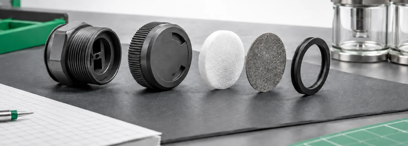
| Vent layer. | Identity that belongs in the chart. | Property changes worth screening. | Finished function to repeat. |
|---|---|---|---|
| Housing and cap. | Exact resin grade and additives, or exact alloy, finish, and manufacturing state. | Dimensions, cracking, strength, mass or surface loss, thread condition, and distortion. | Mounting, mechanical integrity, and unobstructed internal passages. |
| Porous membrane. | Exact polymer, construction, support, thickness, active area, processing, and attachment. | Mass or dimensions where meaningful, pore response, wetting, damage, and attachment. | Bidirectional pressure-flow behavior and the specified liquid or barrier test. |
| Mounting seal. | Exact elastomer compound, cure, hardness, geometry, compression, and lubricant. | Volume, mass, dimensions, hardness, tensile behavior, cracking, and recovery. | Sealing at the installed interface under the represented state. |
| Support or joining interface. | Adhesive, weld, insert, backing, crimp, overmold, or other exact construction. | Adhesion, movement, cracking, voids, extraction, and loss of support. | Membrane retention, edge sealing, and resistance to bypass leakage. |
| Mating enclosure surface. | Exact substrate, coating, hole, thread, washer stack, and installation condition. | Coating attack, crevice condition, dimensional change, and surface damage. | Complete mounted-boundary performance. |
Describe the chemical duty before assigning a rating
Compare the chart with the conditions at the vent: chemical formulation and concentration, temperature, contact mode and duration. Repeated mist, condensate, cleaning residue and wet/dry cycles can differ substantially from continuous immersion. Pressure, mechanical stress and the sequence of fluids also affect whether a result applies.
IEC 60068-2-74:1999+A1:2018 gives a standardized method for accidental contact with representative fluids. It explicitly excludes continuous contact. So a short wipe or splash result cannot stand in for immersion. An immersion result can also miss a stressed thread, thin bond line, one-sided membrane exposure or cleaning sequence. If a missing condition could change the failure mechanism, mark the row Conditional or Unknown and name the gap.
These details help you judge whether a chart entry applies:
- Chemical: formulation, concentration, carrier and contaminants.
- Contact: immersion, splash, wipe, spray, vapor, condensate or residue, including repeated wet/dry cycles.
- Conditions: temperature, pressure difference and mechanical stress.
- Material: the actual grade, compound, finish or membrane construction.
- Measured change: for example dimensions, strength, corrosion, airflow or seal behavior.
- Meaning of the rating: the property limit used, including any recovery period after exposure.
Do not average separate exposures into an imaginary middle condition. If an alkaline wash is followed by a water rinse and an acidic process splash, record the sequence. Swelling during one stage and shrinkage during the next can matter even when a single endpoint looks close to its starting dimension.
Writing the wet, rinse, dry, and re-exposure order in plain language can reveal a missing contact state before any specimen is prepared.
Interpret polymer and metal housing evidence separately
Use different property columns for polymer and metal housings. Their damage mechanisms differ. ASTM D543-21 evaluates plastics under stated reagents, concentration, temperature, contact duration or stress. It reports changes such as weight, dimensions, appearance, color, strength and other mechanical properties. Its published guidance mainly uses short tests to eliminate unsuitable materials or suggest a probable relative order when end-use conditions differ.
For a molded vent housing, I would compare the tested resin grade, fillers, color package, molding state, applied stress and relevant geometry with your part. A mass result alone cannot clear cracking at a stressed thread root, cap distortion, insert movement or a change in the internal passage shape.
ASTM G31-21(2025) guides laboratory immersion corrosion testing of metals. It asks for records of solution composition, temperature, gas sparging, fluid motion, specimen support, duration, cleaning and other factors. Gas sparging means introducing gas into the test solution. The guide also warns that accelerated tests may be only indicative or misleading.
For a metal housing, record the alloy, temper, finish, passivation or plating, surface condition and crevices. Include contact with other metals and stressed features. I would ask which damage mode the result covers. General mass loss may not answer questions about pitting, crevice attack, environmentally assisted cracking, coating damage or galvanic behavior. Keep those results separate rather than convert them into one broad resistance grade.
For a broader comparison of cable-gland bodies and seals, use the component-level chemical resistance guide. Keep this vent chart focused on the housing’s ability to support the porous path and mounting interface after exposure.
Treat membrane survival and vent function as separate columns
For a porous membrane, check material condition and vent performance separately. The material name does not establish stable pores, usable area, attachment, dry or wet flow, or resistance to liquid entry. Record the membrane grade or laminate, thickness, support, processing, active area, bond perimeter, orientation and preconditioning. Then compare the same measurements before and after the stated chemical exposure.
I would keep the evidence levels in the ePTFE gas-permeability guide separate: specimen permeability, membrane permeance, finished-vent pressure-flow data and installed enclosure response. Unchanged sample mass cannot show that a capped and bonded vent equalizes pressure. Likewise, retained airflow at one point does not prove resistance to the specified liquid.
ASTM F316-03(2019) covers bubble-point and mean-flow-pore tests for membrane filters. Its public scope says bubble point can indicate membrane damage, ineffective seals or a system leak. It does not establish particle retention on its own. When the membrane and wetting liquid suit the method, comparing results before and after exposure can help reveal a pore or integrity change. It is not a chemical resistance ranking.
Chemical exposure can also change wetting. Keep the test liquid, conditioning, fixture and interpretation the same for a valid comparison. Then separately repeat the finished vent’s pressure-flow measurement in both directions and its specified liquid or barrier test. The hydrophobic and oleophobic vent comparison explains why a clean-water result cannot be carried over to oils, surfactants or other low-surface-tension contaminants.
Keep seals and joining interfaces visible in the chart
Give the mounting seal and membrane attachment their own outcomes. They often use materials different from the housing and membrane. ASTM D471-16a(2021) compares the effect of liquids on rubber and rubber-like compounds. Its outputs include changes in mass, volume, dimensions, hardness, tensile strength and elongation. It also notes that accelerated exposure may not correlate directly with actual part performance because service conditions vary.
For a washer or O-ring, I would record the compound and cure, installed compression, liquid contact, temperature, time and recovery state. Connect each property limit to the seal’s job. Swelling can change compression; shrinkage can reduce contact. Hardness or tensile changes can affect how the part behaves during assembly. EPDM, silicone, NBR and FKM are family names. They cannot replace data for the specific compound.
Treat membrane bonds, welds, crimps, inserts, supports, and overmolded interfaces the same way. A chemical can leave both bulk materials intact while weakening adhesion or creating a bypass path at their edge. Use the actual joint geometry and stress state in the chosen evaluation. After conditioning, check attachment and bypass leakage as separate outcomes. The sterilizable vent-plug material guide shows why a process-compatible material family still cannot qualify every support, seal, and joining layer in an assembled vent.
Resolve incomplete chart entries without guessing
If the chart conditions differ from your application, mark the row down and explain the mismatch. I would first ask whether you are only screening candidates or making an acceptance decision that depends on the result. That determines how closely the next evidence needs to match. Do not interpolate across chemicals, concentrations, temperatures, grades or contact modes without a validated relationship. Moving up one undefined rating is not a usable safety margin.
For example, a chart may report no visible change in a named housing resin after room-temperature immersion in one solvent. Your vent will face heated solvent vapor, repeated cooling condensate and stress in its molded threads. It also contains an elastomer washer and an adhesively bonded membrane. I would mark the housing Conditional: temperature, contact mode, stress and useful property measurements do not match. The untested membrane, seal and bond are Unknown. One favorable cell cannot make the complete vent Supported.
A useful next test could expose the molded housing and joined vent to the actual sequence. Then measure dimensions, thread condition, attachment, pressure-flow response in both directions, bypass leakage and required liquid resistance. The chart’s job is to show this missing work plainly.
A material result and an assembled-vent result answer different questions:
- A material chart can eliminate a candidate that is clearly incompatible with the chemical.
- Testing the specific compound or joint helps address the property that could fail.
- Testing the assembled vent includes the cap, support, bond, seals and passages that a coupon omits.
- Exposure sequences and recovery conditions help represent the duty the enclosure will actually face.
Stop at the evidence level needed for the decision. A benign external cleaning wipe may not justify a full lifetime program, while continuous aggressive contact or a safety-relevant barrier can require more representative testing and application-specific review.
A focused question is often more useful than a broad test program: will the heated chemical weaken this bond, swell this washer or reduce airflow through this membrane?
Check whether the complete vent remains suitable
A suitable vent needs more than one favorable housing result. A weak bond, incompatible washer or damaged membrane can defeat the whole assembly. Where a chart leaves a function-critical material untested, ask for data that covers that gap before relying on the vent in that exposure.
Then repeat the applicable pressure-flow, liquid or barrier, attachment and mounting checks for the selected vent and enclosure. A material chart does not establish an IP code, universal chemical rating, maintenance interval or service life. The NIST Service Life Prediction of Filled Polymers project explains that qualification tests may detect early failures without predicting long-term reliability. They may also omit environmental stresses acting together.
If the assembly, supplier, compound, finish, membrane process, joint or exposure changes in a way that affects the evidence, reassess those rows. Do not automatically carry the previous assembly result forward.
Conclusion
For your vent plug, compare the chart conditions with the actual chemical exposure and consider the job of each layer. A housing needs to keep its shape and mounting strength; a membrane needs to retain its gas path and liquid resistance; seals and joints need to remain attached and tight. Missing conditions mean the chart cannot yet answer that part of the selection.
The chart should help you reject unsuitable candidates and decide what to check next. I would complete selection only when each layer that controls a required function is supported. After the stated exposure, the assembled vent must retain the required pressure-flow, liquid or barrier, attachment and mounting performance.
FAQs about vent plug chemical resistance charts
Is ePTFE chemically resistant to every fluid?
No. ePTFE identifies a material family, not the exact membrane construction or complete vent. Grade, processing, pore structure, support, joining, chemical formulation, temperature, wetting, stress, and exposure history matter. Even when bulk PTFE evidence is favorable, repeat the relevant membrane and finished-vent functions after representative exposure.
Does a supported housing row mean the vent plug is compatible?
No. The membrane, mounting seal, support, bond or weld, thread treatment, and mating enclosure surface may use different materials and see different contact. The assembled vent remains open until every function-critical layer has adequate evidence and the required post-exposure functions pass.
Can chart values be transferred to a higher temperature or concentration?
Not automatically. Temperature and concentration can change reaction rate, diffusion, swelling, corrosion mode, wetting, and mechanical response. Mark the result Conditional or Unknown unless the source covers the intended conditions or a validated relationship supports the transfer. Do not interpolate from an undefined Excellent or Good label.
Does an ingress rating prove resistance to process chemicals?
No. An ingress result belongs to its test medium, pressure, duration, orientation, assembly, and acceptance criteria. It does not establish compatibility with solvents, acids, alkalis, oxidizers, oils, surfactants, vapors, or cleaning residues. Chemical exposure and post-exposure vent functions need their own evidence.
What should I do when a chart says no effect but gives no method?
Treat the cell as Unknown for a load-bearing decision. Ask for the exact material identity, reagent formulation and concentration, temperature, contact mode, duration, stress, measured property, control, recovery state, acceptance limit, and result. Without those fields, “no effect” is not a transferable engineering conclusion.
Sources and technical references
- ASTM D543-21, Standard Practices for Evaluating the Resistance of Plastics to Chemical Reagents, accessed 2026-09-06.
- IEC 60068-2-74:1999+A1:2018, Environmental testing: Test Xc, Fluid contamination, accessed 2026-09-06.
- ASTM G31-21(2025), Standard Guide for Laboratory Immersion Corrosion Testing of Metals, accessed 2026-09-06.
- ASTM F316-03(2019), Standard Test Methods for Pore Size Characteristics of Membrane Filters, accessed 2026-09-06.
- ASTM D471-16a(2021), Standard Test Method for Rubber Property: Effect of Liquids, accessed 2026-09-06.
- NIST, Service Life Prediction of Filled Polymers Project, accessed 2026-09-06.