

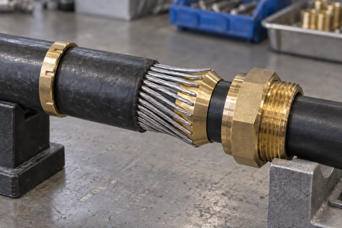
The armor cone in an SWA cable gland supports the prepared steel wires while its matching clamp captures them around the intended contact band. SWA means steel wire armoured. I would select the cone and clamp as parts of the identified gland kit. Jacket sealing, enclosure sealing, restraint against short-circuit forces, and electrical bonding still need their own interfaces and checks.
Key takeaways
- Select the cone and mating clamp as parts of one identified gland kit; similar-looking loose components are not interchangeable.
- Match the declared armour range as well as the outer-sheath and bedding diameters. Nominal conductor size cannot settle the fit.
- Spread the retained SWA wires evenly over the intended cone contact band and keep them out of seals and threads.
- Use the exact preparation dimensions, component orientation, closure condition, and torque stated for the gland size and cable construction.
- Inspect armour capture, cable sealing, entry sealing, cable support, and the designed electrical path as separate functions.
What is the armor cone in an SWA cable gland?
An armor cone is the shaped support beneath the retained wires in a cone-and-clamp SWA termination. “Armour cone” is the alternative spelling. The wires sit around its contact band, and a matching ring, sleeve, or body closes over them. This transfers armour load into the gland and may form part of an electrical path where the design provides that duty.
I would use the cone specified for the gland. Its angle, diameter, length, surface, direction, and mating part belong to that construction and armour range. Some designs use separate cones and rings; others use reversible parts or a different geometry. Check markings and the assembly drawing before deciding which arrangement applies.
BS 6121-1:2005 gives performance requirements and test methods for armour glands. IEC 62444:2010 addresses complete glands as supplied. I would purchase and assess the gland assembly within those scopes. A loose cone does not independently prove retention, sealing, or electrical performance.
Assign each gland function to the correct interface
Armour capture is the mechanical engagement of retained SWA wires between the specified cone and clamp. The cone supports and positions the wire ring; the mating part closes around it. A complete gland may also grip cable, provide seals, and carry an electrical path. I keep those duties separate so each part and inspection has a clear purpose.
| Function | Primary interface | What the cone contributes | Companion check |
|---|---|---|---|
| Armour capture | Retained SWA wires between cone and mating clamp | Supports and positions the wire ring in the intended contact band | Correct clamp part, orientation, closure, wire distribution, and armour range |
| Cable retention | Declared cable-gripping interface in the complete gland | May contribute indirectly through the armour termination | Complete gland retention rating, cable layer in the grip zone, and cable support |
| Conductive armour termination | Armour-to-clamp-to-body route, where the design provides it | Provides one metallic contact interface | Gland design, accessories, enclosure path, protective conductor design, and test result |
| Outer-jacket sealing | Elastomer acting on the cable sheath | The cone stays clear of this interface | Sheath diameter, roundness, surface condition, seal range, and specified compression |
| Enclosure-entry sealing | Face washer, O-ring, thread seal, or qualified entry joint | The cone stays inside the armour-clamp stack | Entry geometry, panel or boss, accessories, engagement, and sealing face |
| Short-circuit restraint | Cable cleats and their supports | The cone terminates armour at the entry | Cleat type, spacing, mounting, cable formation, and declared electromechanical performance |
Check two common failure points separately.
Visible contact between steel wires and a metal cone does not establish a protective-earth or fault-current rating for the installed route. A firm armour clamp cannot establish an enclosure IP degree. Use the armour earthing and bonding checks and entry-thread sealing checks for those interfaces.
Read the complete armour-clamp stack
An armour-clamp stack is the ordered cable layers, cone, clamp, and adjoining gland parts that terminate armour. It works only with correct preparation and component positions. I read the assembly from cable toward enclosure, using the following interfaces rather than treating every metal piece as interchangeable gland hardware.
- The outer sheath reaches the environmental seal on a clean, round, undamaged section.
- The cut edge of the outer sheath stops at the preparation point shown in the gland instructions.
- The retained SWA wires extend far enough to cover the cone contact band without entering a seal or thread.
- The bedding or inner sheath remains intact beneath the cone and reaches any inner seal specified by the design.
- The cone sits in the stated direction and location; a reversible part is set to the marked orientation for the identified armour construction.
- The mating ring, sleeve, or body closes around the full wire circumference as designed.
- The gland body, entry seal, locknut, earth accessory, and enclosure interface remain correctly ordered and separately inspectable.
I would use the current instructions for the identified gland and cable. Designs can have different strip lengths, component directions, wire-forming methods, closure criteria, and intermediate inspection steps. A borrowed sequence may leave wire ends outside the contact band or push them into a seal.
Match the cable, cone, and clamp before purchase
Cone selection starts with cable construction and layer dimensions. An M25 or M32 entry thread does not state armour wire size, diameter over bedding, outer-sheath diameter, or clamp range. Bedding is the layer beneath the armour. I would check each cable layer the gland seals, grips, or clamps.
For example, a cable may fit the outer-seal range while its armour dimensions fall outside the cone-and-clamp range. That is still a mismatch. The entry thread may fit the enclosure. Select a gland whose published ranges cover every cable layer used for sealing, retention, and armour capture.
IEC 60502-1:2021 addresses construction, dimensions, and tests for specified power-cable voltage classes. I start with the maker’s data for the complete cable designation. Take field measurements wherever gland instructions require, at the intended sealing and clamping positions. An oval, aged, ribbed, or repaired cable may need particular attention to its actual condition.
I would send the supplier or designer the following fixed inputs. EMC means electromagnetic compatibility; AC means alternating current. These electrical duties need to be identified alongside the physical cable:
- cable manufacturer, full designation, rated voltage, core count, and conductor size;
- armour material and construction, individual wire dimension where required, and measured diameter over armour;
- measured diameter over bedding or inner sheath and measured outer-sheath diameter;
- required gland type, entry thread and length, panel thickness or threaded-boss details, and available installation space;
- indoor, outdoor, corrosive, immersed, washdown, vibration, temperature, or hazardous-location conditions;
- retention, ingress, fire, electrical bonding, EMC, certification, and accessory requirements;
- cable formation, support or cleat plan, and any single-core AC constraints from the electrical design.
For a broader cable-versus-gland decision, compare the armoured and unarmoured gland functions. When a schedule offers single- and double-compression constructions, use the compression-gland comparison to identify which cable layers each design seals; neither label removes the need to verify the cone and armour range.

Keep the identified cone and mating clamp with their gland kit, then compare the prepared cable layers with the declared armour and seal ranges before assembly.
Prepare the SWA so the cone can work
Good cone contact begins with the preparation marks. I would obtain the cable drawing and current gland instructions before stripping. Set a datum, a consistent measurement starting point, and mark sheath cutback and armour length separately. Stage parts in their documented order. A borrowed strip length can leave wires short of the contact band or inside a seal.
Preparation also requires the site’s safe system of work. The HSE’s Electricity at work: safe working practices is one official reference for electrical-equipment work. Follow the governing law, competence rules, isolation and stored-energy controls, proving-dead procedure, personal protective equipment (PPE), and authorization requirements.
Remove the sheath with a controlled cut that does not nick armour. Cut away the unwanted wires without damaging bedding, clear fragments, and inspect the circumference. Stop for partly cut or missing wires, deep nicks, excessive corrosion, or sharp kinks. Tape cannot restore wire condition or change the gland’s range.
Form the retained wires by the permitted method and distribute them evenly around the cone. Do not braid, double, pack, or selectively trim them to make the clamp close. Keep cut ends in the intended region and clear of seal seating surfaces and threads. For a reversible cone or ring, check the marking before seating the cable.
BS 6121-5:2005 gives recommendations for selection, installation, and inspection of cable and armour glands in its stated scope. Its public scope also excludes explosive atmospheres, so a BS 6121 installation routine cannot replace the certified instructions and hazardous-location rules where Ex equipment is involved.
Close the armour clamp without hiding a mismatch
Correct closure brings the specified parts together with the cable axial and wires evenly seated. Start threads by hand and counter-hold the adjoining body, holding it against rotation. Tightening must not twist the cable, drag wires around the cone, or disturb the enclosure joint. Follow the specified torque, turns, metal-to-metal position, inspection step, or other closure criterion.
I would not transfer torque from a similar gland. Friction, plating, thread form, seal load, cone geometry, part condition, and permitted assembly aids may differ. If the instructions require reopening once to inspect armour bite, follow that sequence. Otherwise leave the completed clamp closed unless another action is specified.
Unexpected resistance is a stop signal.
Stop when the joint cross-threads, a nut bottoms before the armour is captured, the bedding moves through the cone, wires bunch on one side, or a component leaves too little thread engagement. Compare the complete kit with its parts drawing and recheck the cable measurements. Extra force cannot correct an out-of-range cone, wrong orientation, mixed gland size, or incorrect cutback.
Keep electrical bonding separate from mechanical capture
A captured armour ring can be one link in an electrical route, but the route must be designed and tested as a whole. IEC 60364-5-54:2011+A1:2021 addresses earthing arrangements, protective conductors, and protective bonding conductors. Apply the governing installation rules and project design to determine whether the armour, a separate protective conductor, an earth tag, the gland body, and the enclosure participate in the protective path.
Map the intended route before installation:
SWA armour → cone-and-clamp interface → gland body → entry interface or earth accessory → enclosure/protective conductor → earthing arrangement
I would inspect every possible break in that route: insulating coating, unsuitable washer, loose locknut, corroded contact, unapproved thread material, missing earth accessory, or an enclosure not intended to carry the required current. The electrical design and rules must set the test method and permissible result, fault duty, conductor arrangement, instrument, and acceptance criteria. There is no universal cone-resistance target.
The metal-gland grounding checklist helps trace the enclosure side of the route. If EMC is required, I would also verify the complete screen-termination strategy. High-frequency transfer impedance describes coupling through a screened path. It is a different performance question from low-frequency protective bonding.
Keep IP protection separate from the cone
The armour cone does not seal the jacket or enclosure entry. IEC 60529 classifies enclosure ingress protection (IP). The result depends on seals, contacted cable layers, entry face or thread, accessories, assembly, orientation, and test configuration.
I would check the outer seal on undamaged sheath within its range. Then inspect the enclosure joint. A threaded boss, the raised threaded entry feature, needs the correct thread and engagement. A clearance hole needs the specified hole, thickness, face seal, anti-rotation provision, and locknut. Extra back-nut torque cannot repair a missing seal, damaged coating, wrong thread, or tilted washer.
Apply the IEC 60529 selection criteria when defining the enclosure requirement. Do not improvise a spray, immersion, or pressure test on connected equipment; define a safe method and acceptance basis for the actual assembly in the site test procedure.
Let cable cleats carry cable-system forces
The gland terminates the entry; cable cleats and supports carry external loads. Cleats are clamps securing the cable route. IEC 61914:2021 covers them and intermediate restraints, including declared electromechanical-force resistance. Position the cable so weight, bending, vibration, thermal movement, and installation pull do not lever the cone and clamp.
I would select short-circuit restraint from the project calculation and declared system performance. Include cleats, spacing, cable formation, hardware, and support structure. The cable-cleat relationship separates those route duties from gland duties.
An unsupported vertical run, a tight bend immediately outside the enclosure, or a cleat arrangement that was not selected for the prospective fault can still overload a firm gland. Conversely, a qualified cleat system does not correct loose armour inside the gland. Check both systems before energization or return to service.
Diagnose cone and clamp problems by symptom
Cone faults leave visible contact patterns. Isolate the equipment and follow the site’s safe work controls before disturbing an installed termination. Open the gland only when the installation rules, environmental conditions, and hazardous-area controls permit that inspection method.
| Observation | Likely interface to examine | Required disposition |
|---|---|---|
| Armour is loose after the specified closure | Armour range, cone or ring orientation, component mix, preparation length | Stop; identify the mismatch and replace or re-prepare under the instructions. Do not add shims or spare wire. |
| Wires are bunched on one sector | Cable centering, wire forming, cable rotation during tightening | Re-prepare if permitted; restore a full, even wire ring before closure. |
| Individual wires escape the clamp | Cut length, contact-band position, damaged wire, clamp alignment | Reject the captured condition and inspect every retained wire. |
| Bedding is nicked or pinched | Armour cutting depth, cone position, cable size, trapped debris | Assess the cable under the cable maker’s and project rules; a gland cannot make hidden bedding damage acceptable. |
| Nut bottoms while armour remains free | Wrong size, missing or inverted component, out-of-range cable | Segregate the parts and compare markings and measurements with the kit drawing. |
| Continuity result is absent or unstable | Complete designed electrical route, including the cone contact | Trace every interface and accessory using the specified test method. |
| Water appears at the entry | Outer seal, cable surface, enclosure face or thread, orientation | Locate the actual ingress path; tightening the armour clamp is not a sealing repair. |
| Cable moves under service load | Cable support, gland retention interface, armour capture | Remove the load, inspect damage, and correct the support and entry system before return to service. |
Inspect the completed SWA entry
A completed SWA entry should match its cable-and-gland specification and pass each assigned check. I would record cable identity and measured layers, gland maker and part number, cone or ring setting, seals, accessories, and strip dimensions. Add closure values, controlled-torque tool identity, enclosure details, electrical method and result, supports, inspector, and date.
Outside the closed gland, check centring, sheath twist or extrusion, expected joint engagement, a flat entry seal, accessory order, and resistance to body rotation. If the instructions include armour inspection before closure, record the even capture then. Later inspections should check movement, loosening, corrosion, displaced seals, damage, and support changes.
For hazardous locations, IEC 60079-14:2024 adds requirements for design, selection, installation, documentation, personnel competency, and initial inspection of Ex electrical installations. IEC 60079-17:2023 addresses inspection and maintenance of electrical installations in explosive atmospheres; follow the certificate-linked instructions for the exact gland and preserve the installation record needed to inspect that configuration.
Never authorize a substitution in certified equipment from a generic SWA cone arrangement.
Conclusion
The armor cone supports the retained SWA wires; the matching clamp captures them. Reliable performance still depends on the complete, identified assembly. Match the cable’s armour and sealing dimensions to the gland range, keep the cone and mating clamp together, prepare every cable layer to the stated dimensions, distribute the retained wires evenly, and close the joint only to its documented condition.
Before energization or return to service, I would verify five outcomes separately: armour capture, retention and support, jacket sealing, entry sealing, and the designed electrical route. This makes fault finding clearer. Tightening the armour clamp cannot substitute for repairing a seal, bond, entry, or cable-restraint problem.
FAQs about armor cones in SWA cable glands
Can an SWA cable gland work without its armour cone?
Not when the identified gland design uses a cone as part of its armour-clamp stack. Omitting it changes the assembly and removes the intended support beneath the retained wires. Use every specified component in the stated order; if a part is missing or damaged, replace the kit or component only as the manufacturer’s instructions allow.
How do I know whether the cone fits my SWA cable?
Check the gland’s declared armour acceptance range and required cable dimensions against the actual cable construction and field measurements. Confirm armour material and wire dimension where specified, diameter over bedding, outer-sheath diameter, cone or ring orientation, and gland size. Entry thread size alone does not establish the fit.
Should all retained armour wires sit evenly on the cone?
Arrange the retained wire ring as shown in the gland instructions, with full circumferential distribution in the intended contact band. Missing, crossed, bunched, shortened, escaped, or partly cut wires require inspection of the entire prepared end and usually full re-preparation under the current gland instructions. Do not trim selected wires or add packing to make a doubtful clamp close.
Does the armour cone provide the cable’s earth connection?
It may form one conductive interface in a designed armour-termination route, but it does not prove the entire protective or functional electrical path. Confirm the gland design, earth accessories, enclosure interface, protective-conductor arrangement, governing rules, fault duty, and specified test result for the complete installation.
What torque should I apply to the armour-cone assembly?
Apply only the torque or other closure criterion stated for the exact gland, size, component, cable construction, and instruction revision. Never borrow torque from a similar thread. Counter-hold the adjoining body and stop if the joint bottoms, cross-threads, distorts parts, or leaves the armour loose.
Sources and technical references
- BS 6121-1:2005, Mechanical cable glands: armour-gland requirements and test methods, accessed 2026-09-13.
- IEC 62444:2010, Cable glands for electrical installations, accessed 2026-09-13.
- IEC 60502-1:2021, Power cables with extruded insulation and accessories, accessed 2026-09-13.
- BS 6121-5:2005, Selection, installation, and inspection of cable and armour glands, accessed 2026-09-13.
- HSE HSG85, Electricity at work: safe working practices, accessed 2026-09-13.
- IEC 60364-5-54:2011+A1:2021, Earthing arrangements and protective conductors, accessed 2026-09-13.
- IEC 60529 consolidated version, Degrees of protection provided by enclosures, accessed 2026-09-13.
- IEC 61914:2021, Cable cleats for electrical installations, accessed 2026-09-13.
- IEC 60079-14:2024, Explosive atmospheres installation design, selection, installation, and initial inspection, accessed 2026-09-13.
- IEC 60079-17:2023, Explosive atmospheres electrical installation inspection and maintenance, accessed 2026-09-13.