

An industrial cable gland combines a suitable body, a seal matched to the cable, secure retention and a sound enclosure connection. Its construction should keep those functions working under the installation’s temperature, fluids, cable loading and electrical requirements.
I start with the parts and their jobs: what carries the load, what seals each opening, and what connects the cable to the enclosure. That makes the choice between polymer, plated brass, stainless steel and specialised designs much clearer.
Key takeaways
- Choose the body material for the environment, structural duty and required electrical path.
- Match the seal compound and profile to the cable surface, diameter range and surrounding fluids.
- Trace cable forces through the grip, gland body and enclosure; provide external support for the cable route.
- Treat the cable seal and the enclosure-entry seal as separate interfaces.
- Add armour termination, screen contact or hazardous-area construction where the application needs it.
What makes an industrial cable gland suitable for the job?
“Industrial grade” is a broad description rather than a particular IEC classification. A useful specification turns that description into construction choices: body and seal materials, cable range, entry thread, retention, ingress protection and any special functions.
IEC 62444:2010 provides construction and performance requirements and tests for complete cable glands supplied by the manufacturer. It is a useful starting point for comparing the assembled product. The guide to cable-gland functions explains the basic components and applications.
I separate the required duties before selecting a material. An unarmoured instrument cable entering a sheltered box has different needs from an armoured cable on vibrating equipment exposed to cleaning fluids. Both need a sound entry, but the second case adds another mechanical interface and a more demanding exposure profile.
How do body materials change the design?
The body holds the working parts in position and connects them to the enclosure. Its threads, shoulders and wrench flats transmit installation forces; its material and surface finish meet the surrounding environment. I compare those features together, because changing the body material while retaining an unsuitable seal leaves the fluid problem unresolved.
Polymer: match the formulation to the exposure
A polymer body can provide an insulating construction where the entry does not need to carry a protective bonding or screen connection through that body. For outdoor or heated equipment, I look at the supplied polymer grade, its stabilisation and the complete gland’s operating conditions.
Formulation matters. NIST’s filled-polymer research examines how polymer structure, fillers and interacting stresses such as moisture, temperature, radiation and load affect performance. For a gland selection, the practical lesson is to assess the actual material formulation and exposure together; the colour or generic name “nylon” is only part of the description.
I also check that the wrench flats are accessible, the enclosure wall supports the connection and the cable has suitable support. These details help the assembled polymer gland work within its intended mechanical duty.
Plated brass: separate the body from the finish
In a nickel-plated brass design, brass forms the underlying body and nickel forms the surface finish. The threads and body geometry carry the connection loads, while exposed surfaces meet the environment. At a scratch or worn thread where the finish is breached, the exposed material can be brass.
That distinction guides inspection: examine the finish around tool contact, thread entry and sealing seats as well as the visible cap. I match the gland and its mating enclosure materials to the expected wetting and chemical exposure. The plated-brass and stainless comparison discusses those corrosion choices in more detail.
Stainless steel: select the grade for the medium
Stainless steel obtains corrosion resistance from its protective passive surface. Alloy choice changes that resistance: the British Stainless Steel Association explains how chromium, molybdenum and other alloying elements influence different forms of corrosion in its selection guidance.
I therefore specify a grade against the actual liquid, contamination and temperature, then check the seals and accessories against the same duty. A stainless body paired with an unsuitable washer still leaves a vulnerable entry. For threaded assembly, follow the selected product’s surface preparation and lubrication instructions; these affect tightening and the condition of the mating threads.
| Body construction | Feature to consider | Useful selection question |
|---|---|---|
| Polymer | Formulation, insulating construction, thread and body support | Does this grade and complete assembly suit the exposure and mechanical duty? |
| Nickel-plated brass | Brass body beneath a nickel finish | What reaches the surface, and where might assembly or service damage the finish? |
| Stainless steel | Grade-dependent corrosion behaviour | Does the alloy suit the medium, and do seals and accessories suit it too? |
| Any metal body used electrically | Defined conductive contacts to cable and enclosure | Where does the required bonding or screening path actually run? |
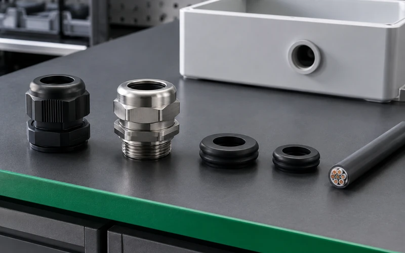
The material review separates the body, seal, cable surface, and enclosure entry so each interface can be matched to the actual exposure and assembly.
What makes the sealing system effective?
Seal compression is the deformation that brings the sealing element into contact with its mating surfaces. In a typical compression gland, closing the cap loads the insert so it conforms to the specified cable surface. The insert’s shape, support and material determine how that deformation develops.
Fit the seal to a continuous cable surface
Select the insert for the diameter at the sealing location, including the cable’s tolerance and ovality. Place it on the specified jacket or bedding surface, with enough uninterrupted length for the seal to sit correctly. Ribs, jacket damage or a layer transition can interrupt contact.
An axial compression gland converts cap movement into contact around the cable. As the cap advances, the supported insert changes shape and presses against its specified cable surface. The support geometry matters: the insert needs room to deform towards the cable while remaining contained at the edges. A matched insert can therefore accommodate its declared diameter range through controlled deformation. With an undersized cable or an incorrect insert, the cap may reach a mechanical stop before useful contact develops. Further tightening then loads the threads or body instead of correcting the fit. At the other extreme, excessive compression can distort or damage the insert or jacket. I use the prescribed closure setting with the matching insert, then check seating and visible condition. The objective is continuous seal contact with a supported cable, rather than the greatest possible tightening force.
Account for fluids and recovery after compression
A seal exposed to oil, detergent or another liquid can change in volume, hardness or other properties. Those changes can alter its fit and mechanical response. ASTM D471 provides comparative rubber testing for liquid exposure, including dimensional and property changes. Use results for the relevant compound, fluid and exposure conditions when choosing the seal.
Compression set is the residual deformation left after a compressed elastomer is released and allowed to recover under defined conditions. ASTM D395 evaluates recovery after compressive loading, particularly for static service. It helps compare compounds; installed sealing contact also depends on the insert geometry, compression and cable surface.
I use these two questions together: will the compound remain suitable in the fluid, and will the assembled seal retain useful contact as conditions change? This avoids selecting solely from an elastomer family name while overlooking the shape and support of the actual insert.
Connect visible changes to the affected part
Material and assembly problems leave different clues. Use the location of a visible change to choose the next check, then examine the relevant part under safe conditions. Before loosening a gland or disturbing its cable, apply the site isolation procedure and verify that the equipment is safe for the task.
| Visible change | Mechanism to investigate | Next check |
|---|---|---|
| Damaged finish at a plated thread or wrench flat | Local loss of the surface layer exposes underlying material | Identify the damage and exposure; assess the affected part against its replacement criteria |
| Bulged, split or displaced seal | Fluid-related dimensional change, incorrect fit or excessive compression | Check the compound, cable diameter, insert seating and closure setting |
| Cable position changes relative to a recorded witness mark | Movement at the grip or an external load reaching the entry | Check the retention interface and cable support before restoring the assembly |
| Water traces around the entry | A route through the cable seal, enclosure joint or another nearby opening | Locate the ingress path before choosing which seal or joint to correct |
I distinguish these observations from a diagnosis. A distorted seal, for example, calls for both a material-compatibility check and an assembly check. The visual inspection guide develops the inspection sequence. Understanding the load path helps narrow the mechanical part of that investigation.
Trace the interfaces and the mechanical load path
Cable retention is the function that restrains cable movement at the entry. It may share parts with the seal or use a separate grip. A load path is the sequence of components that carries a force: from the cable through the gripping parts and body into the enclosure connection.
The diagram follows the physical checks in order. I use it to locate each required function on the assembly drawing, especially where armour or a screen creates another interface.
A cable grip transfers load through its contact with the specified cable surface. Its contact shape and length influence where that load acts. An armour clamp instead engages a specified armour construction and size. Keep that distinction clear when selecting the gland: outside diameter alone leaves out the internal layers needed by an armoured design. The armoured and unarmoured gland comparison explains those arrangements.
The enclosure must support the resulting load. Check the seating shoulder, wall thickness, locknut or tapped entry, and access for the required tools. A cable pulled sideways also applies a bending load at the entry. Route and support it so the gland is not carrying an unintended hanging length or a tight bend against its cap.
Design the enclosure connection as a separate joint
The cable-to-gland seal and gland-to-enclosure seal close different paths. A well-fitted cable insert still needs a suitable entry seal, whether the selected arrangement uses a sealing washer, O-ring or another specified method.
For a clearance hole, account for the wall and sealing stack before assessing the thread available to the locknut. For a tapped entry, match the full thread designation, usable depth and seating arrangement. Keep allowance for thread runout and any blind-hole bottom clearance.
I check these dimensions before choosing a longer entry thread. The extra length must fit inside the enclosure without fouling nearby parts, and the sealing shoulder must still reach its intended seat. The M20 specification breakdown explains why nominal thread size and cable range describe different things.
Enter the non-engaging stack separately from the female threaded depth. For a clearance-hole assembly, the former can include the panel and sealing stack while the latter describes the locknut. Use the geometric result to identify a short engagement or excess projection, then confirm the required engagement and assembly method for the materials and product.
Worked example: does the locknut still fit?
Assume a straight-thread clearance-hole assembly with 12 mm of usable male thread and a locknut with 5 mm of usable female depth. For this hypothetical comparison, the selected assembly requires all 5 mm of engagement. Dimensions are along the thread axis and exclude chamfers and runout.
The available length and preliminary engagement are:
Here, is usable male length, is the non-engaging panel and sealing stack, is usable female depth, is the remaining male length and is geometric engagement. All dimensions are in millimetres. These relations describe axial overlap; the required engagement comes from the selected assembly’s mechanical requirements.
| Hypothetical arrangement | Stack S | Available A | Engagement E | Male projection beyond locknut |
|---|---|---|---|---|
| Original panel and seal stack | 4 mm | 8 mm | 5 mm | 3 mm |
| Thicker panel with the same male thread | 8 mm | 4 mm | 4 mm | 0 mm |
In this hypothetical comparison, the first assembly provides the required 5 mm of engagement, with 3 mm projecting beyond the locknut. That projection needs room inside the enclosure. Increasing the stack to 8 mm leaves only 4 mm for engagement, so the second arrangement falls 1 mm short of the assumed requirement. I would review a compatible longer-entry variant at this point. Its sealing shoulder must still seat correctly, and its extra projection must clear internal equipment. Keep the specified sealing components in the stack; removing a washer to gain thread length changes the joint being selected. The calculation therefore directs a practical change in entry geometry while preserving the sealing arrangement. It does not establish a universal minimum engagement for other glands or materials.
Which tests and special functions belong in the selection?
I choose the performance requirements from the service conditions. The following checks connect the construction to the duty without treating every industrial entry as the same installation.
Water, dust and changing temperature
IEC 60529 classifies protection provided by enclosures. Match the stated IP result to the cable-entry arrangement, including the cable, entry seal and assembly conditions. For immersion, use the declared depth and duration; for cleaning, identify the actual spray or jet exposure. The IP68 installation guide develops the sealing checks.
Temperature changes affect an assembled joint containing different materials. IEC 60068-2-14:2023 supplies temperature-change test methods. A useful product result identifies the tested temperature sequence, specimen arrangement and functional checks after exposure. Compare those conditions with the expected plant cycle, including shutdown and cleaning.
Bonding, screen contact and hazardous-area construction
Where the design needs electrical continuity, trace its contact surfaces. A protective bonding path carries a different duty from an electromagnetic compatibility (EMC) screen termination. Specify the required function and the corresponding contact arrangement, including the enclosure connection. Metal parts contribute to that path when their interfaces make the intended connection.
Hazardous-area selection adds the equipment’s protection concept, cable construction, entry requirements and certification conditions. I select those together with the material and sealing requirements. The hazardous-area selection guide gives the detailed sequence.
Use the current online IECEx certificate when that scheme applies; the IECEx FAQ identifies it as the controlled version and explains current, suspended and cancelled status. For relevant EU-market equipment, Directive 2014/34/EU addresses equipment and protective systems for potentially explosive atmospheres. Match the selected product’s marking, conditions and instructions to its intended role.
Put the choices together for the actual installation
Consider two hypothetical applications. They illustrate the selection process rather than assign ratings to a product.
| Application assumptions | Construction priorities | Installation detail to resolve |
|---|---|---|
| Sheltered indoor instrument box; round unarmoured cable; no bonding path required through the gland | Compatible polymer or metal body, matched jacket seal and adequate retention | Cable diameter interval, entry washer, locknut access and cable support |
| Vibrating equipment exposed to cleaning liquid; armoured cable | Body, seals and accessories compatible with the cleaning regime; correct armour clamp; suitable retention and ingress performance | Bedding and armour dimensions, supported cable route, panel joint and specified locking arrangement |
For the first case, I focus on fit and straightforward assembly. For the second, the liquid reaches several materials while the cable adds a mechanical load path through its armour connection. Merely changing the first gland’s body to stainless would leave the armour interface and cleaning-compatible seals unresolved.
Finish the choice with the exact body and seal variant, cable ranges at each interface, entry arrangement and installation instructions. Those details make repeat ordering and maintenance consistent with the selected construction.
Conclusion
A useful industrial cable gland is a coordinated assembly. The body carries and connects the parts, the seal conforms to the selected cable surface, and the grip transfers cable loads into a suitable enclosure joint. Material choice determines how each part meets its environment; geometry determines how those parts work together.
I recommend starting with the cable and duty, then following the interfaces through to the enclosure and external support. Choose the needed electrical or hazardous-area functions explicitly. This produces a practical specification for installation and replacement, with the material, seal and connection details that matter in service.
FAQs about industrial-grade cable glands
What should an industrial cable gland specification include?
State the body and seal materials, cable construction and diameter ranges, entry thread or hole arrangement, retention and ingress requirements, and installation conditions. Add armour termination, bonding, screen contact or hazardous-area requirements when the application needs them. IEC 62444 provides requirements and tests for complete glands; “industrial grade” alone is not an IEC classification.
How do I choose between polymer and metal bodies?
Compare the actual material grade with the exposure, mechanical duty and required electrical functions. A polymer body can suit an insulating entry; a metal design can provide a defined conductive connection. In either case, select compatible seals, suitable threads and a supported enclosure joint.
What should I check when selecting an IP68 cable gland?
Match the stated immersion depth, duration and represented assembly to the application. Check both the cable seal and the enclosure-entry seal, including the cable range, washer or O-ring, entry geometry and assembly method. Where cleaning uses sprays or jets, assess that exposure separately from immersion.
How does hazardous-area duty change the selection?
Select a gland suited to the equipment’s protection concept, cable construction and entry arrangement. Match the applicable certificate status, marking, ambient range and installation conditions, alongside the material and sealing requirements. I check those as part of the complete equipment and cable connection.
Sources and technical references
- IEC 62444:2010 — Cable glands for electrical installations, accessed 2026-10-29.
- NIST — Service Life Prediction of Filled Polymers Project, accessed 2026-10-29.
- British Stainless Steel Association — General principles for selection of stainless steels, accessed 2026-10-29.
- ASTM D471 — Rubber property: effect of liquids, accessed 2026-10-29.
- ASTM D395 — Rubber property: compression set, accessed 2026-10-29.
- IEC 60529 — Degrees of protection provided by enclosures (IP Code), accessed 2026-10-29.
- IEC 60068-2-14:2023 — Environmental testing: change of temperature, accessed 2026-10-29.
- IECEx Certified Equipment Scheme — frequently asked questions, accessed 2026-10-29.
- European Commission — equipment for potentially explosive atmospheres (ATEX), accessed 2026-10-29.