

Choose wastewater cable glands for the conditions at each entry. A dry control room, sodium-hypochlorite dosing skid and wet-well box can need different materials and seals in the same plant. Compare chemicals, cleaning, flooding, temperature and movement with the body, seal and cable jacket. Then check the enclosure joint and any hazardous-area requirements for that location.
Key takeaways
- Divide the plant into cable-entry exposure zones before choosing a material or IP classification.
- Check the body, sealing elastomer and cable jacket against the same chemicals, concentration, temperature and contact pattern.
- Translate washdown, temporary flooding and longer immersion into separate, stated water conditions.
- Treat the gland, cable, entry seal, enclosure wall and accessories as the configuration that must perform.
- Approve the ordered and installed configuration only when drawings, test conditions, instructions and inspection records match the physical parts.
Map each wastewater cable entry before selecting a gland
Normal operation, cleaning and flooding can expose the same gland to different conditions. “Wet and corrosive” is too broad: dilute splash, trapped concentrate and warm continuous vapor can affect metals and rubber differently.
Look at the enclosure and cable route: can liquid collect around the entry or follow the jacket into it? For flooding, the relevant depth is the water level above the entry itself. Compare the actual cleaning method and chemical formulation with the proposed materials.
| Plant location | Conditions to record | Selection consequence | Acceptance records |
|---|---|---|---|
| Dry electrical room | Condensation, room temperature, cable routing, cleaning limits | Avoid importing outdoor or immersion assumptions; still check entry sealing and cable support | Enclosure drawing, cable schedule and installation instruction |
| Outdoor headworks or screening | Rain, sunlight, grit, spray, temperature cycling, vibration | Check UV and weather exposure, drainage, seal movement and body/accessory corrosion | Environmental specification and represented assembly test |
| Aeration or pump gallery | Aerosol, humidity, splash, vibration, washdown | Separate ambient vapour from direct liquid and define the cleaning jet | Chemical list, washdown procedure and equipment layout |
| Chemical storage or dosing skid | Exact reagent, concentration, temperature, vapour, spill and rinse sequence | Screen body, seals, cable jacket and entry gasket together | Compatibility data for the stated conditions and qualification plan |
| Wet well, sump or low-level junction box | Temporary flood, possible longer immersion, sewage chemistry, pressure head | State depth, duration, liquid, cycling and recovery; verify the complete mounted configuration | Immersion condition, assembly drawing and inspection method |
| Sludge handling or digester area | Gas classification, corrosive atmosphere, washdown, deposits, access restrictions | Apply the site area classification when one exists and plan safe inspection access | Hazardous-area classification, certificate schedule and safe-work procedure |
After completing the exposure envelope, compare body and seal options against the chemical-resistance selection criteria. Material families are options, not substitutes for the actual chemical list. Use environmental-aging inputs to turn sunlight, thermal cycling and compression history into qualification stages rather than a guessed service-life number.
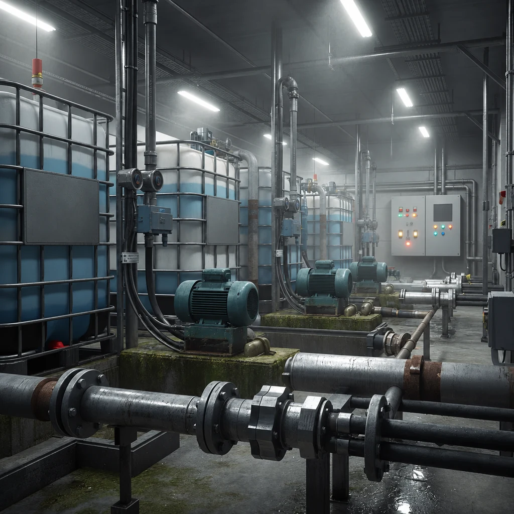
Why different plant zones need different entries
“Stainless IP68 gland” leaves important choices open. You still need the cable range, seal compound, wall joint and immersion conditions that fit the location. A chloride splash and a warm dosing chemical can challenge different parts of the same assembly.
Choose body materials from the actual corrosion mechanisms
No metal grade or polymer family is universally best for a wastewater plant. A stainless grade may be appropriate for one chloride and temperature condition but vulnerable to crevice attack in a trapped deposit or an incompatible cleaner. Nickel-plated brass may suit a controlled indoor duty but be a poor choice where the plating is damaged or the atmosphere attacks the exposed substrate. A polymer can avoid galvanic interaction yet still swell, embrittle, creep, lose UV resistance or exceed its temperature limit.
Chemical compatibility means suitability of a specified material or compound for the substance, concentration, temperature, contact mode and duration. I would use compatibility tables as screening aids only when they identify those variables and the formulation. Metal immersion tests also depend on solution composition, temperature, motion, duration, specimen condition and cleaning. Accelerated results may indicate a concern without predicting field life directly. (ASTM G31-21(2025)) Include these conditions in the qualification request.
| Body or accessory option | Where it can be useful | What must still be checked |
|---|---|---|
| Stainless steel of a named grade | Wet, outdoor or chemically exposed entries when grade-specific evidence matches | Pitting, crevice and stress-corrosion conditions; fabrication, passivation, deposits and mating metals |
| Nickel-plated brass | Controlled industrial areas with compatible atmosphere and cleaning | Plating continuity, cut edges, exposed brass, galvanic pair, chemical and temperature limits |
| Engineered polymer of a named formulation | Electrically insulating or chemically compatible duties within its mechanical limits | Creep, impact, UV, temperature, fire requirements, thread load and exact reagent compatibility |
| Coated or plated accessory | Isolation or surface protection in a documented assembly | Coating damage, edge exposure, washer and locknut compatibility, installation tools and repair limits |
For stress-corrosion cracking, check alloy, tensile stress and environment together. I would also include enclosure material, locknut, earth tag, washer and nearby fasteners. Assess bi-metallic corrosion across that whole stack. The gland body on its own cannot describe the mating-metal conditions.
In a wastewater-system H2S report, EPA notes that hydrogen sulfide can damage electrical contacts and other metal items. (EPA H2S air-sampling report) In its onsite wastewater design manual, EPA calls for electrical contacts and relays to be mounted outside a dosing chamber and for provisions to prevent gases from following electrical conduits into the control box. (EPA onsite wastewater design manual) Treat that information as process context, not as a gland material specification: the site still needs current measured conditions and a project-specific control strategy. The phrase “H2S present” does not select one mandatory alloy.
Match sealing compounds and cable jackets to the same chemicals
The compression seal is only one exposed polymer. The cable jacket, entry gasket, O-ring, shroud, thread seal product and any adhesive may encounter the same splash or vapour. A body that remains intact cannot compensate for a swollen jacket that no longer holds a stable sealing diameter, or an entry gasket that hardens and loses conformity after cleaning cycles.
ASTM D471-16a(2021) compares changes in rubber and rubber-like materials after liquid exposure. Its controlled accelerated tests may not correlate directly with field performance because service conditions vary. (ASTM D471 scope) I would specify the reagent or representative solution, concentration, temperature, immersion or one-sided contact, duration and recovery. Define the properties you will accept as well. Mass and volume change may not be enough: check hardness, tensile behavior, elongation, compression response, cracking and whether the conditioned part still seals the cable.
I would ask for the exact seal compound and cable-jacket grade before choosing EPDM, FKM, NBR, silicone or FFKM. Fillers, cure system, compounding and temperature all affect behavior. If several chemicals occur in sequence, test that order, including rinse water and drying. For example, a dosing skid may receive a concentrated drip during connection work, diluted washwater during cleanup and vapor between events. A room-temperature immersion in water does not represent that sequence.
Translate water exposure into testable conditions
Complete cable-entry configuration is the gland, cable, seals, thread or hole, wall, gasket, locknut and accessories assembled by a specified method. IEC 62444:2010 applies construction and performance requirements to complete cable glands as supplied. (IEC 62444 publication) I would also check the enclosure joint and field installation. Obtain test or declaration details for the intended cable and mounting arrangement.
IEC 60529 defines enclosure IP classifications. (IEC 60529 publication) I would choose the test from the project’s water exposure. Splash, jets, temporary immersion and the manufacturer-agreed IPX8 conditions are separate cases. A higher-looking number does not prove all of them. Jet testing does not establish chemical resistance. Immersion testing does not cover a hot detergent jet, pressure surge, damaged cable or liquid against an untested entry gasket.
For a stated flood level, the idealized static gauge pressure at the entry is:
where is static gauge pressure in pascals, is liquid density in kilograms per cubic metre, is local gravitational acceleration in metres per second squared, and is vertical liquid depth above the cable entry in metres. This calculation defines one load input. It excludes wave action, pump transients, jets, debris impact, internal enclosure pressure, capillary paths, temperature effects and exposure duration. Record the project values and units. A measurement result needs a documented calibration chain and associated uncertainty rather than an instrument label alone. (NIST metrological traceability guidance)
Example: low-mounted pump enclosure. Suppose the drawing puts the entry below the emergency water level. I would record vertical depth above that entry, liquid density and required duration, then calculate static pressure. Request evidence for at least that condition using the specified cable, gland, entry seal and panel. “Floodable” leaves too much for the supplier to assume, and the pressure calculation does not assign an IP code.
Compare these water paths with the washdown-versus-immersion criteria. Check entry-thread sealing when the mounting interface, rather than the cable seal, is the likely uncontrolled route.
Check the enclosure interface and cable route
I would measure the hole or tapped thread, wall thickness, coating, flatness and seating area before checking the mounting stack. The usable gland thread must accommodate the wall, gasket, washer, earth tag and locknut while meeting the maker’s engagement and seating instructions. Nominal male-thread length is not effective installed engagement. A curved, ribbed, corroded, painted or damaged face can stop the entry seal seating even with the correct thread size.
Use only accessories and sealants approved for the gland, enclosure and exposure. An unsuitable compound may attack a polymer, contaminate an elastomer, insulate a bonding path, alter tightening friction or prevent seating. I would check shroud drainage too: without a drainage path, a shroud can retain chemicals. Where allowed, orient and route the entry to reduce pooling while respecting bend radius, internal clearances and hazardous-area instructions.
Support the cable independently when route weight, vibration, maintenance handling or hydraulic movement can load the gland. Leave a drainage arrangement only if the enclosure design and site rules permit it. Do not create an unsealed low point or a sharp drip loop that violates minimum bend radius. The cable schedule should state outer diameter tolerance, ovality, jacket material, braid or armour construction where applicable, operating temperature and expected movement at the gland.
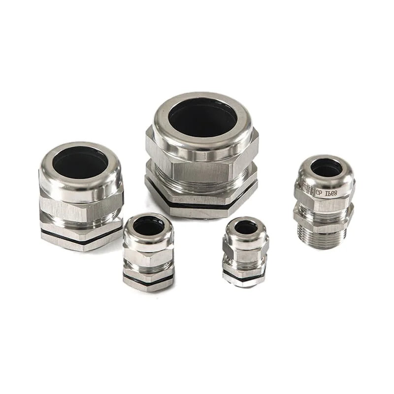
Apply hazardous-area requirements only where classification calls for them
Hydrogen sulfide is a toxic and flammable gas, and wastewater-treatment workers are among the groups that may be exposed. (NIOSH hydrogen-sulfide overview) This personnel hazard must be handled through the site safety system, monitoring and work controls. It does not by itself prove that every wastewater enclosure is in an explosive atmosphere or that a conventional gland can be upgraded by adding an “Ex” label.
Where the site’s competent assessment classifies a hazardous location, use the gas or dust group, temperature class, ambient range, protection concept and required zone or division. IEC 60079-14:2024 covers design, selection, installation and initial inspection of Ex electrical equipment in or associated with explosive atmospheres. (IEC publication) I would compare the gland certificate, schedule, marking and instructions with the cable, enclosure protection concept, barrier or sealing arrangement, thread, ambient limits and installation method. Keep toxic-gas controls separate from explosion-protection certification.
Check how the exposed assembly performs
I would build qualification around the failure mechanisms identified for the location. Where chemicals cause ageing, condition the actual seal, cable jacket, entry gasket and body material under a justified exposure. Then check affected functions: cable retention, sealing, ingress, thread or locknut security, electrical continuity where required, and visual or dimensional acceptance. Add temperature cycling, vibration and UV stages when they represent the exposure envelope.
Check the conditions most likely to limit fit. A small cable may provide less seal compression; a large cable may need more closure load. A thick panel or accessory stack can reduce thread engagement, and immersion may change jacket dimensions. These differences explain why a result for another cable or mounting arrangement may not apply.
| Qualification item | Record before testing | Inspect or measure after conditioning |
|---|---|---|
| Chemical exposure | Reagent, concentration, temperature, flow or vapour, duration, sequence and specimen | Mass/dimension where relevant, surface attack, cracks, hardness or mechanical properties, seal function |
| Water exposure | Splash, jet or immersion method; depth/pressure, duration, liquid and orientation | Ingress acceptance for the represented assembly and condition of every entry path |
| Cable fit and retention | Cable identity, diameter limits, jacket, preparation and support | Slippage, jacket damage, seal position and closure condition |
| Enclosure entry | Hole/thread, wall, coating, gasket, locknut and accessories | Seating, leakage path, loosening, corrosion and electrical duty where applicable |
| Environmental sequence | Temperature, vibration, UV, deposit and cleaning order | Functional re-test and any irreversible change |
Compare the tested cable, seal and mounting arrangement with yours. A smooth laboratory plate differs from a coated field enclosure, and a different cable can change contact with the seal. Those changes matter even when the gland body and stated IP code are the same.
Install, inspect and maintain by trigger
Make the equipment safe and follow the site permit before touching the entry. I would first verify the part number, marking, applicable certificate, cable, seals, accessories and instruction revision. Check the jacket for cuts, flattening, deposits and chemical softening. Clean the cable and seating face by an approved method. Then assemble in order, support the cable, use the manufacturer’s closure method, seat the entry seal and record the finished installation.
I would set inspection intervals from risk, condition and events. A frequently washed entry with chemical splash, vibration or difficult access needs a different review from a dry room. Add an inspection after flooding, an abnormal spill, cable movement, enclosure work, a nearby failed entry, a cleaning change or an unexplained trip. Use the structured visual inspection steps while recognizing that exterior condition cannot prove an internal seal is sound.

| Observation | Immediate question | Controlled next action |
|---|---|---|
| Deposit, stain or discoloration | Is the source a process chemical, corrosion product, dirt or cleaning residue? | Photograph and identify the substance; do not wipe away diagnostic evidence until permitted |
| Cracked, swollen or hard seal/jacket | Did chemistry, heat, UV, compression or movement exceed the approved condition? | Isolate as required and compare with the material and exposure record |
| Loose body, locknut or cable movement | Is the entry interface, closure or external support compromised? | Follow the safe rework instruction; do not tighten blindly |
| Moisture inside the enclosure | Which route is supported: cable seal, entry seal, enclosure joint, another opening, cable core or condensation? | Preserve the as-found state and test paths separately under an approved method |
| Flood or washdown beyond specification | Which depth, duration, pressure, temperature or chemical exceeded the qualified condition? | Quarantine or inspect affected entries and repeat the defined acceptance checks |
Conclusion: choose for the location and exposure
My selection starts with the tagged entry and its local exposure. Connect chemicals, water scenario, gas classification, temperature, cable, enclosure interface and maintenance access to that location. Those details decide whether a particular stainless, brass or polymer body and seal compound are suitable. “Wastewater duty” alone does not choose a grade.
A chemical, cleaning or flood-condition change can make a previously suitable entry inadequate. Recheck the affected body, seals, jacket and mounting joint when those conditions change. The material name and IP code are useful starting points; suitability depends on how the whole entry performs at that location.
FAQs about cable glands for wastewater treatment plants
Does every wastewater treatment plant cable gland need to be stainless steel?
No. A named stainless grade may suit many wet or corrosive locations, but it is not a universal requirement. Compare the exact metal, polymer, coating, seals, cable jacket and mating enclosure against the chemicals, temperature, deposits, UV, water and mechanical loads at that entry. Also check crevice and galvanic conditions, fabrication, surface treatment, thread load and qualification evidence.
Is IP68 always required in a wastewater treatment plant?
No. Select the water test from the actual location and project rules. A dry indoor entry, a washdown enclosure and an entry below an emergency flood level have different exposure scenarios. For an IPX8 claim, obtain the stated immersion conditions and represented configuration. Verify cable seal, entry seal, enclosure, mounting and installation together.
Which seal material is best for chlorine or sodium hypochlorite areas?
There is no reliable answer from elastomer family alone. Specify the exact chemical, concentration, temperature, vapour or liquid contact, duration, sequence and cleaning rinse. Then compare the exact seal compound and cable jacket using suitable compatibility data and, where needed, conditioning followed by seal and mechanical tests on the intended assembly.
Do hydrogen sulfide conditions require an explosion-protected cable gland?
Use the site’s competent hazardous-area classification. Hydrogen sulfide creates serious toxic and flammability hazards, but its possible presence does not classify every room or select a gland by itself. Where an explosive atmosphere is classified, match the gland certificate, protection concept, gas group, temperature class, ambient range, cable, barrier arrangement, thread and installation instructions.
What should be inspected after a wastewater enclosure has flooded?
Make the equipment safe, document the water level, liquid, duration and as-found condition, and identify every possible entry path. Inspect the cable, gland, seals, entry gasket, locknut, enclosure joints and internal terminations under the approved procedure. Compare the event with the qualified condition, replace non-reusable or damaged parts, and repeat the defined functional checks before returning the equipment to service.
Sources and technical references
- IEC 62444:2010, Cable glands for electrical installations, accessed 2026-09-13.
- IEC 60529, Degrees of protection provided by enclosures, accessed 2026-09-13.
- ASTM D471-16a(2021), Standard Test Method for Rubber Property: Effect of Liquids, accessed 2026-09-13.
- ASTM G31-21(2025), Standard Guide for Laboratory Immersion Corrosion Testing of Metals, accessed 2026-09-13.
- US EPA, Crossett, AR Hydrogen Sulfide Air Sampling Report (2017), accessed 2026-09-24.
- US EPA, Design Manual: Onsite Wastewater Treatment and Disposal Systems (1980), section 8.3.4.1, accessed 2026-09-24.
- NIOSH, Hydrogen Sulfide, accessed 2026-09-13.
- IEC 60079-14:2024, Electrical installation design, selection and installation of Ex equipment, accessed 2026-09-13.
- NIST, Metrological Traceability: Frequently Asked Questions and Policy, accessed 2026-09-13.