

EMC cable glands connect cable screens to conductive enclosures. EMC means electromagnetic compatibility: controlling emissions and maintaining operation amid interference. I check the complete path from screen to contact, body, entry joint, and wall. The exact gland may also provide retention and sealing, with separate evidence for those functions. A metal body alone cannot establish the EMC result.
I trace that installed path, record the conditions behind the performance data, and check that assembly preserves the contacts, seals, and retention. This guide applies to shielded industrial cables entering conductive enclosures. Cable fit still needs its own sizing check.
Key takeaways
- Match the gland’s contact element to the cable’s actual braid, foil or combined screen construction.
- Keep screen contact circumferential, short and mechanically stable at the enclosure boundary.
- Treat the environmental seal and the screen-contact path as separate functions that must both be correct.
- Compare transfer-impedance or screening-attenuation data only when the specimen, frequency range, termination and test method are stated.
- Verify the assembled path before equipment-level emission and immunity testing.
What an EMC cable gland does at the enclosure boundary
An EMC cable gland is an entry device with a conductive screen-termination path between shielded cable and enclosure. It may use spring fingers, a cone, a sleeve, or another specified contact. The product can also seal and retain the jacket and seal the entry. I check those separate interfaces against their assigned functions.
IEC 62444:2010 covers complete-gland construction and performance. An EMC claim also needs the screen, contact shape, mounting, frequency, and measurement method. I follow the physical path across each joint. A contact on the insulating jacket cannot reach the screen. A braid contact may still lead to paint, a loose locknut, an insulating adaptor, or a long pigtail—a narrow lead from the screen. Each changes the installed path. The EMC shielding primer helps define the equipment’s requirements. Then check the cable entry as one interface within that design.
EMC conformity belongs to the apparatus or installation under its applicable rules. The UK guidance on the Electromagnetic Compatibility Regulations 2016 requires limited disturbance and adequate immunity for intended use. I start with market and product requirements, then assign screen contact, environmental sealing, and retention to the entry. A gland supports that design without independently establishing the equipment result.
The five interfaces in the screen path
I follow five interfaces: screen, contact, body, entry connection, and enclosure wall. Inspect from both ends of the route. A sound contact cannot correct a break at the next joint. The jacket seal remains a separate environmental boundary.
The drawing shows a common spring-contact concept. I use the chosen maker’s drawing for actual parts, preparation, and assembly. Identify the screen contact, jacket seal, thread, and locknut. Check where the contact closes and which hardware joins the body to the wall. Compare prepared-screen diameter with its contact range; it can differ from jacket diameter. Cone and sleeve designs need the same interface checks even with different shapes. Record contact and seal positions before closing the enclosure. Check that support and permitted movement leave the contact centred on the intended screen.
Cable construction determines whether the contact can work
I inspect the cable datasheet and a cut sample. Record diameter and tolerance, jacket, screen type, stated braid coverage, foil orientation, drain wire, armour, bedding, and inner sheath. The contact must reach the intended layer without conductor damage or unstable screen edges. A copper braid generally suits circumferential spring or cone contact better than delicate foil alone. Foil can tear or fold, and its conductive face may face inward. A drain wire may provide a low-frequency connection while higher-frequency control needs broader contact. Use the cable and gland instructions for the exact build rather than one strip length for every cable.
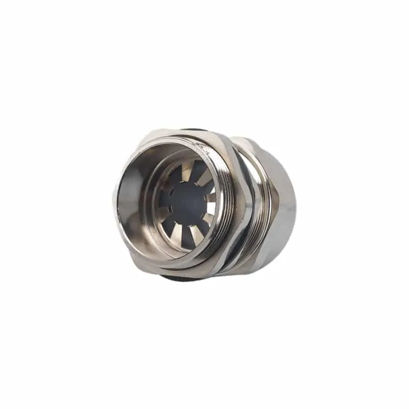
I check jacket sealing separately from screen contact. Excess jacket removal can place the seal on braid, foil, bedding, or a layer transition. This can compromise sealing and retention even if the electrical contact appears sound. The EMC gland selection checklist combines cable construction, exposure, and entry checks.
Contact geometry matters more as frequency rises
A long narrow pigtail can show direct-current (DC) continuity while adding inductance and impairing high-frequency contact. A short connection around the circumference keeps the transition broad. I record that geometry with the performance data. IEC 62153-4-10:2015+A1:2020 uses a double-coaxial method for feed-through and gasket transfer impedance or screening attenuation. Its result belongs to a defined specimen and frequency-dependent method. The transfer-impedance test-data checks cover the curve, fixture, and specimen behind a claim.
Transfer impedance relates unwanted voltage on the screened side to current outside the screen, per unit length or for a defined component. Screening attenuation expresses attenuation in decibels under a specified setup. I compare the same property, units, frequency range, fixture, specimen, termination, and uncertainty. Check that the curve covers the equipment’s failed or demanding port frequencies. The two measurements cannot be exchanged as labels.
The equipment standard determines final acceptance. IEC 61000-4-6:2023 covers immunity to conducted radio-frequency (RF) disturbance from 150 kHz to 80 MHz. Product committees determine applicability, levels, and performance criteria. I use the gland data as component evidence, not as the source of those equipment limits.
Select a gland from the required path, not from the body material
I establish the applicable product EMC standard, disturbance, ports, frequencies, and acceptance criteria first. Then match cable and entry to a documented contact design. Check jacket sealing, entry sealing, retention, and materials separately. The shortlist should match the screen and mounting used in the cited EMC test. Recheck changed contacts, finish, locknuts, preparation, or fixtures before extending an earlier result.
| Selection question | Record to compare | Reject when |
|---|---|---|
| What conductive layer is terminated? | Cable drawing, screen construction and preparation detail | The contact cannot reach the intended layer without damage |
| How is 360-degree contact maintained? | Contact type, diameter range and assembly section | Contact range omits the prepared screen diameter |
| How does the body meet the enclosure? | Thread or clearance hole, locknut, coating and bonding detail | An insulating layer remains in the intended conductive path |
| What environmental seal is used? | Jacket diameter range, seal material and entry-face seal | The seal lands on braid, foil or an irregular transition |
| What performance is claimed? | Property, curve, frequency, specimen and test method | A single dB or resistance value lacks test conditions |
| What movement occurs? | Support, bend, vibration and service-access plan | Cable load can disturb screen contact or seal compression |
I choose grade and finish for corrosion, loads, temperature, and compatibility. Conductivity alone cannot define frequency response or assembled bonding performance. The material and grounding comparison separates bulk conductivity from contact performance.
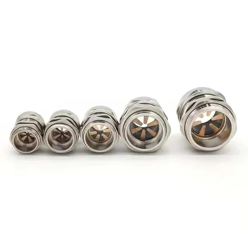
Install the screen contact and environmental seals as separate steps
I de-energize under the approved procedure before opening the enclosure or preparing cable. Match the gland, loose parts, and current drawing. Inspect the jacket for shape, damage, debris, and old compression marks. Check the enclosure before cutting: threaded walls, clearance holes, and adaptors can put contacts and seals in different places. Keep metal chips, loose braid, and removed coating away from conductors and seals.

- Confirm the entry. Check thread standard, size, pitch, hole geometry, wall thickness, coating and the specified entry seal. If the enclosure thread identity is uncertain, resolve it against the PG, metric and NPT comparison.
- Mark from a fixed reference. Use the gland drawing to place the jacket cut and screen-contact zone. Account for conductor reach and the required straight cable length outside the gland.
- Expose the screen cleanly. Remove the jacket without nicking braid wires, foil, drain wire, bedding or core insulation. Keep loose strands and metal swarf out of the seal and enclosure.
- Form the specified screen interface. Fold, trim or position the screen exactly as the contact design requires. Keep the contact band even around the circumference.
- Assemble the gland. Seat the contact, seal and body in their correct order. Prevent cable rotation from twisting the screen or inner conductors.
- Complete the enclosure connection. Prepare the mounting surface and fit the specified locknut, washer or bonding hardware. Restore corrosion protection around exposed metal without insulating the intended contact path.
- Tighten to the product instruction. Use the stated tool and endpoint. Avoid generic torque values; size, material, seal, thread and lubrication affect the required setting.
- Support and inspect. Route the cable so weight and bend force do not work the gland. Confirm the seal zone, screen zone and entry joint stayed in position.
IEC TR 61000-5-2:1997 provides EMC earthing and cabling guidance. Exact cable, gland, and equipment instructions determine preparation. For variable frequency drives (VFDs) and instrumentation, I use the shielded-cable gland specification checks for drive, motor, and signal routes.
Verify the path in layers
I verify visible assembly, then component measurements, then equipment EMC. Photograph the prepared screen and entry where permitted. Record identities, dimensions, contact position, hardware, tightening endpoint, and coating changes. A low-resistance check can reveal an open or unstable joint. Define instrument, lead compensation, probe points, test current, acceptance limit, and equipment state before interpreting it. The check cannot reproduce transfer impedance or equipment emissions and immunity. A controlled, safe movement check may reveal intermittent contact where the procedure permits it.
For industrial equipment, IEC 61000-6-2:2016 is a generic immunity standard used when no relevant dedicated product or product-family immunity standard exists. IEC 61000-6-4:2018 serves the corresponding generic emission role for industrial environments. Determine the applicable product standard first; generic standards are not automatic substitutes.
Use this verification sequence:
- visual and dimensional confirmation of the prepared screen, contact zone, seal zone and enclosure entry;
- stable electrical contact checks at defined probe points;
- comparison with component data from the same gland, cable screen and mounting arrangement;
- emission and immunity testing of the complete equipment in its defined cable and operating configuration; and
- reinspection after testing, transport or service work that could move the cable or entry.
Diagnose a failed EMC result without replacing parts at random
When EMC performance changes, I preserve routing and equipment state before adjusting parts. Identify the disturbance, frequency, port, cable, and operating mode. Then inspect each screen-path joint. Look for contact on jacket, damaged foil, bundled braid, incorrect contact range, dirt, paint, insulating adaptors, or loose locknuts. Cable twist and loads reaching the termination also matter. A passing DC check with a poor high-frequency result calls for review of geometry, exposed screen, openings, and other coupling paths. Random tightening changes several inputs and can hide the cause.
I use the high-frequency signal-integrity checks for geometry-related faults. Correct the identified interface, restore routing, and repeat the same failed measurement under comparable conditions.
Conclusion
I select an EMC gland as part of the complete screen path. Match actual screen construction and panel interface to the contact method, sealing range, and performance record. Keep the frequency-dependent evidence with that installed configuration.
During assembly, I keep screen contact broad, short, and stable while preserving jacket and entry seals. Check visible geometry and electrical contact first. Then complete the equipment’s applicable emission and immunity tests.
FAQs about EMC cable glands
Is every metal cable gland an EMC cable gland?
No. An EMC gland needs a defined conductive termination from the cable screen through the gland and into the enclosure. A metal body around an insulated cable jacket provides no intentional screen contact. Check the contact design, compatible screen construction, assembly drawing and performance data for the exact configuration.
Does a continuity test prove EMC performance?
A continuity test can reveal an open or unstable conductive path at the chosen probe points. It does not reproduce frequency-dependent transfer impedance, screening attenuation, or complete equipment emission and immunity behavior. Use it as an installation check, followed by the component and equipment tests required by the application.
Should the cable screen be made into a pigtail inside the gland?
Use the termination specified for the cable and gland. A long, narrow pigtail adds inductance and changes the high-frequency transition, while a circumferential contact keeps the connection broad and short. Some drain-wire or low-frequency arrangements have different instructions, so the cable and equipment design still controls.
Can an EMC gland also provide an IP-rated seal?
Yes, when the exact gland, cable jacket, entry seal, enclosure and assembly are within the tested configuration. Screen contact and environmental sealing occur at different interfaces. Match the jacket diameter and seal material separately from the prepared screen diameter and contact element.
What performance data should accompany an EMC cable gland?
Look for the measured property, units, frequency range, test method, specimen identity, cable screen, preparation, mounting arrangement and result curve or limits. Also obtain the environmental, retention and entry information needed for the same installed configuration. A single resistance or decibel value without conditions is insufficient for comparison.
Sources and technical references
- IEC 62153-4-10:2015+A1:2020, transfer impedance and screening attenuation of feed-throughs and electromagnetic gaskets, accessed 2026-09-12.
- IEC TR 61000-5-2:1997, EMC installation guidance for earthing and cabling, accessed 2026-09-12.
- IEC 62444:2010, Cable glands for electrical installations, accessed 2026-09-12.
- IEC 61000-4-6:2023, immunity to conducted disturbances induced by radio-frequency fields, accessed 2026-09-12.
- IEC 61000-6-2:2016, generic immunity standard for industrial environments, accessed 2026-09-12.
- IEC 61000-6-4:2018, generic emission standard for industrial environments, accessed 2026-09-12.
- UK Office for Product Safety and Standards, Electromagnetic Compatibility Regulations 2016 guidance for Great Britain, accessed 2026-09-12.