

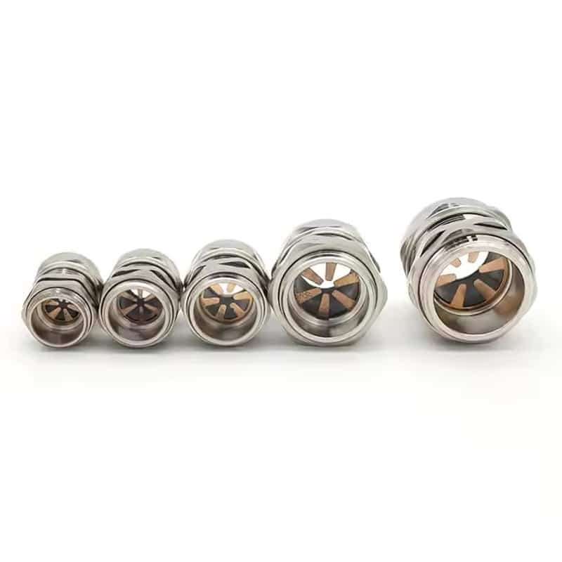
Struggling with EMI interference in your VFD systems? Frustrated by signal noise ruining your instrumentation readings? Poor cable gland selection is sabotaging your electrical performance.
Shielded cable glands must maintain 360-degree shield continuity while providing proper strain relief and environmental sealing – EMC-rated glands with conductive elements ensure optimal electromagnetic compatibility in VFD and instrumentation systems.
Last week, David called me in panic. His new VFD installation was causing havoc across the entire factory floor – production machines were randomly stopping, and quality control instruments were giving erratic readings. The culprit? Standard plastic glands that broke the shield continuity 😉.
Table of Contents
- Why Do Shielded Cables Need Special Glands?
- Which EMC Gland Design Works Best for VFD Applications?
- How Do You Maintain Shield Continuity in Instrumentation Systems?
- What Installation Mistakes Kill EMC Performance?
Why Do Shielded Cables Need Special Glands?
Think standard glands work fine with shielded cables? You’re setting yourself up for expensive EMI problems.
Standard cable glands break shield continuity at the enclosure entry point, creating EMI leakage paths that compromise system performance – EMC glands maintain continuous shielding through conductive elements and proper grounding.

The Physics of EMI Protection
Here’s what most engineers miss: a cable shield is only as good as its weakest link. When you terminate a shielded cable with a standard nylon or brass gland, you create a discontinuity in the Faraday cage1.
Standard Gland vs EMC Gland Performance
| Parameter | Standard Gland | EMC Gland | Impact |
|---|---|---|---|
| Shield Continuity | Broken at entry | 360° continuous | Critical |
| Transfer Impedance | >100 mΩ | <10 mΩ | Signal quality |
| Shielding Effectiveness | 20-40 dB | 60-80 dB | EMI suppression |
| Frequency Response | Poor >1MHz | Excellent >100MHz | VFD compatibility |
Real-World EMI Disasters I’ve Witnessed
Hassan’s Petrochemical Nightmare: His new control room was plagued by phantom alarms. Pressure sensors were triggering false readings every time the main VFD started. After switching to our EMC glands with proper shield termination, the interference dropped by 95%.
David’s Production Line Chaos: Random servo motor faults were costing $50,000 per hour in downtime. The root cause? Standard glands on encoder cables allowed VFD noise to corrupt position feedback signals.
Key EMI Sources in Industrial Environments:
- VFD switching frequencies: 2-20 kHz fundamental, harmonics to 100+ MHz3
- Servo drives: High-frequency PWM creates broadband noise
- Welding equipment: Intense EMI bursts across wide spectrum
- Radio transmissions: Mobile devices, wireless networks
- Lightning strikes: Transient electromagnetic pulses
Which EMC Gland Design Works Best for VFD Applications?
Not all EMC glands are created equal – choosing the wrong design can make your EMI problems worse.
Metal EMC glands with spring-finger contacts provide superior performance for VFD applications2, offering low transfer impedance and reliable 360-degree shield connection under vibration and temperature cycling.

EMC Gland Design Comparison
Spring-Finger Contact Design (Our Recommendation)
- Construction: Beryllium copper spring fingers
- Contact pressure: Consistent across temperature range
- Transfer impedance: <5 mΩ at 100 MHz
- Best for: VFD motor cables, servo systems
Compression Ring Design
- Construction: Conductive rubber or metal ring
- Contact pressure: Decreases with age/temperature
- Transfer impedance: 10-20 mΩ at 100 MHz
- Best for: Fixed installations, low-vibration environments
Mesh Grounding Design
- Construction: Conductive mesh sleeve
- Contact pressure: Variable, depends on installation
- Transfer impedance: 15-30 mΩ at 100 MHz
- Best for: Large diameter cables, retrofit applications
Bepto’s EMC Gland Technology
At Bepto, we’ve developed our EMC glands specifically for harsh industrial environments:
Technical Specifications
| Feature | Specification | Benefit |
|---|---|---|
| Material | Nickel-plated brass body | Corrosion resistance |
| Contact System | Beryllium copper springs | Long-term reliability |
| Temperature Range | -40°C to +100°C | Industrial environments |
| Vibration Rating | 10G, 10-2000Hz | Mobile equipment ready |
| IP Rating | IP68 | Complete environmental protection |
Real Performance Data
David’s VFD installation saw these improvements after switching to our EMC glands:
- Motor bearing currents: Reduced from 15A to <2A
- Encoder noise: Signal-to-noise ratio improved 40dB
- System uptime: Increased from 85% to 99.7%
Selection Criteria for VFD Applications:
- Cable shield type: Braided, foil, or combination
- Operating frequency: VFD carrier frequency + harmonics
- Environmental conditions: Temperature, vibration, chemicals
- Installation method: Panel mount vs. direct burial
- Maintenance access: Removable vs. permanent installation
How Do You Maintain Shield Continuity in Instrumentation Systems?
Instrumentation signals are incredibly sensitive – even microvolts of noise can corrupt critical measurements.
Instrumentation EMC glands must provide ultra-low transfer impedance (<1 mΩ) and maintain shield continuity from sensor to control room while accommodating small cable diameters and multiple conductors.
Instrumentation-Specific Challenges
Signal Integrity Requirements
Instrumentation systems demand much tighter EMC performance than power applications:
| Application | Acceptable Noise Level | Required Shielding |
|---|---|---|
| 4-20mA Current Loop | <0.1% of span | 60+ dB |
| Thermocouple | <0.1°C equivalent | 80+ dB |
| RTD/Resistance | <0.01Ω equivalent | 70+ dB |
| High-Speed Data | <1% bit error rate | 90+ dB |
Multi-Conductor Cable Considerations
Hassan’s refinery taught me this lesson. They had 24-pair instrumentation cables where each pair needed individual shielding plus an overall shield. Standard EMC glands couldn’t accommodate this complexity.
Our Instrumentation EMC Solution
Modular Shield Termination System
- Individual pair shields: Terminated to separate contact rings
- Overall shield: Connected to main gland body
- Drain wires: Dedicated termination points
- Cable strain relief: Protects delicate conductors
Installation Best Practices
- Shield preparation: Strip outer jacket without nicking shields
- Drain wire routing: Keep as short as possible to gland body
- Contact pressure: Verify with torque specifications
- Continuity testing: Measure transfer impedance before energizing
Case Study: Petrochemical Control Room Upgrade
Hassan’s facility had chronic issues with analog input noise affecting their distillation column control. Here’s what we discovered:
Before EMC Glands:
- Temperature readings: ±2°C variation
- Pressure signals: 5% noise on 4-20mA loops
- Flow measurements: Unstable, frequent recalibration needed
After Our EMC Glands:
- Temperature stability: ±0.1°C
- Pressure signals: <0.1% noise
- Flow measurements: Rock-solid, annual calibration sufficient
Critical Installation Points:
- Grounding philosophy: Star vs. daisy-chain grounding
- Shield termination: Both ends vs. single-point grounding
- Cable routing: Separation from power cables
- Enclosure design: Proper EMC gaskets and bonding
What Installation Mistakes Kill EMC Performance?
Perfect EMC glands become useless with poor installation – I’ve seen million-dollar systems fail due to simple mistakes.
Common installation errors include inadequate shield preparation, poor contact pressure, missing ground bonds, and improper cable routing – following proper installation procedures ensures optimal EMC performance.
The Top 5 Installation Killers
1. Inadequate Shield Preparation
The Mistake: Cutting shield wires too short or damaging them during stripping.
The Fix: Leave 25mm of shield beyond the cable jacket, use proper stripping tools.
David learned this the hard way when his technician used a utility knife instead of proper cable strippers. Half the shield strands were severed, creating a high-impedance connection.
2. Insufficient Contact Pressure
The Mistake: Under-tightening gland components to “avoid damage.”
The Fix: Follow torque specifications exactly – typically 15-25 Nm for M20 glands.
3. Missing Equipment Grounding
The Mistake: Connecting shield to gland but not bonding gland to enclosure.
The Fix: Verify <0.1Ω resistance from cable shield to enclosure ground4.
4. Poor Cable Routing
The Mistake: Running shielded signal cables parallel to power cables.
The Fix: Maintain 300mm minimum separation, use perpendicular crossings5.
5. Mixing Ground Systems
The Mistake: Connecting instrumentation shields to noisy power grounds.
The Fix: Use separate clean ground systems for instrumentation.
Our Installation Verification Checklist
Before energizing any system with EMC glands, we verify:
| Test | Specification | Tool Required |
|---|---|---|
| Shield Continuity | <0.1Ω end-to-end | Digital multimeter |
| Transfer Impedance | <10 mΩ @ 100MHz | Network analyzer |
| Insulation Resistance | >100MΩ | Megger tester |
| Ground Bond | <0.1Ω to enclosure | Milliohm meter |
Hassan’s $2M Lesson
Hassan once had a contractor install 200+ EMC glands on a new unit. Everything looked perfect until startup – massive EMI problems throughout the facility.
The issue? The contractor had properly installed the glands but failed to bond them to the enclosures. Each gland was electrically isolated, making the shields useless. A $50 bonding strap per gland would have prevented weeks of downtime and rework.
Quality Control During Installation:
- Visual inspection: Check for damaged shields, proper seating
- Electrical testing: Verify continuity and impedance
- Documentation: Record test results for future reference
- Training: Ensure installers understand EMC principles
- Supervision: Have experienced personnel verify critical connections
Conclusion
Proper EMC gland selection and installation eliminates EMI problems in VFD and instrumentation systems, ensuring reliable operation and signal integrity.
FAQs About EMC Cable Glands
Q: Can I use standard metal glands instead of EMC glands for shielded cables?
A: No, standard metal glands don’t provide proper shield termination and can actually worsen EMI problems. EMC glands have specialized conductive elements that maintain 360-degree shield continuity with low transfer impedance.
Q: How do I know if my EMC glands are working properly?
A: Measure transfer impedance between cable shield and enclosure ground – it should be <10 mΩ at operating frequencies. Also check for reduced EMI emissions and improved signal quality after installation.
Q: What’s the difference between EMC glands for power cables vs. instrumentation cables?
A: Power cable EMC glands focus on handling higher currents and voltages with robust mechanical construction. Instrumentation EMC glands prioritize ultra-low noise performance and accommodate smaller, more delicate cables.
Q: Do I need EMC glands for all shielded cables in my facility?
A: Not necessarily – prioritize critical applications like VFD motor cables, servo systems, and precision instrumentation. Less sensitive applications may work fine with standard glands if properly grounded.
Q: How often should EMC glands be inspected or replaced?
A: Annual inspection is recommended for critical applications. Check for corrosion, loose connections, and degraded contact pressure. Quality EMC glands from manufacturers like Bepto typically last 10+ years with proper maintenance.
-
“Faraday cage”,
https://en.wikipedia.org/wiki/Faraday_cage. Explains how continuous conductive enclosures block electromagnetic fields. Evidence role: mechanism; Source type: research. Supports: Explains why a discontinuity in the Faraday cage compromises EMC shielding. ↩ -
“Cable Shielding and Terminations”,
https://incompliancemag.com/article/cable-shielding-and-terminations/. Analyzes different termination methods and their impact on high-frequency noise. Evidence role: mechanism; Source type: industry. Supports: Confirms that metal EMC glands with spring-finger contacts provide superior performance. ↩ -
“Variable-frequency drive”,
https://en.wikipedia.org/wiki/Variable-frequency_drive. Outlines the operational frequencies and harmonic distortions generated by motor drives. Evidence role: statistic; Source type: research. Supports: Validates that VFDs generate 2-20 kHz fundamental switching frequencies and high-frequency harmonics. ↩ -
“IEEE 1100 – Emerald Book”,
https://standards.ieee.org/ieee/1100/4030/. Recommended Practice for Powering and Grounding Electronic Equipment. Evidence role: statistic; Source type: standard. Supports: Provides the technical threshold for low-resistance shield grounding. ↩ -
“NFPA 79: Electrical Standard for Industrial Machinery”,
https://www.nfpa.org/codes-and-standards/all-codes-and-standards/list-of-codes-and-standards/detail?code=79. Establishes safety and separation requirements for industrial wiring. Evidence role: general_support; Source type: standard. Supports: Mandates the 300mm minimum separation and perpendicular routing for noise reduction. ↩
