

An M20 cable gland has a metric enclosure-entry thread with a nominal diameter of 20 mm. The full designation M20 × 1.5 adds a 1.5 mm thread pitch. I check that enclosure-side fit separately from the cable range: the number 20 describes the entry thread, not a 20 mm cable opening.
For selection, read three sets of dimensions together: the thread that enters the enclosure, the length available through the panel, and the cable diameter accepted by the seal. Two glands with the same M20 entry can differ in either of the other two.
Key takeaways
- M20 names a nominal metric entry-thread diameter.
- Keep the numeric pitch and interface standard on the drawing; M20 × 1.5 states the pitch explicitly.
- Use the gland variant’s cable range to match the complete finished cable OD interval.
- Check a tapped entry and a clearance hole with locknut as different mounting arrangements.
- Allow for the panel, washers and required engagement within the usable male-thread reach.
Decode the M20 cable gland designation
Nominal diameter is the size used to name the thread. In M20, it is 20 mm. Pitch is the axial spacing between corresponding points on adjacent threads. The 1.5 in M20 × 1.5 means 1.5 mm pitch; it is not a wall thickness, cable size or tightening allowance.
The IEC 62444:2010 scope covers complete cable glands with IEC 60423 metric entry threads. IEC 60423:2007 covers conduit and fitting thread dimensions. I record the full M20 × 1.5 entry designation and its interface standard together, so the receiving hole, locknut and gland are specified in the same system.
| Marking or dimension | What it describes | Where I use it |
|---|---|---|
| M20 | Nominal metric entry-thread diameter, 20 mm | Identify the enclosure-side size family. |
| × 1.5 | Thread pitch, 1.5 mm | Match the mating thread and determine ideal axial travel. |
| Usable male-thread reach | Available axial extent of usable thread from the defined mounting reference | Check the wall and accessory stack. |
| Cable range | Accepted finished cable outside diameters for that variant | Match the cable at the intended seal location. |
| Spanner size | Width across the specified wrench flats | Plan tool access and spacing between entries. |
This is why I keep the complete designation on replacement orders. “M20” is useful shorthand within a defined drawing system, but the pitch and interface details need to travel with the part when teams or suppliers change. The metric, PG and NPT thread guide explains the family differences.
A UK AAIB investigation, printed page 163 gives a practical example from an oil-filter installation. It distinguishes M20 × 1.5 from a 3/4 × 16 thread with a similar pitch but a different diameter. The mismatched filter could be tightened despite its reduced engagement. For a cable entry, the same fitting lesson applies: a partial start or apparent tightness is a poor substitute for matching the full thread definition.
Why a caliper reading is only part of thread inspection
Major diameter is the diameter over the external thread crests. A finished M20 thread can measure below the nominal 20 mm because the applicable thread limits define its actual size. Compare the measured dimension with the drawing’s limits, not with 20.000 mm as a universal acceptance value.
Pitch diameter describes an intermediate reference cylinder through the thread profile. It matters to the fit between the flanks. The NIST study of threaded-gauge measurement identifies the pitch-diameter cylinder as the reference datum and discusses the uncertainty of measuring it. A crest measurement and a pitch-leaf check therefore answer only part of the inspection task.
I use a pitch gauge to identify the likely spacing, then check the required dimensions and gauges for the interface. The external and internal fit limits, coating condition and usable length belong to the same drawing review. If a part binds early or rocks in the entry, inspect the mating threads before applying a wrench.
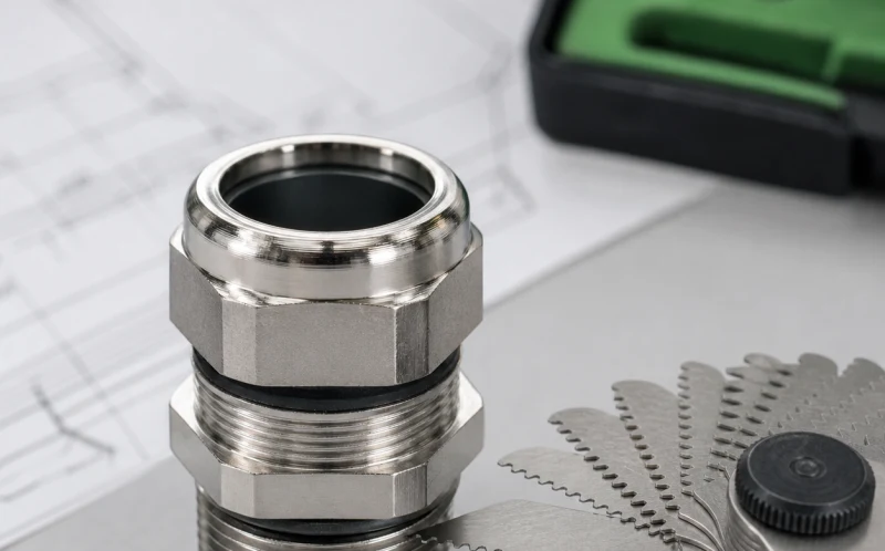
A set of thread-pitch leaves lies beside the metal entry component. Matching a leaf to the thread helps identify spacing; the drawing and specified gauges define the complete fit check.
Worked example: pitch and free axial travel
For a single-start thread, one full turn produces an ideal axial advance equal to its pitch. Suppose two matching M20 × 1.5 parts have 3.75 mm of free axial travel before their next contact. The ideal number of turns is:
Here, is the assumed free travel in millimetres and is the pitch in millimetres per turn. Two and a half turns correspond to 900°. This is a geometry example with matching, freely moving threads. Once a seal or shoulder contacts, use the product’s tightening instruction; the travel calculation does not set its final compression.
The M20 versus M20 × 1.5 guide covers pitch identification and mismatched threads in more detail. In this specification breakdown, I use the pitch calculation to understand motion and keep it separate from the strength and sealing checks.
Allow for usable thread and the panel stack
Usable thread is the full-form portion available for the intended mating engagement. Chamfers and runout contain incomplete thread, so the visible distance from shoulder to tip can overstate what the locknut or tapped boss can use. Locate the mounting reference and full-thread limits on the drawing before calculating the stack.
For a clearance-hole installation, the panel and any washer between the gland’s mounting reference and the locknut occupy axial space. The remaining full-form thread must meet the specified locknut engagement. For a tapped entry, check the female depth, shoulder clearance and any blind-hole bottom as well.
I measure axial projection from the drawing’s reference face to the thread end with the body supported and the tool aligned to the thread axis. I record runout and end chamfer separately. A long visible thread can still leave too little full thread after a thick wall or recessed entry is added.

Worked example: the same thread size, different mounting fit
Assume a panel is 5.0 mm thick and the specified face washer occupies 1.0 mm in its installed condition. The hypothetical assembly requires 4.0 mm of full-thread locknut engagement. Its minimum usable reach is:
In this simplified example, the stated usable reaches already allow for chamfers and runout, and the required locknut zone contains full-form thread. A 9.5 mm usable reach leaves 3.5 mm after the panel and washer: 0.5 mm short of the assumed requirement. A 12.0 mm reach leaves 6.0 mm, providing 2.0 mm beyond that requirement.
Both parts may be M20 × 1.5. The longer usable reach solves the stated stack problem; changing the thread’s nominal diameter is unnecessary if the remaining fit and performance checks pass. The actual gland and accessory drawings set the engagement requirement—4.0 mm is an input to this example, not a general M20 rule.
Choose the receiving-entry geometry
A tapped entry contains the female thread that mates with the gland. Match the family, nominal diameter, pitch and fit, then check the usable depth and lead-in. For a blind entry, leave the specified tip clearance so the gland reaches its seal seat before it bottoms. Inspect the shoulder land and use the intended face or thread seal.
A clearance hole is an unthreaded opening through which the male entry passes. A locknut retains the gland from the other side. Its hole diameter and tolerance must provide passage while preserving the specified sealing land and accessory support. I take those values from the gland and enclosure drawings. A nominal 20 mm thread designation is not, by itself, a hole-making instruction.
An adaptor or reducer joins two defined interfaces. Record each side’s thread, pitch and male or female form, then include its added length in the stack. Also check the new sealing surface and tool access. The entry-hole selection guide covers the receiving-opening details.
For a clearance-hole entry, I trial-fit the body, face washer, panel and locknut in their intended order. Leave the locknut loose during the fit check and support the cable separately. Check both sides for spanner access, nearby obstructions and enough usable thread before final tightening.

Match the cable range to the chosen M20 variant
Cable sealing range is the finished cable outside-diameter interval accepted by a specific gland variant and assembly. Start with the cable’s minimum and maximum OD, including its manufacturing tolerance. Both ends of that interval must fit within the gland’s declared range.
I then check the surface under the seal. The design may need a continuous round jacket, while ribs, ovality, armour, braid or a jacket transition change the contact. For screened or armoured constructions, compare each additional contact, clamp and seal diameter with the section drawing. The single- and double-compression guide explains those separate interfaces.
Continue the hypothetical panel example with a cable OD of 10.0–10.6 mm. Assume the three candidates below all have the correct M20 × 1.5 interface, the same specified 1.0 mm installed face washer, and compatible round-jacket construction. The 5.0 mm panel and 4.0 mm engagement requirement remain unchanged.
| Hypothetical M20 variant | Cable range | Usable reach | Cable fit at 10.0–10.6 mm | Full thread left after 6.0 mm panel/washer stack | Dimensional decision |
|---|---|---|---|---|---|
| A | 6.0–12.0 mm | 9.5 mm | Within range | 3.5 mm; short by 0.5 mm | Choose a longer usable reach. |
| B | 10.5–14.0 mm | 12.0 mm | The 10.0 mm minimum is below range | 6.0 mm; meets the assumed 4.0 mm requirement | Choose a suitable cable-range variant. |
| C | 6.0–12.0 mm | 12.0 mm | Within range | 6.0 mm; meets the assumed 4.0 mm requirement | Fits both dimensional checks. |
I found that C is the only candidate in this hypothetical comparison that fits both the cable and the mounting stack. A fits the cable but is too short; B reaches through the panel but misses part of the cable tolerance. Selecting only by the shared M20 label would hide both failure modes.
I would carry C forward to the application checks: body and seal material, jacket compatibility, retention, environment and the required installation method. The table makes a dimensional selection; the product’s declared performance still has to suit the duty.
Turn the designation into a complete specification
A useful M20 specification pairs the entry details with the exact gland variant and its intended cable. The following fields let the enclosure designer, installer and buyer work from the same assembly:
- Complete gland part number and the current drawing revision.
- M20 × 1.5 entry designation, interface standard and applicable fit limits.
- Usable male reach and required engagement, with reference faces identified.
- Tapped-entry details or clearance-hole diameter and tolerance.
- Panel thickness, sealing land, washer, locknut and any adaptor or earth tag.
- Cable designation, full OD interval, jacket profile and each extra armour or shield interface.
- Body/seal materials, required performance, tightening method and access clearance.
Ingress protection describes enclosure protection classified by the IP Code. The IEC 60529 scope concerns that enclosure classification. For a gland entry, select the stated cable and accessories, prepare the sealing land and follow the assembly conditions associated with the required protection.
I treat material, temperature, corrosion, retention, EMC and hazardous-area requirements as application selections alongside the dimensions. The M20 entry can be shared by products designed for very different duties. Read the relevant product data and approval conditions for the selected construction, then confirm that the installation has room for the body, spanners and cable bend.
Use the Cable Entry Glossary when a document uses entry thread, sealing range, clamping range or locknut inconsistently. If the exposure includes floodwater or pooling, the extreme-weather entry guide covers that separate duty assessment.
Conclusion
M20 tells me the nominal size of the metric enclosure-entry thread. I keep the pitch and interface standard with that name, then check the usable length through the panel and the cable range of the exact gland variant.
The worked comparison shows why those checks stay separate: a gland can fit the cable and still be too short, or fit the panel and miss the cable’s minimum diameter. Choose the variant that meets both, then confirm its materials, performance and installation conditions for the application.
FAQs about M20 cable gland specifications
Why can an M20 male thread measure slightly under 20 mm?
M20 is a nominal size. The applicable thread dimensions and tolerance define the finished external diameter. Compare the measurement with those limits and use the specified fit checks; a caliper over the crests does not assess the entire thread profile.
Can I install an M20 gland in a 20 mm punched hole?
Use the clearance-hole diameter and tolerance specified for the chosen gland and mounting arrangement. The opening must pass the male thread while supporting the required washer and sealing land. Panel thickness, hole finish and locknut access also affect the fit.
Is an M20 × 1.5 gland interchangeable with any part marked M20?
Match the full thread system, pitch and fit first. Then compare usable length, male/female form, sealing seat and accessory stack. A shared nominal diameter or a partial hand start leaves those other dimensions unresolved.
Which cable diameter fits an M20 gland?
Use the cable range for the exact gland variant. Both the minimum and maximum finished cable OD must fall within it, and the jacket profile and seal location must suit the design. Different M20 variants can accept different cable ranges.
Sources and technical references
- IEC 60423:2007 — Conduit and fitting thread dimensions, accessed 2026-10-29.
- IEC 62444:2010 — Cable glands for electrical installations, accessed 2026-10-29.
- IEC 60529 — Degrees of protection provided by enclosures (IP Code), accessed 2026-10-29.
- UK AAIB Bulletin 11/2006 — G-CCKF, oil-filter comparison on printed page 163, accessed 2026-10-29.
- NIST — Pitch Diameter Measurement of Threaded Gages Using a CMM, accessed 2026-10-29.