

Cable glands support functional safety by keeping safety-related cables secure, maintaining the enclosure boundary, and preserving any assigned screen or bonding connection. A failed entry can disturb a sensor signal, interrupt power, or expose several safety channels to the same water path. I start with the required safety action and trace how each entry could help or hinder it.
A Safety Integrity Level (SIL) describes the integrity of a defined safety function under the applicable standard. Installing an ordinary gland in a SIL-assessed system does not give that part the system’s rating. The useful design question is which cable-entry failures can prevent the function from acting, and how the design detects, prevents or accounts for them.
Key takeaways
- Trace sealing, retention, screen and bonding failures to the required safety action.
- Classify a fault using the actual circuit response: an open wire may trigger one system and disable another.
- Examine shared water paths, supports and maintenance actions before treating redundant channels as independent.
- Resolve a credible failure contribution through suitable data, analysis or design controls; missing data do not make it zero.
- Match installation, inspection and proof testing to the failure paths the safety design depends on.
SIL belongs to the safety function
Functional safety is the part of overall safety that depends on equipment or a system operating correctly in response to its inputs. A safety function is the defined action that achieves or maintains a safe state under stated conditions. A Safety Integrity Level (SIL) expresses a required or achieved integrity band for that function under the applicable standard and demand mode. It is not a quality grade for every nearby mechanical item.
The UK HSE functional-safety overview describes safety instrumented systems with sensors, logic and final elements. IEC 61508-1:2010 addresses electrical, electronic and programmable electronic systems that perform safety functions.
For a shutdown, I trace measurement, logic and actuation together with their wiring and power. A seal may protect transmitter terminals; retention may keep a conductor from being pulled free. Losing either protection can affect the required action.
Trace the entry from stress to safety-function effect
A failure path is the chain from a physical stress to a component defect and its effect on the safety action. I use that chain to distinguish a damaged part from a dangerous system failure. The same loose gland may cause a detected trip, leave a fault hidden until the next demand, or affect equipment outside the safety function. The circuit response and diagnostics determine the classification.
I work through four questions:
- What stress reaches the exact cable, gland, entry, and enclosure configuration?
- Which gland or interface function can be lost under that stress?
- What electrical, mechanical, or environmental condition then reaches the safety-related equipment?
- How does the defined safety function respond, and is that response detected before a demand?
I check what the moisture reaches: critical terminals, power wiring or a separate non-safety compartment. Drainage, separation and diagnostics may change the result. Follow the path far enough to identify the effect on the required action.
Worked example: three entry faults in a pressure trip
Consider a hypothetical high-pressure trip whose required action is to close a feed valve before the process exceeds its defined limit. Assume the transmitter, logic and valve form the safety function. If moisture entering through a cable seal causes the measured pressure to read low, the trip may miss a real demand. That is a dangerous path when diagnostics or other provisions do not reveal and manage the fault in time. Now change the fault: cable movement opens an input wire, and the configured circuit responds by closing the valve. For this specified pressure-protection action, the response is a trip rather than a missed demand. It may still interrupt production, and the wider process must tolerate that shutdown. The classification follows the configured response; it cannot be inferred from the word “loose.”
Now suppose two redundant pressure channels enter the same low-mounted box. Water reaching both channels through one enclosure boundary is a shared event. Counting two gland bodies as two independent protections would miss that path. I review whether separate enclosures, routes or a qualified barrier interrupt the actual exposure. If both routes still cross the same flooded trench, physical separation at the box alone has left a dependency in place. The safety assessment must address that remaining shared exposure.
Four entry functions protect the safety path
The installed entry may perform several jobs. I check each assigned job against the failure path, because a good environmental seal can still have a poor screen termination or inadequate cable support.
| Entry function | Credible loss | Safety-function question | What to check |
|---|---|---|---|
| Environmental sealing | Water, dust, or chemicals reach equipment | Can they bias, short, corrode, or disable a safety channel? | Complete entry and enclosure under relevant conditions |
| Cable retention | Cable moves, pulls out, or loads terminals | Can conductors open, short, or alter a sensor connection? | Exact cable, dimensions, installation, and mechanical load |
| Armour or screen termination | Metallic layer loses its intended contact | Can electromagnetic compatibility (EMC) disturbance or mechanical damage affect the channel? | Assigned function, contact geometry, frequency, and equipment response |
| Bond or enclosure interface | Conductive path opens or gains resistance | Does a protective or reference path depend on this joint? | Whole current path, wall, accessories, corrosion, and system design |
If the safety function depends on an electrical route at the entry, I review it separately. The grounding-diagnostic guide covers protective earth (PE), armour, screen, gland, enclosure, and protective-device paths. Here, the question remains: what happens to the required safety action if that particular route is lost?
EMC performance also needs more than a continuity beep or a metallic gland. The installed EMC shielding guide explains the source, coupling path, susceptible equipment, and contact geometry. Trace the disturbance to the affected signal, diagnostic response and required action.
Turn the required safety action into entry requirements
A safety requirements specification (SRS) is the controlled statement of what each safety function must do and under which conditions. The hazard analysis identifies the required risk reduction. The cable entry becomes relevant when a credible failure can alter those functional or integrity requirements.
Locate the entries used by each safety function and mark shared enclosures, plates, routes, exposures and drainage. A non-safety status cable may lie outside the boundary; redundant trip-signal cables need closer review when one event could affect both.
I turn that analysis into entry requirements: cable range, washdown exposure, route separation, assigned screen or armour connections, and any relevant diagnostic response or restoration time. Select the assembly against these conditions, then give installation and maintenance teams the configuration they must preserve.
Account for the entry in the safety model
The model boundary follows the safety function and its dependencies. Establish that boundary before choosing failure-rate data. IEC 61508-2:2010 covers elements within an electrical, electronic or programmable electronic safety-related system and connects design with installation, validation, operation, maintenance and modification. An entry that can disable a required signal or power path needs treatment in the safety assessment even when a convenient component rate is unavailable.
PFDavg is the average probability of a dangerous failure on demand for the relevant low-demand assessment. PFH is the average frequency of dangerous failure per hour used for the applicable high-demand or continuous-mode assessment. Their calculation depends on the architecture, failure modes, diagnostics, proof tests, repairs and dependencies. The IEC 61508-6:2010 overview identifies examples of hardware-failure probability calculations and a method for hardware-related common-cause effects. Select the method for the complete function and demand mode.
A cable entry may be represented in different ways within that assessment:
- An explicit contributor: model the relevant failure modes with applicable rates, detection, repair and test assumptions.
- Part of an assessed assembly: check whether subsystem data already include the cable entry and its failure effects. Adding the same contribution again would double-count it.
- An environmental or installation condition: justify how the specified design and lifecycle controls maintain that condition, including what happens if the protection degrades.
- A dependent failure path: account for a common exposure or practice that can affect several channels together.
I check the inclusion boundary of existing subsystem data before adding a separate gland term. Then I trace the remaining failure paths. Missing or mismatched data leave an unresolved contribution; they do not justify assigning zero or moving a credible danger outside the assessment. Obtain suitable data, use a justified analysis with defensible uncertainty bounds, or change the design to remove or control the path. Resolve that issue before crediting the function with its required integrity.
Match reliability information to the actual failure
A failure definition states the event counted in a reliability dataset. A seal leak, a released cable and a failed shutdown action are different events. I compare that definition with the effect the model needs to represent. A rate for cosmetic corrosion, for example, does not describe the probability of an undetected pressure-input error.
Check the population and conditions behind the data:
- Gland family, sizes, seal materials, accessories and installed configuration.
- Cable construction, diameter distribution, assembly method and loading.
- Operating time or demands, environment and useful-life period.
- Failure criterion, detection method and reporting threshold.
- Treatment of units still operating when observation ended, zero-event samples and uncertainty.
- Separation of random hardware failures from systematic errors and shared causes.
A failure modes, effects and diagnostic analysis (FMEDA) organizes failure modes, their effects and diagnostic assumptions. Check the underlying data and coverage. If the seal, environment or failure definition differs from the installation, justify its applicability, obtain better data or revise the design. Keep unresolved contributions visible in the assessment.
Separate the cause as well as the channels
Common-cause failure occurs when a shared cause produces failures in multiple items. I check shared paths as well as separate gland bodies. Separate glands on a low-mounted plate may share a flood path. Identical seals may share chemical incompatibility or low-temperature behavior. An unsupported bundle may load several entries. One maintenance action or repeated installation error may affect the whole population.
HSE’s control-systems guidance identifies shared equipment, utilities, environment and maintenance as matters for independence review. For cable entries, I apply that principle to the physical route:
| Shared mechanism | Misleading assumption | Better system treatment |
|---|---|---|
| One enclosure or gland plate | Each entry sees an independent environment | Analyze the shared ingress and drainage boundary |
| Same material and chemical | Redundant seals age independently | Qualify compatibility and consider diversity only when evidence supports it |
| Common cable route or support | Each gland receives an independent load | Control routing and mechanical loads before the entry |
| Repeated installation method | Assembly errors are random | Improve instructions, training, tooling, and verification at the process level |
| One maintenance intervention | Only the targeted channel changes | Control simultaneous disturbance and post-work restoration |
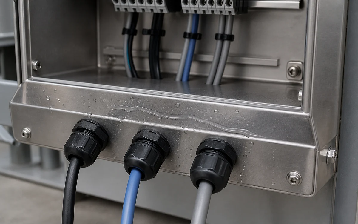
Three separate cable entries share the same wet stainless-steel gland plate and surrounding enclosure boundary.
A walkdown should follow the water route beyond the gland nut: plate joints, unused holes, enclosure seams, cable drip paths and drainage may connect entries that appear separate from the front.

I choose diversity when it interrupts an identified shared cause. For example, an alternative seal compound may help with a specific chemical exposure if compatibility is established for both the compound and the installation. Changing materials also changes assembly and maintenance needs. Review those consequences alongside the intended reduction in shared vulnerability.
Select the assembly for its environmental duty
Ingress, retention, material, vibration and temperature performance help preserve the conditions required by the safety design. IEC 62444:2010 provides requirements and tests for complete glands as supplied. Match that product evidence to the cable, entry, accessories and enclosure used in the installation. Then address service exposures outside the tested configuration.
IEC 60529 classifies enclosure ingress protection under defined tests. The IP-rating selection guide explains exposure selection and matching the cable, gland, enclosure entry, accessories, and test assembly. For immersion service, compare the declared test conditions with the actual depth, duration and pressure. Check chemical exposure, temperature cycling and maintenance state separately where they affect the seal or enclosure.
Hazardous-area suitability answers a separate question. Ex means explosion protection. The hazardous-area gland selection guide covers classification, protection concept, marking, certificate schedule, cable, and entry matching. Meet the applicable Ex requirements alongside the functional-safety requirements. The explosion-protection assessment and the safety-function assessment address different failure consequences and need their respective scope checks.
Preserve the entry through installation and maintenance
I check the cable range, part order, entry interface, accessories, preparation and model-specific tightening instructions before accepting the assembly. Support and route the cable so unassigned loads do not reach the gland. Review changes to cable, enclosure, material, washer, adapter, paint, or work method when they could invalidate the assumption.
Then target maintenance at the failure modes relevant to the function. A visual inspection may find cracking, corrosion, movement, missing parts, or leakage. It may miss internal water, marginal screen contact, conductor strain, or a vibration-only fault. A proof test is a planned test intended to reveal dangerous failures left undetected during normal operation. Its claimed coverage depends on the failure modes the procedure actually reveals. An electronic transmitter simulation that bypasses the field wiring also bypasses faults in that path. Add the appropriate inspection or functional test for those failure modes rather than treating a successful simulation as proof of the entire installed loop.
I set activities and intervals from the function assumptions and failure mechanisms, considering environment, diagnostics, operating history and instructions. HSE’s control-systems guidance calls for proof-test procedures with pass/fail criteria, safe execution and suitable end-to-end coverage. Before disturbing an entry, apply the site’s isolation and work-control procedure. Record the condition found where it helps diagnose degradation, restore the specified assembly and verify the affected functional path before return to service.
Conclusion
Cable glands contribute to functional safety by preserving the physical conditions that sensing, logic, power and final elements depend on. I prioritize the failure paths that could prevent the required action: moisture reaching a critical circuit, cable movement opening a necessary connection, a failed screen or bond, and one shared event affecting redundant channels.
Define those paths, select and install the entry for its duty, and verify that inspection and testing cover the relevant effects. Use the system’s architecture and applicable reliability information to account for the contribution. Resolve missing data or inadequate controls before crediting the required integrity. This makes the gland’s role clear within the safety function and gives maintenance teams specific conditions to preserve.
FAQs about cable glands and functional safety
Does installing a gland in a SIL-assessed system give it a SIL rating?
SIL concerns the defined safety function; installation does not transfer it to an ordinary gland. Check any supplied component assessment for its exact scope and conditions, then evaluate its role in the complete function.
Must cable-gland failures be included in PFDavg or PFH?
Account for credible effects within the safety assessment. Check whether subsystem data already include them before adding a separate term. Missing reliability data require resolution; they do not make a failure contribution zero.
Does an IP66 or IP68 result prove suitability for a safety instrumented system?
An IP result supports ingress protection for its tested configuration. Match that configuration to service exposure and assess retention, electrical interfaces and channel independence. The complete safety-function assessment establishes the integrity claim.
Can separate glands share a common-cause failure?
Yes. Entries may share a flood route, chemical exposure, cable support or maintenance action. Separate or control that cause as well as the gland bodies.
Sources and technical references
- IEC 61508-1:2010 — Functional safety, Part 1: General requirements, accessed 2026-10-28.
- UK HSE — Functional safety and safety instrumented systems, accessed 2026-10-28.
- IEC 61508-2:2010 — Requirements for E/E/PE safety-related systems, accessed 2026-10-28.
- IEC 61508-6:2010 — Guidelines on the application of IEC 61508-2 and IEC 61508-3, accessed 2026-10-28.
- UK HSE — Control systems: independence and proof testing, accessed 2026-10-28.
- IEC 62444:2010 — Cable glands for electrical installations, accessed 2026-10-28.
- IEC 60529 consolidated version — Degrees of protection provided by enclosures, accessed 2026-10-28.