

Brass vs. aluminum cable glands have no universal thermal winner. I compare the exact alloys in like-for-like assemblies. An aluminum alloy may conduct heat better than a brass alloy, but installed temperature also depends on shape, mass, finish, contact interfaces, cable losses, enclosure, ambient conditions, and airflow. Those inputs determine which complete product suits the duty.
Key takeaways
- Compare exact alloy and temper or condition, not the family names “aluminum” and “brass.”
- Bulk conductivity is one property inside a larger thermal path; it is not a complete-gland temperature result.
- Cable ampacity cannot be increased by a material substitution alone without a valid cable-system calculation or test.
- Seals, cable jackets, plating, threads and mounting interfaces may set the usable temperature boundary before the metal body does.
- A useful comparison fixes the gland geometry, cable, enclosure, assembly torque, heat input and environment.
Comparing brass vs. aluminum cable glands requires a boundary
Thermal performance means the behaviour being required under a defined temperature duty. I name the outcome first: low surface temperature, stability through cycling, reduced mass, dependable threads, or compatibility at a hot panel. A lightweight enclosure and a vibrating panel may favour different features. Aluminum and brass each contain many alloys. Temper or material condition, cold work, casting or machining, porosity, and finish can change thermal and mechanical behaviour. Pure aluminum data cannot represent every production alloy, and one copper-zinc grade cannot represent all brass glands. I therefore ask which complete configuration meets the temperature, sealing, retention, corrosion, and installation requirements. Conductivity helps answer part of that question.
Start with the exact material system
Bulk thermal conductivity describes heat conduction through a homogeneous specimen under stated conditions. It excludes gland walls, threads, seals, finish, and enclosure contacts. ASTM E1225 measures homogeneous opaque solids by a guarded comparative steady-state method. Its result does not qualify a finished gland. The NIST thermal-conductivity report on relatively pure aluminum is also material reference data. I keep values with their alloy, condition, temperature, and measurement basis. Density, specific heat, and conductivity describe different responses, so they cannot become one informal score. Thin sections and broad panel contact can change product behaviour even within one material family. Compare equivalent properties, then place them in the actual geometry and assembly.
I use the same comparison fields for both candidates. A favourable value in one row cannot represent the whole design.
| Comparison item | Aluminum gland question | Brass gland question | Why it affects the decision |
|---|---|---|---|
| Exact body material | Which alloy and temper or condition? | Which brass grade and processing condition? | Family names do not establish design properties. |
| Thermal property data | Is conductivity stated at the relevant temperature? | Is conductivity stated for the same basis and temperature? | Values from different alloys or test bases are not comparable. |
| Geometry and mass | Are wall sections, flats and thread lengths equivalent? | Are wall sections, flats and thread lengths equivalent? | Path length, area and thermal mass affect response. |
| Surface system | Bare, anodized, plated or coated? | Bare, nickel-plated or otherwise finished? | Surface condition affects emissivity, corrosion and interfaces. |
| Mechanical behavior | Is thread and body strength adequate across the duty range? | Is thread and body strength adequate across the duty range? | A thermally attractive body still has to retain and seal the cable. |
| Expansion compatibility | How does the body interact with the seal, cable and panel? | How does the body interact with the seal, cable and panel? | Differential movement can change compression and contact. |
| Environmental compatibility | Is the alloy compatible with the panel, fasteners and contaminants? | Is the alloy and any plating compatible with those conditions? | Corrosion and galvanic couples can change surfaces and joints. |
| Complete configuration | Which seal, washer, locknut and cable range are included? | Which seal, washer, locknut and cable range are included? | The weakest qualified part may set the usable boundary. |
I also check that conductivity and mechanical data describe the same production alloy. A pure-metal conductivity value cannot be combined with another alloy’s strength as if they belonged to one gland.
Bulk conductivity is only one resistance in the heat path
Heat can move from jacket to seal and body, through the mounting joint into the wall, or between the gland and surrounding air. A hot panel or sunlight can also add radiation. Some paths run in parallel; others cross several interfaces. Thermal contact resistance is the resistance to heat flow at a real joint. Roughness, contact pressure, oxide or plating, engagement, washers, and polymers affect it. I include these in the comparison. For example, a highly conductive body may transfer little heat through a small contact separated by a polymer washer. A less conductive body with broader metal contact has a different path. The example explains why conductivity alone cannot establish a winner.
I use a thermal image to locate surface-temperature differences, then investigate their cause. Emissivity—the surface’s emission behaviour—reflection, camera angle, and access affect interpretation. Measurements need a controlled configuration before they can support a material comparison.
Thermal expansion can change mechanical interfaces
Linear thermal expansion is dimensional change as temperature changes. ASTM E228 measures it in solid specimens using a dilatometer. The value belongs to that material and temperature range. A gland’s body, seal, jacket, washer, locknut, and wall can expand differently. Cycling can alter compression, thread load, and contact pressure well below melting temperatures. I assess the stack at the specified low and high temperatures. Dimensions, constraints, and exact materials determine the direction and size of movement. Labels such as “stable brass” or “expansive aluminum” cannot establish the result. Check retention, compression, engagement, and panel contact against qualified limits. The operating-temperature guide covers the seal’s separate response.
Cable ampacity does not come from gland material alone
Cable ampacity is the current a cable can carry under defined installation and thermal conditions within its temperature limit. IEC 60287-1-1:2023 calculates steady-state rating and losses from cable construction and surrounding conditions. I use a valid system calculation or test for any claimed improvement after a gland change. The body may alter a local heat path, but cable losses, conductor resistance, insulation, sheath, grouping, enclosure temperature, external thermal resistance, and terminations still matter. An unrelated percentage cannot establish a new rating. I also investigate the source of a warm gland before changing metal. A hot wall or cable, nearby termination, sunlight, or limited airflow may explain the temperature.
The weakest qualified component sets the temperature boundary
I check the complete product’s limits before considering the body’s melting point. Seals, jackets, coatings, threads, or certification ambient limits can govern much earlier. IEC 62444 addresses complete cable glands supplied by the manufacturer. That scope is more useful here than isolated metal properties, but one result still cannot cover every cable, accessory, installation, or ambient condition. The body-material name does not identify the seal compound, cable range, or mounting parts. Use the supported range for the exact assembly and required functions.
Check the whole configuration:
- Identify the exact gland body alloy and surface system.
- Confirm the seal, washer, locknut and any bonding component included in the tested assembly.
- Match the permitted cable type and diameter range.
- Check the stated operating or ambient range and any installation conditions.
- Confirm that enclosure material, corrosion exposure and any required certification remain compatible.
I use the industrial-grade cable gland guide to connect material, geometry, and product verification. If corrosion could change the joint, review the cable gland material selection guide. Include plating and other finishes in that assessment.
Compare complete glands with a fixed test boundary
I hold influential conditions constant where practical and change the intended variable. If candidates also differ in shape, range, seals, or finish, the test compares two products rather than isolating the body metal.
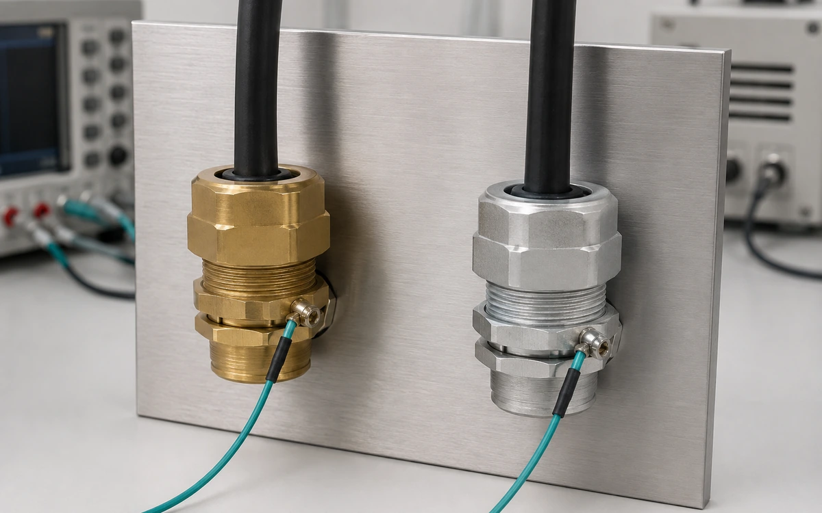
The side-by-side panel keeps mounting and sensor locations comparable while the checklist fixes cable, enclosure, heat-input and ambient conditions.
Define and record these boundaries before interpreting a temperature difference:
- exact alloy, condition, finish and part geometry;
- same cable construction, diameter, bend and termination arrangement;
- same enclosure material, wall thickness, entry location and mounting hardware;
- stated tightening method and assembly condition;
- controlled current or heat input and its measurement uncertainty;
- ambient temperature, airflow, orientation, nearby heat sources and solar load;
- sensor type, attachment, location, emissivity assumptions and sampling interval;
- steady-state criterion or defined transient sequence;
- seal, retention and ingress checks required after thermal exposure.
I use ASTM E1225 for homogeneous-specimen conductivity within its scope. Installed gland temperature, retained sealing, and joint behaviour require a complete test matching that configuration. Keep the material and product conclusions separate.
Use conditional selection rules
I consider aluminum when reduced mass matters and the alloy, finish, load capacity, and thermal result suit the duty. Higher conductivity supports investigation but does not complete selection. I consider brass when its grade, machined threads, finish, and environmental compatibility meet the requirements within the product’s temperature limits. Density or lower conductivity alone cannot establish a bottleneck. Reject either candidate if its seal, cable, corrosion pairing, thread, certification, or verified range is unsuitable. Changing metal cannot correct every limiting interface. For suspected stress or distortion, the cable-gland FEA guide covers finite element analysis. Define geometry, loads, contacts, materials, and validation before interpreting the model’s stress colours.
Conclusion
I compare brass and aluminum as complete thermal paths. Conductivity explains heat flow through the body, while alloy, geometry, interfaces, seals, cable, wall, and surroundings determine installed behaviour. Conductivity alone cannot establish ampacity, sealing, or a safe operating range.
I define the required outcome, compare assemblies under the same conditions, and verify mechanical and environmental limits across the temperature duty. Select the metal after the evidence shows which complete configuration meets those requirements.
Frequently asked questions
Does an aluminum cable gland automatically run cooler than a brass gland?
No. Aluminum alloys may have higher bulk thermal conductivity than brass alloys, but surface temperature also depends on alloy, geometry, mass, interfaces, heat source, enclosure and airflow. Only a configuration-matched calculation or test can establish which complete gland runs cooler in the intended installation.
Can changing from brass to aluminum increase cable ampacity?
Not by assumption. Cable ampacity is a system result based on cable construction, losses and installation thermal conditions. A gland substitution may change a local heat path, but any higher current rating needs a valid cable-system calculation or test covering the changed configuration.
At what temperature should I switch from aluminum to brass?
There is no universal crossover temperature. Check the exact body alloy, seal compound, cable jacket, surface treatment, mechanical loads, corrosion environment and the product’s qualified temperature or ambient range. The limiting component may not be the metal body.
Is melting point a useful cable-gland selection limit?
Usually not by itself. Seals, cables, coatings, thread strength, contact pressure or certification conditions can become limiting far below the body’s melting point. Use the complete product’s verified range and the installed configuration rather than a bulk-metal melting value.
Sources and technical references
- ASTM E1225-25a, Standard Test Method for Thermal Conductivity of Solids Using the Guarded-Comparative-Longitudinal Heat Flow Technique, accessed 2026-09-06.
- NIST, Thermal Conductivity of Aluminum, Copper, Iron, and Tungsten for Temperatures from 1 K to the Melting Point, accessed 2026-09-06.
- ASTM E228-22, Standard Test Method for Linear Thermal Expansion of Solid Materials With a Push-Rod Dilatometer, accessed 2026-09-06.
- IEC 60287-1-1:2023, Electric cables — Calculation of the current rating — Part 1-1, accessed 2026-09-06.
- IEC 62444:2010, Cable glands for electrical installations, accessed 2026-09-06.