

For vent plug validation, use an IP test to classify enclosure ingress protection. Add application immersion testing for different liquids, pressures, temperatures or wetting cycles. I test the vent in the intended mounting and assess water entry separately from airflow. This shows whether the assembly keeps water out and whether it still performs its pressure-equalization job after the specified exposure and recovery.
Key takeaways
- An IP test provides a standard classification; a custom immersion test answers a defined service question.
- Test the vent-to-wall seal and other enclosure openings as part of the installed boundary.
- Calculate pressure at the vent and compare it with internal pressure, rather than using depth alone.
- Define exposure, recovery and acceptance limits before testing.
- Measure ingress and retained airflow separately, then investigate the path responsible for any failure.
How do IP tests fit vent plug validation?
An IP classification describes enclosure protection under the access, solid-object and water tests applicable to that code. IEC 60529, consolidated edition 2.2, provides the classification system. Use the specified method, specimen and acceptance requirements when assigning an IP result. The IEC 60529 guide explains the numerals and enclosure boundary.
An application immersion test examines the assembly under a chosen service exposure. For example, it may use salt water, repeated flooding, a thermal sequence or a defined recovery period. I choose those conditions from the expected failure mechanism: water reaching the interior, a damaged entry seal, or reduced vent flow after wetting.
| Test choice | Main question | Conditions to establish | Useful result |
|---|---|---|---|
| IEC 60529 IP test | Does the enclosure meet the selected ingress class? | The applicable standard method and equipment requirements | Classification for the tested configuration |
| Custom water immersion | Does the assembly withstand the specified wet cycle? | Liquid, depth or pressure, temperature, time and operating state | Ingress and functional response under that cycle |
| Immersion followed by airflow measurement | Does useful venting return after exposure? | Baseline flow method, wet exposure, recovery and repeat measurement | Flow retained or recovered at the defined pressure difference |
| Immersion after environmental conditioning | Does prior exposure change sealing or function? | Relevant temperature, mechanical or other conditioning before immersion | Effect of the chosen sequence on the assembly |
The routes can be combined. Keep an IP test when the product requires that classification, then add the service exposure that matters to the application. Report a custom test under its own method name unless it also satisfies every requirement of the applicable classification method.
IEC 60068-2-18:2017 provides water-test methods covering drops, impacting water, immersion and high-pressure water impact. Its purpose includes checking equipment function after, and where necessary during, exposure. Use corrosion methods separately when corrosion is the question. A longer immersion is useful only when its liquid, pressure and sequence represent the mechanism being investigated.
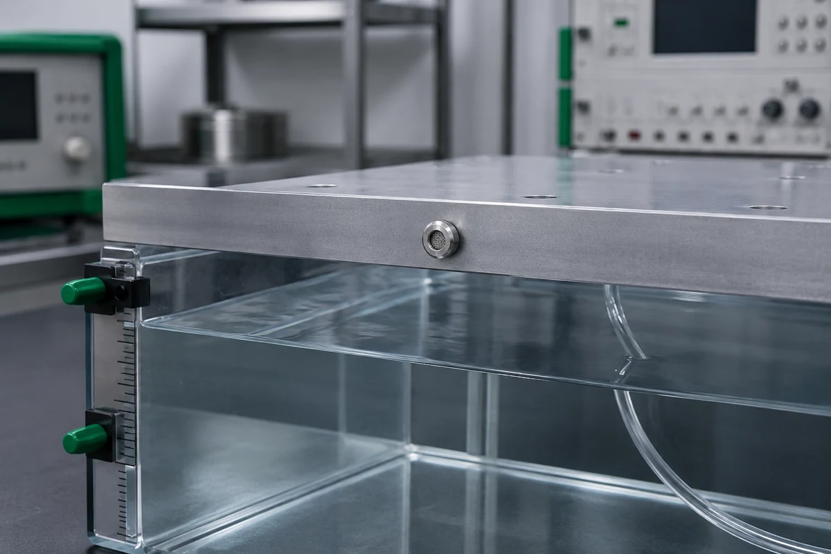
Build the installed boundary before setting the water level
The test boundary is the complete surface separating the protected interior from the environment. On a vented enclosure it includes the vent membrane or element, vent-to-wall seal, lid seam, cable entries, blanking devices and any drains. I mark these paths on the specimen drawing so that later observations can be tied to a location.
A vent mounted in a test panel is useful for studying that mounting. For an enclosure ingress requirement, use the intended enclosure arrangement, including its wall thickness, seating face, seal, orientation and closure method. Support attached cables as they will be supported in service. Deal with cable ends and auxiliary openings deliberately, since they can create an additional water path.

Before filling the tank, establish four groups of inputs:
- Assembly: vent part, mounting hole or thread, seal and accessories, wall, cover and other penetrations.
- Exposure: liquid composition, temperature, level or pressure, ramp, dwell, flow or stagnation, and number of cycles.
- Operating state: whether the equipment runs during immersion, the internal pressure condition, and any temperature changes.
- Recovery and measurements: drainage, drying time, inspection sequence, airflow method and the acceptance limits for each response.
These inputs also help choose the test equipment. A static tank controls water head. A pressure vessel can impose a different pressure history. A thermal sequence needs control of both specimen and liquid conditions. Plan any energized immersion in a laboratory setup with suitable electrical protection and safe handling controls.
Calculate the pressure across the vent
Hydrostatic pressure is the pressure contribution from a stationary liquid column. NOAA’s explanation of ocean pressure describes its increase with depth. For a uniform liquid, use vertical depth measured from the liquid surface to the interface of interest.
The static pressure difference across the vent is:
Here, is pressure at the liquid surface, is internal enclosure pressure, is liquid density, is gravitational acceleration, and is vertical liquid depth. Use the same pressure reference for and . Positive means greater pressure outside the enclosure. With density in kg/m³, acceleration in m/s² and depth in metres, the result is in pascals.
Worked example: the same depth gives different pressure differences
Assume fresh water at a uniform density of 1,000 kg/m³, a vent 1.5 m below an open water surface, and . The water column adds 14,709.975 Pa, or about 14.71 kPa. These are hypothetical static conditions; use the actual fluid density and measured pressure in a test.
| Internal gauge pressure | External gauge pressure at vent | Outside-minus-inside difference |
|---|---|---|
| 0 kPa | 14.71 kPa | 14.71 kPa |
| +4 kPa | 14.71 kPa | 10.71 kPa |
| −3 kPa | 14.71 kPa | 17.71 kPa |
I use this comparison to decide which pressure states the sequence needs to cover. A depth record with no internal-pressure information can hide a changing load across the vent. Measure pressure where needed; add waves, jets or other dynamic loads through a suitable method rather than treating them as a static head.
The calculation sets a load input, not an IP class. The subsea and underwater entry guide covers further pressure-boundary considerations where depth or external pressure dominates the design.
Plan exposure and recovery as one sequence
A recovery state is the condition in which the specimen is inspected or measured after the wet exposure. An immediate wet measurement and a measurement after drainage answer different questions. I define both when equipment must resume operation soon after flooding.
- Measure the starting condition. Inspect the assembly and record baseline ingress or leak measurements and vent flow where relevant. Establish measurement resolution and uncertainty for the required decision.
- Apply the relevant conditioning. Use the specified temperature, mechanical or other preparation, with a defined order. Check assembly condition again if the method calls for it.
- Run the wet exposure. Control liquid, temperature, pressure or level, ramp, dwell and cycles. Record actual conditions and any interruption.
- Recover the specimen. Follow the planned drainage, surface-drying and waiting period. Avoid introducing water during handling or opening.
- Repeat the measurements. Compare ingress, function and flow with their separate limits. Retain the condition at which each result was measured.
IEC 60068-2-14:2023 supplies methods for specified ambient-temperature changes. Choose the profile and its place in the sequence from the application requirement. A temperature test and an immersion test run on separate specimens will answer a different question from a combined sequence on the same assembly.
For a marine test liquid, ASTM D1141-98(2021) provides a reproducible substitute-ocean-water preparation. It represents an inorganic salt solution and omits organic material, suspended matter and marine life. Use it when that controlled chemistry fits the test purpose. Add the exposure mechanisms relevant to natural seawater service, such as deposits or changing water conditions, through a defined application method.
Separate water ingress from retained airflow
Retained airflow is the post-exposure flow compared with baseline flow under the same measurement conditions. Fix the pressure difference, flow direction, temperature and recovery state before comparing results. For pressure equalization, the useful question is how the selected vent responds over the pressure range required by the enclosure.
Water entry and airflow can produce different outcomes. A specimen may meet the ingress limit but fall below its flow requirement after exposure. Alternatively, vent flow may remain acceptable while water enters at the lid seam or mounting seal. I keep those results separate so that the corrective action addresses the failing function.
Worked example: an ingress pass with an airflow failure
Suppose an application requires at least 90% of baseline flow after its specified exposure and recovery. At the same 2 kPa pressure difference and temperature, a hypothetical vent measures 120 mL/min before testing and 96 mL/min afterward. Its retained flow is 96 ÷ 120 × 100 = 80%. The required minimum is 120 × 0.90 = 108 mL/min, so the measured flow is 12 mL/min short.
Even if that specimen meets the chosen water-ingress criterion, it fails this assumed airflow requirement. Check the flow path and recovery behavior, then repeat the relevant measurement after a justified correction. The 90% limit and measurements are example inputs, not a universal vent specification.
Choose an ingress measurement that answers the equipment requirement. Visual inspection, collected water, moisture indication, mass change and electrical checks have different sensitivities and limitations. For mass measurements, control residual external water and possible material uptake before attributing every change to internal leakage.
IEC 60068-2-17:2023 covers gross and fine leak detection in sealed specimens. A vent is an intended gas path, so select a leak method that accounts for that path rather than confusing normal gas flow with a defective enclosure seal. Any temporary blanking changes the specimen and should be reserved for a separate diagnostic test.
Condensation needs its own moisture and temperature assessment. The vent-plug condensation guide explains pressure equalization and dew point alongside ingress protection.
Choose the test route that answers the application
Use Route A when the requirement is an IP classification and the tested assembly represents the intended mounting. Use Route B when that classification is required but the application adds a different liquid, pressure history, thermal sequence or recovery duty. Use Route C for a specified engineering immersion result when an IP classification is not part of the requirement.
For example, a cabinet that needs an IP classification and must recover its vent flow after a repeated flood cycle fits Route B. Keep the standard test result, then measure the installed assembly through the separate flood-and-recovery sequence. The second test adds a useful service response while preserving the meaning of the original classification.
Inspect the first opening to locate the water path
Prepare the opening method before immersion. After the specified recovery, remove external water in the prescribed way and keep it away from the protected interior. Open the enclosure in a controlled orientation. Note the first wet location before moving the lid, cable or vent, since later handling can spread water across several surfaces.

I inspect the lid seam, vent-to-wall joint, vent element, cable entry and blanking device separately. A wet patch near the vent suggests a location to investigate; it may still have arrived along a surface from another joint. Use a controlled follow-up test to isolate the path. Keep absorbent indicators, probes and any diagnostic blanking defined in the method so they do not alter the result unnoticed.
Report actual exposure conditions alongside measurements and the acceptance decision for each response. Include relevant uncertainty and deviations, especially when a value is close to its limit. If accredited testing is required, ILAC’s guidance points to accreditation-body directories and scope certificates. Check that the chosen laboratory’s scope covers the required work.
Conclusion
An IP test and an application immersion test serve complementary purposes. The first provides the required enclosure classification; the second tests a liquid, pressure history, sequence or recovery duty that matters to the installation. Testing the complete boundary helps distinguish a vent problem from leakage at another opening.
I start with the installed assembly and its pressure states, then define the exposure and recovery sequence. Measure water entry and airflow separately, using stated limits and consistent conditions. When a result fails, preserve the first observations and isolate the affected path before changing the design or repeating the test.
FAQs about vent plug immersion validation
Does an IP68 vent plug suit every continuous-immersion application?
Compare the documented IPX8 conditions and tested mounting with the intended depth or pressure, duration, liquid and temperature. Add an application test where a relevant condition differs. Include the vent-to-wall seal and the other enclosure openings when evaluating the installed boundary.
Can a custom immersion test replace an IEC 60529 classification?
Use the applicable IEC 60529 method and all classification requirements when an IP classification is required. A custom immersion test can answer a separate service question. Report its actual procedure and conditions, and combine it with the standard test when both results are needed.
Should airflow be measured immediately after immersion or after drying?
Choose the recovery state that represents the requirement. Immediate wet flow may matter when equipment must resume operation promptly; a later measurement may show recovery after drainage. Keep pressure difference, direction and temperature consistent with the baseline, and state the recovery time for each result.
Is substitute ocean water useful for marine vent testing?
Yes, when a repeatable inorganic salt solution suits the test purpose. ASTM D1141 provides that preparation. Natural seawater also contains suspended and organic matter and marine life, so choose additional exposure conditions where those mechanisms matter to the application.
Should the vent plug be tested alone or in the enclosure?
A component or panel test can isolate vent behavior or a mounting detail. Test the intended enclosure arrangement for an enclosure ingress requirement, including the vent seal, lid and other penetrations. Use a separate component test when it helps diagnose which path or function caused a failure.
Sources and technical references
- IEC 60529, consolidated edition 2.2 — Degrees of protection provided by enclosures, accessed 2026-10-28.
- IEC 60068-2-18:2017 — Test R and guidance: Water, accessed 2026-10-28.
- IEC 60068-2-14:2023 — Test N: Change of temperature, accessed 2026-10-28.
- ASTM D1141-98(2021) — Preparation of substitute ocean water, accessed 2026-10-28.
- IEC 60068-2-17:2023 — Test Q: Sealing, accessed 2026-10-28.
- ILAC — Accredited conformity assessment bodies, accessed 2026-10-28.
- NOAA Ocean Service — How pressure changes with ocean depth, accessed 2026-10-28.