

Ex p cable glands limit leakage at cable entries in a pressurized enclosure. Ex p is a protection method that uses protective gas to help exclude an explosive atmosphere. The glands do not generate or regulate that pressure. I check the exact gland, cable diameter and construction, wall interface, accessories, installation, and certification documents together. Pressure supply, sensing, alarms, and interlocks belong to the complete system.
Key takeaways
- Treat the gland as one passive interface in the complete Ex p pressure boundary.
- Check the cable seal, gland-to-entry joint, unused openings, and possible migration through the cable itself.
- Use the minimum overpressure stated for the certified equipment or system. Do not substitute a generic value or a gland catalogue claim.
- Commission the whole enclosure with every cable and closure installed, then prove the documented low-pressure response.
- Recheck the certificate, instructions, and leakage test after any cable-entry change.
How does an Ex p enclosure hold its protective-gas boundary?
An Ex p enclosure uses protective-gas pressure to keep an explosive atmosphere outside its defined boundary. The gland contributes at the cable opening; it does not make an ordinary box Ex p equipment. A metal body or tight-looking seal is also insufficient evidence of suitability.
IEC 60079-2:2014, Equipment protection by pressurized enclosure “p” covers construction and testing of pressurized electrical equipment for explosive gas or dust atmospheres. It excludes pressurized rooms and analyser houses. For those, I start with IEC 60079-13:2017 for pressurized and artificially ventilated rooms. A certified cabinet, a pressurized room, and a flameproof Ex d enclosure address different cases. The title’s term “explosion-proof” does not make Ex p a flame-containment method.
Protective-gas boundary means the surfaces and closures separating the pressurized volume from the surrounding atmosphere. It includes walls, doors, joints, cable entries, conduits, windows, drains, and closures. Every opening adds to the leakage the gas system must accommodate.
I check each installed entry against the complete equipment design and verified pressure-loss allowance. Include unused openings and removable covers. Every entry shown by the design must also match the finished enclosure.
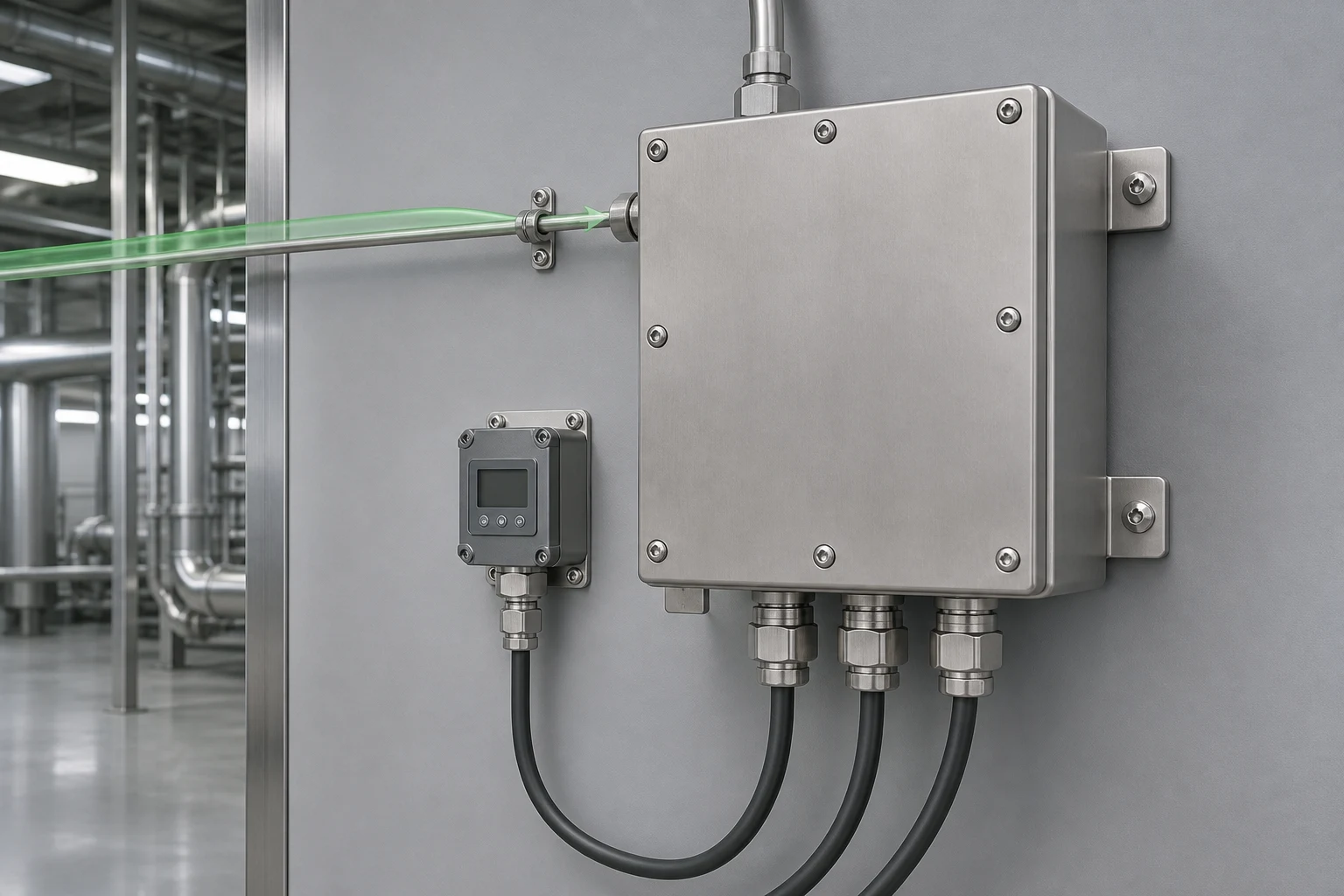
The Cable Entry Glossary explains terms such as seal, bedding, barrier, armour, and entry thread. These parts have different jobs. A cable seal limits leakage around a specified cable surface. An armour clamp terminates the cable’s armour. A barrier gland addresses a defined protection concept; its name does not make it interchangeable with either function.
Where can a cable entry leak?
Cable-entry leakage path is any route by which protective gas can leave at a cable penetration. It also includes a route by which the surrounding atmosphere can challenge the intended boundary. For example, leakage can occur between the sealing element and cable jacket, through a gland-to-enclosure interface, through a missing or unsuitable closure, or along a cable construction that permits longitudinal migration. Therefore, treat every unused opening as another boundary path and match its closure using the stopper-plug selection guide.
After work disturbs an entry, I map the actual cable or closure surface, gland-to-wall joint, and enclosure interface before testing. The cable, gland, entry geometry, accessories, and certified design determine the relevant paths. A compound barrier is not required universally for Ex p. If the design calls for one, follow the barrier-gland sealing guide and exact product instructions. Do not assume an Ex d construction applies because of its name.
| Path | Controls | Verify |
|---|---|---|
| Cable to seal | Seal range, jacket condition, roundness, and assembly | Gland size table, drawing, and instructions |
| Body to entry | Entry geometry, permitted accessories, wall condition, and engagement | Equipment and gland drawings |
| Cable interior | Construction and longitudinal migration risk | Cable datasheet and certificate schedule |
| Unused opening | Specified stopping plug or closure | Equipment documents and closure certificate |
| Disturbed entry | Movement, looseness, damage, or unauthorised replacement | Installation baseline and inspection record |
Before disturbing an entry, de-energize the protected equipment and stop the gas supply using the approved isolation procedure. Support the cable on both sides and leave the adjacent stopping plug installed. Inspect the accessible inner locking parts and gland-to-panel contact face. Place the optical probe at the visible panel interface; do not push it into the entry or loosen parts for a better view.
Compare the accessible assembly with the specified drawing before closure and leakage or functional testing. This open inspection locates accessible interfaces. Isolation, hidden thread engagement, leak tightness, and permission to return to service still require their specified checks and records.

The functional system view identifies the entry leakage path, sensing point, pressure comparison, and protective response. Use the exact gland sectional drawing and certificate schedule to locate seals, armour capture, and barrier features. The single- and double-compression gland comparison explains why seal count, armour termination, and barrier terminology must be checked from an exact sectional drawing rather than assumed from a product name.
Ex p cable glands within the certified system boundary
I begin with the certified equipment documents. Identify the protection concept, marking, equipment protection level, certificate number and issue, and ambient range. The equipment protection level indicates the protection level required for the intended hazardous setting. Check cable-entry restrictions and special conditions of use too.
Then match the actual cable construction and measured diameters to a permitted gland size. Verify the entry hole or thread, wall thickness, washers, locknut, and adaptor. Include any earth-continuity requirements and the installation instructions.
IEC 60079-14:2024 covers Ex electrical-system design, equipment selection, installation, initial inspection, documentation, and personnel competency. I use it with the equipment certificate and local rules. Each component needs a documented role in the installation. The hazardous-area cable-gland selection guide links the protection concept and cable construction to entry type, certificate schedule, marking, and installation conditions.
Check these technical boundaries together:
-
System and equipment documents: define Ex p type, permitted internal release, protective gas, required purge or dilution, minimum overpressure, monitoring, and protective action.
-
Cable datasheet: defines construction, conductor or core arrangement, bedding, armour where present, jacket material, and dimensional tolerances.
-
Gland certificate and schedule: identify the exact family, protection concept, marking, cable restrictions, seal ranges, ambient limits, accessories, and special conditions.
-
Drawings and instructions: show the actual sealing surface, preparation length, entry engagement, assembly order, and model-specific tightening method.
-
Installed configuration: links the cable, gland, closure, enclosure, and completed system test to the applicable part numbers and certificate issues.
I verify the certificate behind an “Ex certified” label. The IECEx equipment-scheme FAQ identifies the online certificate as the master controlled version and shows whether it is current, suspended, or cancelled. Its number, issue, schedule, marking, and conditions must match the installed model.
For EU placement, the European Commission’s ATEX overview describes Directive 2014/34/EU. It covers equipment and protective systems, with essential health and safety requirements and conformity-assessment procedures. Neither framework makes every certified gland suitable for every Ex p enclosure.
Commissioning the complete enclosure
Commissioning must verify the complete installed Ex p equipment. Before applying power, check every planned cable entry and the specified closure for each unused opening. Secure the doors and covers, and check the protective-gas route. If purging is required, follow the documented sequence and completion criteria. Purging replaces the enclosure atmosphere with protective gas before the allowed operating state. Then establish the required pressure and verify the permitted pressure and flow conditions.
The final cable entries, glands, accessories and closures define the tested pressure boundary. Commissioning measures the purge conditions, normal pressure, low-pressure threshold and actual protective response with the specified instruments and method. The equipment or system documents supply the acceptance limits; there is no universal gland leak-rate limit.
If pressure falls during testing, locate the cause before tightening parts. Check the cable seal, entry joint, closure, door, instrument tube, and other boundary interfaces. Check the supply and sensing lines as well. A falling pressure trend is a system symptom; it does not identify the gland as the cause.
I work from the whole pressure boundary toward individual entries. Confirm the gas supply, sensing line, doors, covers, drains, and unused openings. Then follow the enclosure’s test method to compare one entry at a time. If isolating an entry by that procedure restores pressure, inspect its cable seal and wall joint. Restore the specified parts and repeat the complete system check. Keep each pressure reading linked to the known test arrangement.
What should happen below the minimum overpressure?
Minimum overpressure is the lowest pressure difference permitted by the certified design for a defined operating state. A low-pressure condition may trigger an alarm, prevent energization, de-energize protected equipment, or invoke another specified action. The gland neither sets the threshold nor performs the response.
I verify the complete cause-and-effect chain with the documented procedure. Reduce pressure as instructed, confirm detection at the sensing point, and check the alarm or interlock output and equipment state. An interlock controls whether operation is allowed. Use the documented setpoint, delay, reset logic, and protective action. Repeat only as permitted; values from an unrelated enclosure do not apply.
The low-pressure check uses the protected equipment offline, with the gas supply and independent sensing lines connected to their designated ports. The relay signal reaches the test interface and cables remain supported. Any bleed branch must have its isolation state verified by the specified method before operation. The equipment’s cause-and-effect procedure defines the pressure change, threshold, delay, alarm or interlock and reset to test.

I use the instrument readings and event record to check the sensing and protective response against the acceptance limits. The physical layout alone cannot establish a threshold or prove an alarm, trip, purge, or permission to energize.
For equipment placed on the EU market, ATEX product obligations and conformity assessment apply before placement. In contrast, workplace controls remain a separate employer responsibility under the ATEX workplace framework described by the European Commission. That distinction matters because a compliant component certificate does not prove that a site’s area classification, pressurization logic, installation, and operating procedures are correct.
How do maintenance and cable changes affect pressurization?
A cable-entry change can affect leakage, mechanical stability, and certification coverage. A smaller replacement cable may fall outside the seal range. A different jacket may respond differently to compression or chemicals. A damaged reused seal may create a new leak path. Changing an adaptor or washer may alter thread engagement or the wall joint. Recheck the affected seal, entry and certification conditions before substituting a cable, gland, reducer, stopping plug or accessory.
IEC 60079-17:2023 covers inspection and maintenance of hazardous-area electrical installations. I use its scope with the equipment instructions and site maintenance strategy. Check for loose parts, damage, corrosion, cable movement, and seal deterioration. Look for unauthorized substitutions or incomplete closures, and reconcile the installation with its records and labels.
I set inspection and test intervals from the applicable standard, certificate, instructions, and site risk assessment. Duty, environment, maintenance history, and local rules also matter. A generic monthly, quarterly, or annual gland interval is not a substitute. After work disturbs the pressure boundary, complete the required inspection and functional checks before returning equipment to service.
Conclusion
An Ex p cable gland is a passive part of the protective-gas boundary. It can limit leakage at the cable seal and enclosure entry when the exact gland, cable, accessories, interface, and installation match the certified design. Pressure generation, minimum-overpressure supervision, and the documented low-pressure response remain system functions.
I assess the cable entry within the complete Ex p system. Verify the final enclosure, cables, closures, doors, gas route, sensing point, and protective actions together. The purge or pressurization sequence, allowed leakage, operating pressure, and low-pressure response must all satisfy the documented design. The completed system test supplies that evidence; a gland label or isolated bench check cannot establish the whole result.
FAQs about Ex p cable entries
Does an Ex p cable gland actively maintain enclosure pressure?
No. The gland is a passive part of the pressure boundary. It can limit leakage at the cable and enclosure entry when the exact parts are correctly selected and installed. The protective-gas supply creates the pressure, while system sensing and control equipment supervise the minimum overpressure and apply the documented response.
Is a barrier gland always required for an Ex p enclosure?
No universal rule makes every Ex p cable entry a barrier gland. The required construction depends on the equipment certificate, cable construction, entry arrangement, internal release scenario, installation standard, and local rules. Do not substitute an Ex d barrier-gland rule or a generic compound-seal claim for the exact Ex p equipment documentation.
What pressure should an Ex p cable gland be rated for?
Start with the pressure and test conditions stated for the certified enclosure or system, not a generic gland value. Confirm that the selected gland and complete entry arrangement are permitted for those conditions. The minimum operating overpressure, maximum abnormal pressure, purge conditions, and acceptance test can answer different questions and should not be collapsed into one number.
Should the gland be leak-tested separately or with the enclosure?
Product testing can support the gland’s certificate, but commissioning must verify the complete installed pressure boundary. Test the enclosure with its cables, entries, closures, doors, tubing, and monitoring system in their final arrangement. Use the procedure and acceptance criteria named by the equipment or project documents, then record the result and low-pressure response.
Sources and technical references
- IEC 60079-2:2014, Equipment protection by pressurized enclosure “p”, accessed 2026-09-07.
- IEC 60079-13:2017, Equipment protection by pressurized room “p” and artificially ventilated room “v”, accessed 2026-09-07.
- IEC 60079-14:2024, Electrical installation design, selection and installation of equipment, including initial inspection, accessed 2026-09-07.
- IEC 60079-17:2023, Electrical installations inspection and maintenance, accessed 2026-09-07.
- IECEx, FAQs for the Certified Equipment Scheme, accessed 2026-09-07.
- European Commission, Equipment for potentially explosive atmospheres (ATEX), accessed 2026-09-07.