

Cable gland clamping range is the cable-diameter interval that a specified gland configuration is designed to accept at a named seal or grip. It helps you choose a gland that closes correctly around the cable. I compare the cable’s full outside-diameter range with the exact gland range, then check the other cable layers and enclosure entry.
A cable that is too small may leave the seal or grip short of its intended contact. A cable that is too large may be difficult to insert or overload the seal when the cap closes. Correct selection starts with the actual cable construction and its tolerances, followed by the installation method for that gland.
Key takeaways
- Identify the cable surface and function covered by each range in the product table.
- Compare minimum and maximum cable OD, including production tolerance, with both gland limits.
- Use perpendicular measurements to retain ovality information, and measure at the intended sealing location.
- Calculate lower and upper margins; a negative value identifies the end that falls outside the range.
- Match armoured-cable layers, enclosure entry, seals and installation instructions before fitting the selected gland.
Which part of the cable does the range describe?
A sealing range is the diameter interval accepted by the seal at its specified cable surface. A clamping range may describe that same interface or a separate gripping feature, depending on the product. I read the table heading, drawing and notes together to identify the part being sized.
A simple unarmoured gland may list one finished cable outside-diameter (OD) range. An armoured design can list outer-sheath, bedding and armour dimensions separately. Some families also offer different inserts within one body size. Keep the insert and accessory choice with the selected order code.
Why the seal design sets the usable range
In a compression-seal design, closing the cap deforms the elastomer around the cable. The seal must reach the jacket around its circumference while remaining supported by the surrounding parts. A smaller cable requires more inward movement to establish that contact; the available movement depends on the seal profile and gland geometry. A larger cable leaves less space for the seal and can make insertion or closure difficult. This is why the relaxed bore of a loose insert differs from the usable cable range of the assembled gland. I select the specified insert and closure arrangement together. Changing an insert’s thickness or profile can change the accepted cable interval even when the body’s entry thread stays the same. Correct sizing gives the intended contact without relying on extra cap force to compensate for a mismatch.
IEC 62444:2010 addresses complete cable glands as supplied by the manufacturer or supplier. This is the useful selection unit: the body, seal and other supplied parts work together. A loose insert measurement is not a substitute for the complete assembly’s stated cable range.
| Product-table field | Surface or connection being sized | Dimension to compare |
|---|---|---|
| Cable sealing range | Seal against the finished jacket | Minimum and maximum finished OD at the seal |
| Separate retention range | Grip or strain-relief feature | Cable size and construction specified for that feature |
| Outer-sheath range | Outer seal on an armoured cable | Finished outer jacket diameter |
| Bedding or inner-sheath range | Inner seal after cable preparation | Diameter of the named prepared layer |
| Armour range | Metal armour clamp or termination | The stated wire, braid, tape or strip dimension |
| Entry thread or mounting hole | Gland body at the enclosure | Full thread designation or hole and panel dimensions |
If a table uses “clamping range” without identifying the interface, check its assembly drawing before selecting. This avoids comparing a finished outer diameter with a range intended for bedding or armour. The gland size-chart guide explains the wider product-table layout.
Measure the cable where the gland will seal
The cable OD interval is the span from the smallest to the largest finished diameter allowed for the cable being installed. Start with the cable maker’s dimensions and tolerances. Measurements then help check the delivered cable and local shape at the sealing position.
I measure a sound section of the correct jacket, with the jaws square to the cable. Excess force can compress a soft sheath and understate its diameter. Keep the cable’s condition and temperature consistent with the dimensional basis being used, especially when a reading is close to a limit.
- Identify the exact cable construction and the layer that will touch the seal.
- Check the cable maker’s minimum and maximum dimensions, including any stated conditions.
- Measure at the planned seal location with a suitable instrument and controlled contact force.
- Take perpendicular readings where the cable may be oval; retain both values.
- Record ribs, wraps, printing, damage or surface features that affect contact.
- Compare local findings with the specified cable interval and the gland’s permitted profile.
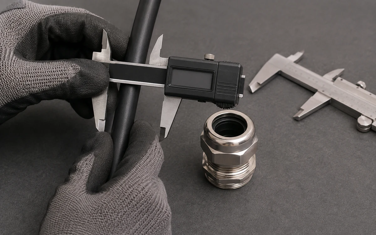
Ovality is departure from a circular cross-section, shown by unequal diameters in different directions. A seal designed for a round cable must accommodate the actual profile as well as its size. Averaging a large and small reading can hide the dimension that creates a gap or excessive squeeze.
For a flat or oblong cable, use the specified width, thickness, corner shape and orientation. The flat-cable gland guide explains the matching seal geometry. A diameter calculated from equal area does not recreate that outline.
Compare both ends of the cable and gland intervals
A suitable dimensional pairing contains the whole cable interval within the gland’s applicable range. I check the lower end for adequate closure around the smallest cable and the upper end for fit around the largest. Partial overlap leaves some allowed cable sizes outside the selected range.
Use the same units and the same physical surface for both intervals. A millimetre value for bedding cannot be compared with the outer-jacket range, even when the numbers happen to overlap.
Calculate the lower and upper margins
Dimensional margin is the distance between a cable interval limit and the corresponding gland limit. Let and be the cable limits, and and the gland limits, all in millimetres. The two margins are:
Positive values mean the entered cable limits lie inside the gland range. A negative value shows which cable limit falls outside. Zero means the cable and gland limits coincide, so apply the product’s endpoint convention and the relevant measurement decision rule.
A worked comparison with one cable interval
For example, suppose a hypothetical cable has a permitted OD of 9.8–10.3 mm. The three gland ranges below are illustrative configurations, not product ratings. Applying both margins exposes the difference between full coverage and a range that accepts only part of the cable population.
| Hypothetical gland range | Lower margin | Upper margin | Dimensional decision |
|---|---|---|---|
| 8.0–12.0 mm | 1.8 mm | 1.7 mm | Both cable limits lie inside; continue the profile and installation checks |
| 8.0–10.0 mm | 1.8 mm | −0.3 mm | The largest permitted cable exceeds the upper limit; select a suitable configuration |
| 9.8–12.0 mm | 0.0 mm | 1.7 mm | The lower limits coincide; confirm the endpoint and uncertainty rule |
The middle row shows why choosing from nominal OD alone can fail. A 10.0 mm nominal cable appears to meet a 10.0 mm upper limit, but its allowed 10.3 mm maximum does not. Extra tightening does not change the declared range. Use a suitable insert or gland configuration permitted by the product instructions.
Match each layer of an armoured cable
An armoured gland can act on several surfaces at different axial positions. I identify the outer seal, any inner seal and the armour clamp on the assembly drawing, then map each one to its cable layer. The finished overall OD supplies only the outer-layer dimension.

Bedding is the layer beneath the armour that supports and separates it from the inner cable construction. A design with an inner seal may specify this prepared diameter or an inner-sheath diameter. Use the exact named layer and preparation length so the seal lands on the intended surface.
The armour table may specify wire size, braid or tape thickness, or another construction-specific dimension. Preserve that column’s name and unit when comparing the cable. A gland without an inner seal does not need a bedding-seal check merely because another product family has one.
Retention may also use a different feature from the environmental seal. The sealing and strain-relief comparison explains the two load paths. Match the cable construction and required retention duty to the selected assembly as well as checking its sealing dimensions.
Check enclosure fit independently
The entry thread is the gland body’s threaded connection to the enclosure or locknut. Its nominal size does not identify the cable diameter. One metric entry size may be sold with several cable ranges, and two different entry sizes may accept the same cable OD.
For a tapped hole, compare the complete thread designation, pitch, form and usable engagement. Check the specified wall-sealing arrangement and available internal space. For a clearance hole, compare hole tolerance, panel thickness, locknut, washer and any anti-rotation feature.
The M16 gland guide separates entry size from cable size. The PG, metric and NPT comparison helps identify the thread system. Resolve both the cable-facing fit and the enclosure-facing fit before installation.
What should you do at a range boundary?
A boundary case occurs when a cable limit equals a gland limit, or the measured value is too close to distinguish confidently from it. Check whether the product’s stated range includes the endpoint and whether the catalogue value is rounded. Then apply the measurement rule used for acceptance.
NIST defines a decision rule in terms of how measurement uncertainty is considered when stating conformity. The BIPM’s JCGM guides include guidance on uncertainty and conformity assessment. At a cable entry, instrument uncertainty, repeatability, contact force and cable condition can all matter near the limit.
Measurement resolution is the ability to distinguish small changes in the measured diameter. NIST’s resolution guidance explains why the number of displayed digits does not establish that ability. I keep resolution, production tolerance and measurement uncertainty separate. Production tolerance describes the cable dimensions that may be supplied; uncertainty describes how well a measured dimension is known. Check instrument calibration, repeatability, measuring force and the measurement procedure when deciding whether a small indicated margin is useful. A reading with two decimal places can still have uncertainty greater than the displayed step.
Boundary example: a positive reading margin can miss the acceptance rule
Suppose a hypothetical inspection gives a cable diameter of 9.97 mm with an expanded measurement uncertainty of 0.05 mm. Assume the purchaser and supplier have agreed, for this upper-limit check, to accept only when the measured value plus that uncertainty is no greater than the gland limit. This is the chosen rule for the example, not a universal gland requirement. Both candidate configurations are assumed to satisfy the lower-limit and profile checks.
| Hypothetical upper limit | Margin using the reading alone | Reading plus uncertainty | Result under the agreed rule |
|---|---|---|---|
| 10.00 mm | 0.03 mm | 10.02 mm | Exceeds the acceptance boundary by 0.02 mm |
| 10.50 mm | 0.53 mm | 10.02 mm | Leaves 0.48 mm within the acceptance boundary |
In this calculation, I found that the first configuration has a positive 0.03 mm reading margin yet misses the agreed acceptance rule. The second configuration has room for this measurement uncertainty at its upper limit. For the first, resolve acceptance using an appropriate measurement method or select a compatible configuration with more allowance. Do not round 10.02 mm down to make the result fit. This inspection concerns one measured cable position; the full production interval, lower boundary and remaining sealing, retention and entry checks still belong in the selection.
Install the selected range as a complete assembly
Once the dimensions fit, assemble the identified body, seal, insert and accessories around the specified cable. Use the correct preparation, closure or torque instructions for each joint. Keep the jacket sound at the seal and route the cable so bending or weight does not disturb the entry.

Check that the cable and wall seals are both seated, and that the body, locknut and cable support serve their intended functions. IEC 60529 classifies enclosure protection degrees. Maintaining the required ingress protection depends on the assembled cable entry and enclosure interfaces, with the conditions specified for them.
I also check the service temperature, chemicals and cable movement against the selected parts. A dimensionally suitable seal can still be the wrong compound for the environment. These checks turn a size match into a suitable installation without changing the meaning of the range itself.
Conclusion
Cable gland clamping range helps select the cable-facing seal or grip when its interface is clearly identified. I compare the full cable interval with both gland limits, use the two margins to locate any mismatch, and keep the cable’s actual profile in view. For armoured cable, each seal and armour feature needs its own layer dimensions.
Finish by matching the enclosure entry and assembling the exact permitted parts. At a boundary, resolve endpoint and measurement rules before fitting the gland. This sequence prevents a nominal cable diameter or familiar thread size from hiding an unsuitable pairing.
Frequently asked questions
Is cable gland clamping range the same as the entry thread size?
Clamping or sealing range sizes a cable-facing interface; entry thread sizes the connection to the enclosure. Check both values independently. One thread size may have several seal ranges, while glands with different entry threads may accept overlapping cable sizes.
Can a cable exactly at the minimum or maximum clamping value be used?
Use the product’s stated endpoint convention and the applicable measurement decision rule. Confirm the surface, cable condition and whether the value is rounded. A clearly included endpoint may be usable within those conditions; unresolved uncertainty or an unclear range calls for further clarification before assembly.
Which diameter should be checked for an armoured cable gland?
Map each gland feature to the corresponding cable layer. These may include finished outer-jacket OD, prepared bedding or inner-sheath diameter and a separately specified armour dimension. Use only the interfaces present in the selected design, and keep their column names and units distinct.
Does a cable inside the clamping range prove sealing and strain relief?
It establishes the dimensional match for the named range. The selected cable profile, jacket, seal, grip and assembly method must also suit the required sealing and retention duties. Check the complete gland’s applicable performance and enclosure-entry conditions before installation.
Sources and technical references
- IEC 62444:2010, Cable glands for electrical installations - IEC, edition 1.0, accessed 2026-10-29.
- JCGM Publications: Guides in Metrology - BIPM, accessed 2026-10-29.
- Decision Rule - National Institute of Standards and Technology, accessed 2026-10-29.
- NIST — Measurement-system resolution, accessed 2026-10-29.
- IEC 60529:1989+A1:1999+A2:2013, Degrees of protection provided by enclosures (IP Code) - IEC, consolidated edition 2.2, accessed 2026-10-29.