

Use IP protection ratings to match a cable entry to its dust and water exposure, then select the gland and seals that fit the actual cable and enclosure. I identify the required protection level first, including any jet or immersion duty. Next, I check the cable-facing seal and the gland-to-wall joint, because both form part of the enclosure’s protective boundary.
A useful selection combines the right classification with a workable assembly. The cable range, wall seal, accessories and fitting method matter as much as the code on the product sheet. Plan those details before fixing the entry size or substituting a gland.
Key takeaways
- Read the access/solids and water positions of the IP code separately.
- Match the water mechanism: drops, spray, jets and immersion are distinct conditions.
- Compare an IPX8 entry with its stated immersion conditions.
- Keep the cable seal and wall joint compatible with the selected arrangement.
- Choose materials, support and any electrical or Ex functions for the same service.
Read IP protection ratings as two separate requirements
An IP code classifies enclosure protection against access to hazardous parts, solid foreign objects and harmful water ingress. IEC 60529 defines the classification and tests. After the letters IP, the first numeral addresses access and solids; the second addresses water. Read the complete designation in the equipment specification, including any additional letters.
The IEC’s ingress-protection overview in Smart lighting explains the two digit positions and the range from falling water to immersion and jets. The same code structure lets you identify which environmental challenge the equipment has been assessed against.
X in an IP designation leaves that numeral unspecified. For example, IPX8 gives a water classification with no first-numeral claim. Appendix A of the US Department of Homeland Security’s ingress-protection reference tables explains this notation and the different dust and water levels.
Three common examples help when reading gland data:
| Code | Solids position | Water position |
|---|---|---|
| IP65 | Dust-tight | Water jets |
| IP66 | Dust-tight | Powerful water jets |
| IP68 | Dust-tight | Continuous immersion under the stated equipment conditions |
Read the water descriptions as test conditions, then compare them with the service. For a location exposed to both washing jets and flooding, check that the selected entry covers both. The IP rating chart gives the wider numeral-by-numeral explanation.
Describe what can reach the enclosure
The protected boundary is the enclosure surface separating the equipment from its surroundings. Include the cable gland, wall joint, doors, seams, plugs, vents and other openings. I trace likely paths for water and dust around that whole boundary, then look closely at the cable entry’s location and orientation.
Describe normal operation, cleaning and foreseeable accumulation of water. An entry under a canopy may face wind-driven spray, while an entry near a floor drain may also face a rising water level. Include the state of doors and covers during the exposure, and use the governing equipment or project requirements to set the necessary designation.
| Exposure detail | Why it changes the selection |
|---|---|
| Dust or objects at the boundary | Sets the required solids and access protection |
| Spray or cleaning jets | Determines the water mechanism and directions to address |
| Pooling or immersion | Requires the water level, duration and equipment state to be defined |
| Hot cleaning water or added chemicals | Adds temperature and material-compatibility duties |
| Cable movement, weight or vibration | Changes the support and retention needed to preserve sealing |
| Entry orientation and nearby surfaces | Affects run-off, retained water and access for assembly |
For example, a cabinet may receive routine hose cleaning while a low entry can become submerged during a drain blockage. I treat those as two exposure cases. A suitable gland must fit the cable and wall in each case, and the surrounding enclosure needs the same review.
The deluge and flooding guide helps assess rising water, drainage and recovery. Record the resulting requirement in physical terms so that a gland’s stated conditions can be compared with the actual installation.
Match the cable seal and wall joint
The cable seal is the element that closes the path between the cable jacket and gland body. It contacts the cable’s permitted outer layer. Match the exact insert to the full outside-diameter (OD) tolerance, profile and jacket material. A cable at the edge of a range needs its real dimensions checked; conductor area alone does not describe the surface being sealed.
I also locate the permitted contact section. Ribs, corrugations, damage, a breakout or an abrupt diameter transition can change how the seal meets the cable. Select a gland made for that construction and follow its preparation length and tightening method. Provide support so weight and movement do not distort the entry.
The wall joint is the connection between the gland body and enclosure entry. Its seal closes the path around the outside of the gland. It may use a face washer, O-ring or a specified thread-sealing arrangement. Check the opening or female thread, panel thickness, flat seating land, coating and rear hardware. Keep the required engagement while giving the seal its intended contact and compression.
IEC 62444:2010 covers construction and performance of complete glands as supplied. It directly covers IEC 60423 metric entry threads and can guide assessment of other types. Use the gland’s declared mounting arrangement to connect those component properties to the actual enclosure entry.
| Interface | Selection check | Typical correction |
|---|---|---|
| Cable to insert | Cable dimensions, shape, jacket and contact land | Select the appropriate insert or gland size |
| Gland to wall | Thread or hole, flatness, panel thickness and seal | Correct the opening or choose the permitted wall-seal arrangement |
| Gland to adaptor | Both thread forms, engagement and seal locations | Use an approved matching adaptor and its specified seals |
| Unused opening | Plug, thread or hole, seating and retention | Fit the specified stopping component |
| Cable route | First support, bend and movement | Reposition support or entry to keep the seal stable |
For a nominal M20 entry, confirm the pitch and full mounting geometry before fitting the part. The M20 specification guide explains those details. If an adaptor is added, include its extra joint in the sealing arrangement.
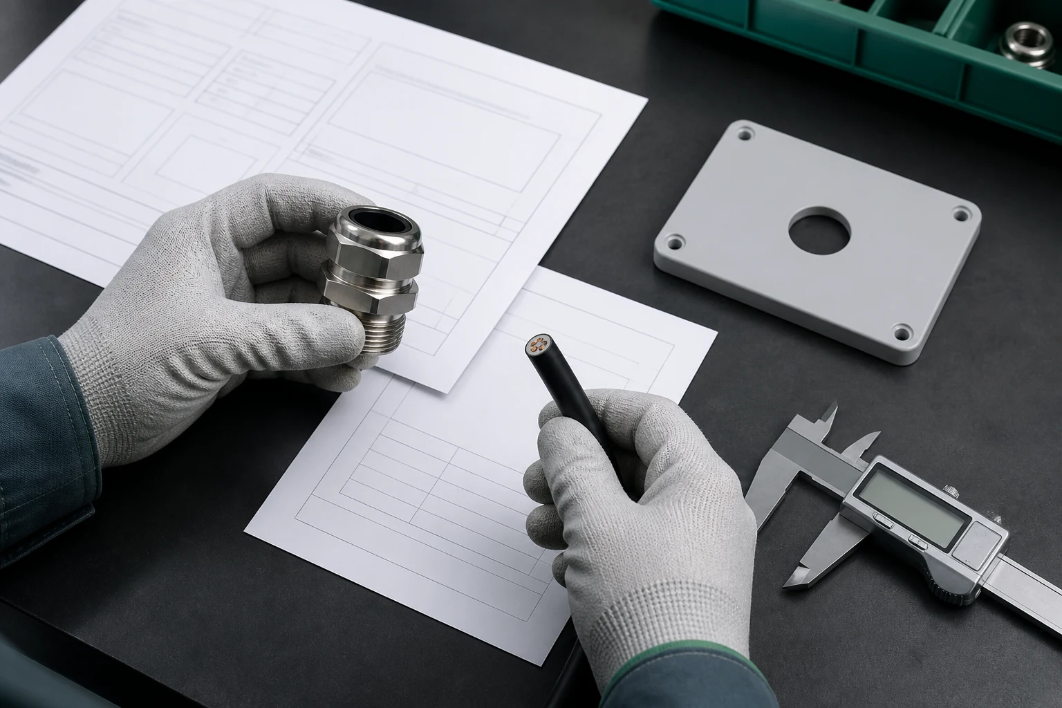
Gloved hands hold the gland and cable beside an entry plate, caliper and component drawings.
Compare immersion and cleaning duties explicitly
An immersion condition describes how the assembly is exposed below water, including the level or pressure, duration and operating state. For an IPX8 selection, obtain the conditions stated for the equipment and compare them with the required duty. Include the actual gland, cable, entry seals and orientation used in that assessment.
For example, two glands can both be marked IP68 yet have different stated immersion conditions and cable ranges. I compare the required water exposure first, then check which gland fits the proposed cable and wall. That identifies the usable option without treating the shared code as a complete specification.
Where jets and immersion both occur, select an entry documented for both required water conditions. A cleaning jet loads the entry differently from standing water. Also compare nozzle direction, temperature and cleaning compounds with the permitted service; those details can influence the seal material and installation layout.
Keep condensation in the enclosure moisture assessment. Water already present inside, or moisture that condenses there as temperatures change, needs suitable moisture control. Review the cable route and other openings before changing the gland simply because droplets appear inside the box.
Choose materials and support for the same environment
Material compatibility means the body, seals and accessories retain the functions needed in the exposure. Review the temperature range, sunlight, oils, cleaners, salt and corrosion conditions for each part. The cable jacket and wall coating are part of that review because they form the surfaces against which the entry is assembled.
The cable-gland material guide compares those material choices. I select the body and sealing compound together, then check any locknut, adaptor or washer. A suitable metal body still needs an elastomer and cable jacket compatible with the cleaning chemistry and temperature.
Cable retention controls movement of the cable relative to the gland. Match the required retention and external support to cable weight, pulling, vibration and bending. Keep repeated motion in the part of the route designed for it so the cable remains stable where the seal contacts it.
Protective bonding, electromagnetic compatibility (EMC), fire requirements and hazardous-area (Ex) protection also have their own functions. Where explosive atmospheres are present, follow the applicable certificate and installation conditions for the complete entry. The mining and tunneling selection guide shows how ingress, cable construction and Ex requirements interact in those applications.
Select the complete entry and preserve it during installation
I compare the exact proposed assembly with the gland’s rating information and fitting instructions. The useful details are the model and insert, cable range, wall mounting, seals, accessories and relevant exposure conditions. Resolve any difference that changes seal contact or the assessed arrangement before treating the part as a suitable choice.
When the project requires accredited testing, verify the laboratory’s status and relevant scope through its accreditation body. ILAC’s guidance explains where those records are held. Use the report to check the specimen and test conditions against the proposed entry, keeping that review focused on the actual selection.
Carry the selected parts into the installation without swapping the insert, washer or adaptor for a similar-looking item. Prepare the cable and opening as instructed, protect the seal lands, use the stated tightening setting and support the cable. The IP68 installation guide follows these steps through to the completed entry.
After fitting, inspect the cable seal, wall seal and all unused openings. Look for a folded washer, damaged jacket, tilted shoulder, loose hardware or cable side load. Complete any required enclosure test with the specified method and safe equipment state. Record the installed parts so maintenance can preserve the arrangement.
Recheck the affected interfaces after replacing a cable, adding an adaptor or moving an entry. If the installation leaks, trace the water path before retightening the cap: the cable seal, wall joint and other openings need different corrections. Restore the right parts and assembly method, then repeat the relevant checks.
Conclusion
IP protection ratings help define the access, solids and water duties of a cable entry. Start with the exposure and governing requirement, then match the gland to the cable-facing seal, wall joint and any additional openings or accessories. For immersion, compare the stated conditions with the installation’s water level and duration.
I select the complete entry together with its materials, support and required electrical functions. During fitting, preserve the seal locations and tightening method that belong to that selection. After installation or later changes, inspect the affected joints and complete the required verification so the intended enclosure protection is maintained.
FAQs about IEC 60529 cable gland selection
Does a higher IP number always mean a better cable gland?
Choose the code that addresses the required access, solids and water conditions, then match the cable and enclosure interfaces. A gland suited to immersion may have different declared conditions from one selected for cleaning jets. Check both duties where both occur, together with materials and support.
How do I choose an IP68 gland for immersion?
Compare its stated immersion conditions with the required water level or pressure, duration, orientation and operating state. Then match the exact gland, cable range, wall seal and accessories. Keep the chosen installation method with the selected parts.
How does the gland contribute to the enclosure’s IP rating?
It closes the cable entry through the cable-facing seal and the gland-to-wall joint. Both must fit the installed cable and mounting arrangement. Doors, seams, plugs, vents and other openings also form part of the enclosure boundary assessed for ingress protection.
What should I check for chemicals, sunlight and heat?
Review the body, seal compound, accessories, cable jacket and enclosure finish for those exposures. Use their stated temperature and compatibility limits, and include cleaning materials used during maintenance. Choose the support and route so movement does not disturb the seals.
What should I do when the cable or wall arrangement changes?
Recheck cable dimensions and jacket contact, wall-seal seating, thread engagement, accessories and support. Compare the revised assembly with the gland’s permitted arrangement, then repeat the affected installation and enclosure checks. Keep the updated part details with the equipment record.
Sources and technical references
- IEC 60529, Degrees of protection provided by enclosures: consolidated edition 2.2, accessed 2026-10-28.
- IEC, Smart lighting: ingress-protection overview, accessed 2026-10-28.
- US Department of Homeland Security, Enhanced Responder PPE Transport Bags: Appendix A, Ingress Protection Levels, accessed 2026-10-28.
- IEC 62444:2010, Cable glands for electrical installations, accessed 2026-10-28.
- ILAC, Accredited Conformity Assessment Bodies, accessed 2026-10-28.