

Flat cable glands use a shaped cable seal to fit a flattened or other specified non-circular cable profile. I choose one when a flat cable needs to cross an enclosure wall while keeping its intended orientation, seal and mechanical support. The starting dimensions are width and thickness, followed by the edges, corners and jacket surface that the seal will contact.
A round outer body can contain a flat insert. A flanged entry can use an oblong opening. What matters is how the cable-facing parts match the actual cross-section and how the body mounts to the enclosure. I check those two interfaces separately, then add the required retention, electrical functions and environmental duty.
Key takeaways
- Select from the complete cable outline: width, thickness, corners, grooves and jacket condition.
- Include the permitted variation in both dimensions; nominal width alone can hide a thickness mismatch.
- Use equal-area diameter for a geometry comparison, while retaining the real outline for gland selection.
- Match the wall opening, entry seal, mounting stack and tool access independently of cable fit.
- Keep cable support and bend orientation aligned with the gland and termination.
What is a flat cable gland?
A flat cable gland is a cable-entry assembly with a sealing or gripping arrangement designed for a specified flattened profile. It commonly brings together a body, shaped seal, closing parts and an enclosure mounting interface. The internal construction determines where compression acts and which parts hold the cable against movement.
IEC 62444:2010 addresses complete cable glands as supplied. When comparing flat variants, I therefore identify the body, insert and accessories together. A different insert may change the accepted cable dimensions even when the external body and entry thread remain the same.
A flat multi-conductor cable is still one cable when a continuous outer jacket surrounds its cores. A multi-hole gland instead provides separate openings for several cables. Those cables can move independently, and each needs its intended contact surface. Choose the construction that matches what passes through the wall.
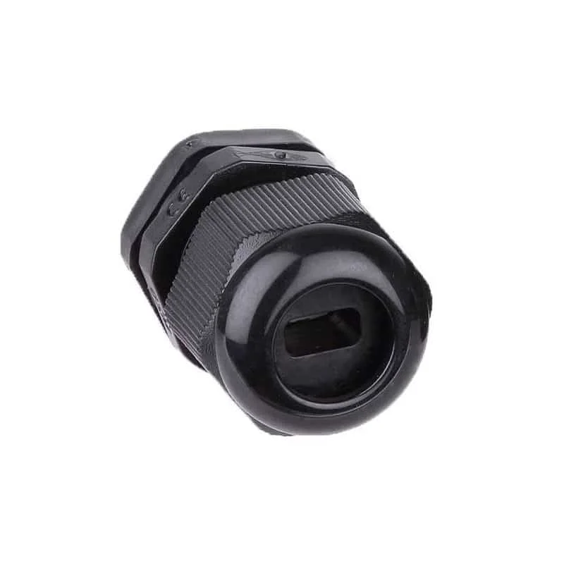
Cable sealing closes the path around the cable jacket. Entry sealing closes the body-to-enclosure joint. Cable retention resists cable movement relative to the gland. One assembly may combine the first and third functions in a compression element, while another uses separate seals and clamps. Locate the contact surfaces on the section drawing before selecting the variant.
Why do faces, edges and corners matter?
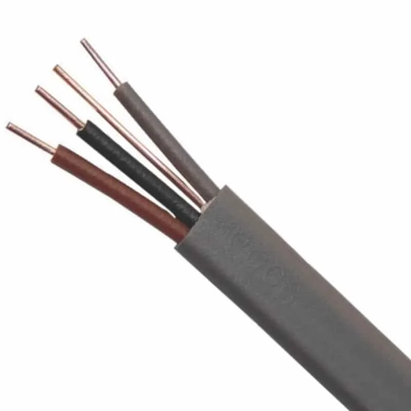
A flat jacket has broad faces, narrow edges and transitions between them. Compression must create suitable contact around this outline. A seal that bears on the broad faces while leaving gaps near the edges gives water or dust a route past the cable. Excess local pressure can also distort a soft jacket or load the conductors beneath it.
I compare the whole profile, including rounded corners, seams, ribs and conductor valleys. Two cables with the same maximum width and thickness can have different contact geometry. One may have a smooth oblong jacket; the other may have pronounced grooves between conductors. A shaped insert must suit those differences.
| Cable construction | Interface to identify | Selection direction |
|---|---|---|
| Smooth flat jacket | Broad faces, thickness and edge curvature | Match the shaped seal and its dimensional limits. |
| Rounded oblong or oval jacket | Complete outline and orientation | Compare with the specific gland’s accepted profile. |
| Ribbed or grooved outer surface | Valleys, raised features and available sealing land | Use a profile-specific interface that closes the relevant paths. |
| Exposed ribbon conductors or flexible circuit | Individual insulation, film edges and any intended seal zone | Use an entry system designed for that construction. |
| Several independent cables | Each cable’s jacket and movement | Use a suitable multi-hole or modular arrangement. |
The uneven and corrugated cable guide develops the same contact problem for ribs and valleys. At a flat entry, check the selected jacket layer and orientation before choosing how the seal should close.
Measure width and thickness at the sealing location
The sealing zone is the cable section that sits within the gland’s seal. Begin with the cable manufacturer’s drawing and its dimensional limits. Then inspect a representative sample at that location for seams, printing, damage and changes along its length.
Measure width across the broad dimension and thickness across the narrow dimension. Use a suitable instrument and contact force so the measurement does not flatten the jacket. Record the orientation and sample condition. A cable pulled tightly around a bend may present a different shape from the relaxed section intended for sealing.
NIST’s metrological traceability guidance connects measurement results to reference standards through calibration and uncertainty. For this selection, the practical question is whether the uncertainty is small enough to distinguish the cable from the stated limits. Near a boundary, apply the specified measurement and acceptance method rather than rounding a result into range.
Worked example: one nominal size, two different outcomes
Assume a hypothetical cable drawing specifies width 20.0 ± 0.3 mm and thickness 4.0 ± 0.2 mm. Its permitted intervals are therefore 19.7–20.3 mm wide and 3.8–4.2 mm thick. Assume two candidate inserts accept the same smooth rounded profile, but have the following dimensional windows:
| Hypothetical insert | Permitted width | Permitted thickness | Result for the full cable interval |
|---|---|---|---|
| A | 19.5–20.5 mm | 3.9–4.3 mm | Width fits; the minimum cable thickness is 0.1 mm below the lower limit. |
| B | 19.5–20.5 mm | 3.7–4.3 mm | Both dimensional intervals fit. |
In this hypothetical comparison, I found that both inserts accept the nominal 20.0 × 4.0 mm size, but only B covers the full permitted cable interval. A loses contact-range compatibility at the thinnest permitted cable before width becomes a problem. B retains 0.2 mm at each width boundary and 0.1 mm at each thickness boundary. Its thickness margin is the closer boundary, so that dimension deserves particular attention when comparing the next cable batch. These are dimensional margins, not seal-compression values.
I would continue with B and check its permitted jacket, edge radius, orientation and installed performance. The example assumes that each width-and-thickness combination within the window is permitted. If a product drawing specifies paired sizes or a curved profile envelope instead, compare the cable against that actual envelope.
For example, change only the cable edges from smooth curves to deep longitudinal grooves. B’s width and thickness may still fit, yet the grooves create different contact paths. That calls for a profile review or another insert. The example shows why dimensions narrow the choice while the full outline completes it.
What can an equal-area diameter tell you?
Equal-area diameter is the diameter of a circle having the same area as the chosen profile approximation. For a rectangular approximation with width and thickness , equating rectangle and circle areas gives:
Use millimetres for , and , giving area in mm². Rounded corners and grooves change the true area; the rectangular model describes an approximation to the outline.
Two hypothetical rectangular profiles, 20 × 4 mm and 10 × 8 mm, each have an area of 80 mm². Both therefore give an equal-area diameter of approximately 10.09 mm. Their physical widths and thicknesses are very different. A seal designed around the first profile cannot be selected for the second from that common number.
I use this calculation when comparing occupied profile area in an early layout. For passage through an opening, check the complete outline and orientation. For sealing, compare the actual contact perimeter with the shaped insert. Those are separate geometric tasks, even when they use the same cable dimensions.
When is a flat cable gland useful?
Use a flat gland where the selected cable has a non-circular sealing surface and must pass through a protected equipment boundary. Examples include suitable jacketed flat control cables, flat power cables and manufactured cable assemblies with a defined outer contact zone. Select the construction for the specific cable and equipment duty.
A shaped entry helps maintain the intended orientation at the wall. For example, a vertical flat cable entering a horizontal terminal row may need a change of direction inside the cabinet. I place the opening and support to leave room for that transition within the permitted bend directions, before fixing the gland orientation.

| Installation situation | What a flat entry can address | What to arrange alongside it |
|---|---|---|
| Flat control cable entering a cabinet | Profile contact and a defined exit orientation | Internal bend space, support and terminal approach. |
| Jacketed flat power cable | Entry sealing and the assigned cable-retention duty | Cable rating, electrical clearances and termination design. |
| Pre-terminated flat assembly | A suitable split or modular route around the assembly, where offered | Connector passage, split-joint sealing and assembly access. |
| Repeatedly moving cable near equipment | A fixed boundary connection suited to the cable | A separately designed moving span, support and strain management. |
| Replacement on existing equipment | A matched profile and mounting arrangement | Existing cutout, wall seal, cable route and inspection access. |
For a pre-terminated assembly, compare the connector’s passage envelope with the opening. A split entry may solve an installation-access problem, but its joints and module arrangement remain part of the sealing design. A one-piece gland normally needs the cable end to pass through before termination.
Flexible printed circuits, exposed ribbon conductors and laminated bus structures need an entry suited to their own insulation, edges and mechanical limits. Select those systems from the equipment and cable construction rather than treating every flat object as a jacketed cable.
Match the gland body to the enclosure
Entry compatibility means the body fits and seals at the intended enclosure opening. A flat cable-facing insert can sit in a body with a circular mounting thread, so the cable width does not directly specify the panel hole. Other designs mount through an oblong opening or a bolted flange.
For a threaded body, match the full thread designation and usable engagement. For a clearance hole with a locknut, compare the panel thickness, installed seal and accessory stack with the available thread. A flange needs its specified cutout, fastener locations and seating surface. Use the selected product’s mounting drawing for each route.
I check both sides of the wall before releasing the opening. The outside needs a sound sealing land and room for tools. The inside needs space for the retaining parts, cable bend and nearby terminals. Paint, burrs, curvature or a recessed opening can change how the entry seal seats.
| Mounting detail | Check on the actual enclosure |
|---|---|
| Thread or cutout | Size, shape, tolerances and orientation. |
| Wall | Thickness, flatness, coating and edge condition. |
| Entry seal | Correct part, seating land and installed compression. |
| Retaining parts | Locknut or flange fasteners, engagement and rear access. |
| Installed envelope | Tool clearance, cable bend and separation from adjacent hardware. |
Keep the wall seal in place when evaluating thread length. Removing an accessory to make a short body fit changes the mounting. Choose a suitable body length or approved mounting arrangement instead. The general cable-gland guide explains these enclosure-side functions across gland types.
Keep retention, bending and external support coordinated
Axial retention is resistance to movement along the cable’s length. Strain relief manages loads reaching the cable termination in the defined arrangement. A seal may contribute to grip, but the assembly’s assigned retention duty and cable support determine how it should be used.
A flat cable can have different bending behavior about its broad and narrow axes. Follow its specified bend directions and radii, including any separate limits for fixed installation and repeated movement. Plan the supported route so a tight edgewise bend or twist does not begin at the gland exit.
I position supports to carry cable weight and control movement while allowing the required bend. The gland should meet the load assigned to it in that design. Clamping the jacket harder to compensate for an unsupported cable can distort the seal zone without correcting the route.
IEC 60364-5-52:2009+A1:2024 addresses selection and erection of wiring systems. The entry, supports and terminations belong in the same installation review. For a moving machine cable, use the cable’s dynamic-duty requirements and the machine’s support arrangement, including inspection access at the fixed end.
Select the materials and required electrical functions
The jacket and seal remain in contact throughout service. Compare the actual materials with temperature, water, oils, cleaning agents, UV and other exposure. Chemical identity, concentration and contact conditions help choose the seal compound. The body, finish and enclosure also need a compatible material combination for the location.
I assess protective bonding and screen termination as identifiable paths through the entry. If armour or another conductive layer has an assigned protective duty, select its proper termination and enclosure connection. For an EMC screen, check the contact geometry and cable construction across the equipment’s relevant frequencies.
IEC 62153-4-15:2021+A1:2024 addresses transfer-impedance and attenuation measurements for connectors, cable assemblies and components. A screen-contact arrangement and a protective-conductor connection serve different electrical purposes, even when the same gland contains both.
For hazardous areas, match the exact model, cable construction, protection concept and accessories to the applicable certificate and installation conditions. IEC 60079-14:2024 addresses Ex installation design, selection, installation and initial inspection. Select the flat entry within that equipment arrangement.
Where fire performance is required, identify whether the requirement applies to the material, cable, component or complete installed system. Use the corresponding construction and assessment. The profile shape is a mechanical selection feature; the required environmental and electrical functions complete the specification.
Install and inspect the selected configuration
Before disturbing an installed electrical entry, qualified personnel should apply the site’s isolation procedure and make the equipment safe. Lay out the exact body, insert, seal and mounting accessories so their order and orientation are clear.
- Prepare the cable zone. Use the intended intact jacket section. Check seams, cuts, contamination and dimensions before it enters the seal.
- Prepare the enclosure. Confirm the opening and seating face. Remove burrs by the permitted method and preserve the specified surface protection.
- Align the profile. Orient the broad faces and edges with the shaped insert. Follow any keyed or asymmetric features.
- Close the two interfaces. Assemble the wall seal and cable-side mechanism using their specified tightening method. Counterhold the body where instructed.
- Support the route. Keep the cable’s bend and movement within its limits and prevent unwanted loads at the exit.
- Inspect the completed entry. Check seating, visible jacket distortion, retention arrangement, electrical connections and the required ingress verification.
IEC 60529 provides the enclosure IP classification framework. For the chosen entry, compare its stated cable, seals, mounting and water-test conditions with the installation. The IP selection guide explains the different exposure categories.
When comparing a test configuration, identify the cable or shaped specimen that represents the sealing surface and grip. For example, a smooth rigid test piece does not deform like a soft grooved jacket under the same closing movement. Compare those contact conditions and keep the applicable cable profile and installation method with the selected part.
After cable replacement, recheck width, thickness, edge shape and jacket material even if conductor count is unchanged. If leakage appears, inspect both the cable contact and wall seal. If the cable moves, check the gripping parts and support route. Correcting the affected interface gives a more useful repair than repeatedly tightening every nut.
Conclusion
I choose flat cable glands by following the real cable outline into the enclosure. Width and thickness establish the dimensional shortlist; edges, grooves, jacket and orientation determine the seal contact. The tolerance example shows how a small thickness difference can remove an otherwise plausible candidate.
Then match the body to the opening and plan the supported cable route. Select the materials, retention and electrical functions for the actual service duty. Keeping those decisions together makes the gland easier to install correctly and easier to replace without losing the reason it was chosen.
FAQs about flat cable glands
When should I choose a flat cable gland?
Choose one when a non-circular cable needs a shaped sealing or gripping interface at an enclosure. Compare its full width and thickness intervals, edges, jacket and orientation with the selected insert. Then check the body mounting, support route and required service functions.
Can a round-bodied gland accept a flat cable?
A round outer body can contain a shaped insert for a flat cable. Select the exact insert and cable profile covered by that construction. The body’s appearance and mounting-thread size describe different features from the cable-side sealing outline.
How should I use equal-area diameter for a flat cable?
Use it for an explicitly defined geometry or area comparison. A 20 × 4 mm rectangle and a 10 × 8 mm rectangle both give 80 mm² and about 10.09 mm equal-area diameter, while their outlines differ. Retain actual width, thickness, corners and grooves for opening and seal selection.
Can several separate cables share one flat slot?
Select a multi-hole or modular arrangement designed for the individual cables and their movement. Separate cables introduce contact paths between them, so each needs its intended sealing interface. A single flat-jacketed cable has a different outer boundary from loose cables placed side by side.
What should I check when replacing a flat cable?
Compare the new cable’s dimensional limits, edge shape, seams, jacket material and sealing zone with the installed insert. Recheck orientation, bend space and support, then inspect both the cable and wall seals and any required electrical connections. An unchanged core count does not ensure the same external profile.
Sources and technical references
- IEC 62444:2010 — Cable glands for electrical installations, accessed 2026-10-29.
- NIST — Metrological Traceability: Frequently Asked Questions and NIST Policy, accessed 2026-10-29.
- IEC 60364-5-52:2009+A1:2024 — Selection and erection of wiring systems, accessed 2026-10-29.
- IEC 62153-4-15:2021+A1:2024 — Transfer impedance and attenuation measurements, accessed 2026-10-29.
- IEC 60079-14:2024 — Ex electrical installation design, selection, installation and initial inspection, accessed 2026-10-29.
- IEC 60529 — Degrees of protection provided by enclosures, accessed 2026-10-29.