

The right cable-gland material needs to suit the local fluids, temperature, weather and mechanical loads. Each exposure can affect a different part: the body and finish, seals, washers, threads, cable jacket and enclosure interface. I compare the complete entry because a surviving metal body cannot compensate for an incompatible seal or jacket. Governing equipment and facility requirements add further constraints.
For the relationship between individual parts, the component-level cable gland material comparison compares body and finish, seals and washers, locknuts and accessories, enclosure and jacket together.
Key takeaways
- Name each medium, concentration, contact mode, temperature, duration, and combination.
- Compare normal operation, cleaning, shutdown, transport, abnormal events and maintenance as distinct exposures.
- Map every exposure to the body, seals, washers, threads, cable, and enclosure interfaces it can reach.
- Eliminate a candidate when its exact configuration conflicts with a named condition.
- A material name or general rating leaves the actual medium, temperature and contact conditions unspecified.
Local exposure determines material suitability
Suitability depends on what reaches the cable entry, how contact occurs, its temperature and duration, and any simultaneous agents. Those conditions can affect the body, seals, cable and panel interface differently. Credible abnormal exposure matters too when the entry must remain functional through it.
“Outdoor,” “marine,” “food plant,” and “chemical area” name locations. They do not define the exposure at an entry. Two glands on one enclosure may receive different spray, sunlight, drainage, heat, or maintenance. Materially different locations therefore need separate compatibility assessment, even on the same enclosure.
Site observations, process information, safety data sheets, cleaning instructions, heat studies and equipment drawings help establish the actual exposure. A conflict between these sources leaves the service condition uncertain until it is resolved.

Chemical and cleaning exposure
Chemical compatibility depends on the medium’s formulation, concentration and impurities, together with temperature, contact duration and frequency. Immersion, splash, vapor, mist and wiping expose parts differently. Rinsing, drying, residue and mixtures can also matter: a hot cleaning cycle differs from process exposure, and shutdown or maintenance may wet normally dry parts.
ASTM D543-21 evaluates plastics against chemical reagents under defined practices. I match specimen, reagent, temperature, exposure, conditioning, and measured changes to the intended service and acceptance limits. Confirm the supplied compound and condition. A plastic specimen does not prove another molded gland, seal, coating, jacket, or complete entry. “Oil resistant” and general compatibility charts provide screening leads.
For example, a washdown location may see a detergent, a disinfectant, hot rinse water, drying, and process residue in sequence. Keep that sequence rather than listing only the strongest-sounding chemical. Another enclosure may experience only vapor, but the vapor can condense on a cooler entry during shutdown. That condensation route can expose parts that remain dry during normal operation.
Temperature and time act together
Operation, cleaning, shutdown, transport and storage can have different temperatures and durations. Peaks, repeated cycles and rapid changes may load an entry differently from steady heat. Local heat sources, solar heating, cold surfaces and the energized state determine the temperature reached at the gland and jacket.
I link each medium and load to its temperature. A minimum-to-maximum range can hide timing and combined exposure. Seals, threads, coatings, jackets, and bodies may respond differently to steady heat and rapid cycles. Check the exact grade, compound, assembly, and duty. Reject a candidate whose limits or evidence do not cover that condition.
What weather, UV, salt, and humidity inputs matter?
Weather exposure combines radiation, temperature, water, contaminants, drying, shelter and orientation. Direct or filtered sunlight, enclosure color, shade, rainfall, spray, pooling and freeze-thaw conditions change the local duty. Airborne deposits and whether the entry can dry also matter; a coastal label does not specify salt deposition, wetness, cleaning or mating metals.
ASTM G154-23 covers fluorescent ultraviolet lamp exposure. Match the specimen, cycle, conditioning, property changes, and acceptance limits. The compound, colorant, reinforcement, and exposed shape must represent the supplied part. The hours do not convert into a universal outdoor life.
Salt spray addresses a different exposure. ASTM B117-26 sets apparatus conditions; it does not select gland specimen, duration, defect preparation, inspection, or acceptance. It gives no field-life conversion. I compare the test with the actual atmosphere and wetting on the exposure map. The ASTM B117 evidence guide explains the test-to-claim limits.
Humidity effects also depend on time and temperature. IEC 60068-2-30:2025 describes cyclic damp heat: high humidity and temperature changes that generally create surface condensation. The product or project specification sets specimen, severity, state, recovery, measurements, and acceptance. An IP (ingress protection) code does not replace that evidence. Appearance alone does not establish corrosion resistance.
Galvanic and crevice interfaces
Galvanic corrosion requires conductive materials in electrical contact with an electrolyte—a liquid that can carry ionic current. The body or coating, enclosure, locknut, washer, earth accessory and fasteners can form different pairs. Relative contact areas, scratches, crevices, drainage and deposits affect those interfaces, so a coated steel panel, aluminum plate or stainless wall gives the same gland a different corrosion context.
ASTM G71-81(2024) covers galvanic corrosion tests for dissimilar metals in electrical contact in a low-flow electrolyte. Galvanic corrosion arises from that electrochemical coupling. Match the actual pair, relative areas, electrolyte, temperature, oxygen access, and surface condition. A generic galvanic series is not assembly approval. Keep stress-corrosion cracking separate; the brass stress-corrosion assessment covers alloy, tensile stress, and cracking environment.
Crevices matter because washers, threads, seals, coatings, and retained deposits can create local conditions unlike an open surface. Mounting orientation and water traps determine where liquid and deposits remain. A salt-fog result on a flat coupon cannot silently prove a threaded, coated, assembled interface.
Mechanical duty and cable interfaces
Mechanical duty includes installation load, cable pull, side load, bending, vibration, shock, impact, thermal movement, enclosure flexure and maintenance disturbance. Fixed and moving cable routes need different support, and service access affects how the entry can be assembled or reopened. An industry label does not specify these loads.
Map the mechanical duty to the whole entry. A body material property cannot prove thread integrity, cable retention, seal compression, armour termination, strain relief, or panel-interface stability. IEC 62444:2010 supplies construction and performance requirements for complete cable glands within its scope. Use complete-product evidence where the required function belongs to the assembly. The exact cable, entry, accessories, installation instructions, and test configuration still control transfer to the proposed application.
The cable jacket is also part of the environment-facing interface. Its construction, diameter range, roundness, temperature and chemical exposure, movement and prior aging affect fit and compatibility within the manufacturer’s limits. Seal compatibility and cable-jacket behavior can limit a configuration even when the body survives. The seal cold-flow evidence guide explains why a material coupon cannot predict retained sealing contact in a complete gland.
Regulatory and facility constraints
Applicable constraints include the jurisdiction, facility specification, equipment standard, certificate or listing requirement, hygiene rule, fire requirement, hazardous-area protection concept, environmental restriction, and document edition. Identify which condition each rule limits and what evidence it accepts. Do not translate “food,” “rail,” “marine,” or “Ex” into a preferred body material.
Rules can affect more than the substrate. They may constrain compounds, additives, plating substances, exposed threads, cleanability, surface condition, traceability, certificates, marking, cable construction, or installation. The applicable specification determines which of these conditions the entry must meet. A material name cannot establish end-product compliance.
A required certification needs to cover the actual product construction, conditions and installation. A material declaration applies only to its identified material or component; it does not establish the complete product’s approval. Never use a factory management certificate as product evidence. The offshore gland standards guide shows how project, equipment, hazardous-area, ingress, material, and documentation requirements remain separate in one demanding environment.
Exposure affects several cable-entry parts
One service condition can affect several parts through different mechanisms. The table links common exposures to the interfaces and results that matter for material selection; an unknown condition leaves compatibility unanswered.
| Exposure | Affected parts and interfaces | Relevant comparison | Selection limitation |
|---|---|---|---|
| Chemical or cleaning sequence | Body, finish, seal, washer, cable jacket, enclosure | Exact material state, medium, temperature, contact and measured property | A known incompatibility rules out the affected material; unmatched conditions remain uncertain. |
| Temperature and time | Complete gland, seals, cable, panel interface | Simultaneous thermal duty and the operating or storage state | An exceeded limit or unrepresented state prevents relying on the stated range. |
| UV, weather, salt, humidity | Exposed body, coating, seals, labels, cable, mating surfaces | Method, specimen, cycle and property change relevant to the location | Failed criteria limit suitability; test hours do not establish field life. |
| Galvanic or crevice conditions | Body/finish, enclosure, locknut, washer, accessories | Metal pair, electrolyte, geometry and surface state | A different pair or retained-liquid path can change corrosion behavior. |
| Mechanical and regulatory duty | Complete entry | Product function, construction and approval scope | Missing required coverage or a construction mismatch leaves the duty unmet. |
One exposure may affect several parts and need several types of evidence. I keep material data, component tests, complete-product tests, and end-product approvals separate. A result needs to represent the actual specimen, conditions and required function. A coupon result—a material specimen test—cannot independently establish ingress, retention, EMC (electromagnetic compatibility), bonding, fire, hygiene, or hazardous-area suitability.
The NIST Alloy Data program records experimental alloy data with purity, processing, and uncertainty context. Before comparing exposure data, match the grade or compound, finish and condition to the supplied part. Check how the specimen was processed and how much uncertainty applies to the measurements.
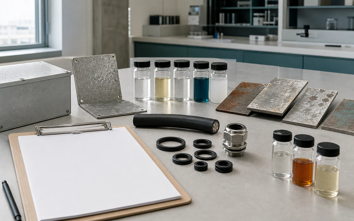
Choose the right cable gland material from the exposure map
A material with a known incompatibility, exceeded limit or failed applicable test cannot meet the required duty. Out-of-scope or expired approval, a prohibited substance or an unassessed substitution can also rule out a candidate. Price or availability cannot resolve those conflicts.
Missing exposure information leaves a specific compatibility question unanswered. For example, a material may resist a fluid under one condition while the required concentration, temperature or contact mode remains untested. Absence of a reported failure does not establish suitability.
Compare complete assemblies under the same service conditions and technical tradeoffs. A suitable body, seal, jacket and enclosure interface need to meet their own functions and applicable approval requirements; that does not make the material family a universal winner.
How exposure changes the material choice
The following relationships help connect the local duty to a complete material choice:
- Location changes exposure. Orientation, shelter, process conditions, cleaning, temperature and moisture can differ between nearby entries.
- Contact conditions change compatibility. Chemical identity, concentration or formulation, contact mode and temperature determine what reaches each surface.
- Sequence matters. Simultaneous agents or exposure order can produce conditions that separate maxima do not represent.
- Every exposed part has a role. Body, finish, seal, washer, locknut, accessories, enclosure and jacket can have different material limits.
- Mechanisms differ. Corrosion, swelling, cracking, embrittlement, coating loss and creep need relevant observations or tests; exposure alone does not prove damage.
- Comparison needs matching conditions. Specimen, method, measured property and product configuration determine what a result represents.
- Compatibility has limits. A known conflict rules out the affected arrangement, while missing necessary conditions leave suitability uncertain.
- Changes can alter the choice. A different cleaner, concentration, thermal cycle, cable, enclosure, finish or seal can change an interface that previously suited the duty.
The useful outcome is a compatible set of body, finish, seals, washers, threads, accessories, cable and enclosure interface for the local duty. Knowing which condition limits each part makes the choice more useful than a generic claim that one material suits an entire industry.
Conclusion
I select cable-gland materials from named local exposures. Define media, concentrations, contact modes, temperature and time, UV (ultraviolet radiation), wetting, cleaning, loads, and governing constraints. Map each condition to every body, seal, washer, thread, cable, and wall interface it reaches.
Compare complete assemblies under the actual service conditions. Known conflicts call for a different part or arrangement; missing exposure or performance information leaves suitability uncertain. A material-family name, compatibility label or general rating cannot supply those details.
FAQs about choosing cable gland materials by environment
Can cable gland material be selected from “indoor” or “outdoor” alone?
No. Those labels omit chemical, thermal, weather, mechanical, maintenance, and regulatory detail. Conditions can change decisions.
How detailed should a chemical exposure record be?
Identify the medium, formulation, concentration, impurities, temperature, and contact mode. Add duration, frequency, rinse, drying, residues, mixtures, affected components, and credible abnormal exposure.
Does a salt-spray result prove marine service life?
No. The result belongs to the stated method, specimen, exposure, preparation, observations, and acceptance rule. ASTM B117 does not provide a universal field-life conversion.
Is stainless steel always the safest environmental choice?
No. The exact grade, surface, mating materials, crevices, chemicals, temperature, loads, seals, cable, manufacturing condition, and approval scope must match. Evidence is required.
What must be known before comparing material candidates?
Define the location-specific exposures, affected components and interfaces, applicable rules, exact candidate configurations, and elimination criteria. Keep any missing exposure or nonmatching evidence open.
Sources and technical references
- ASTM D543-21, Standard Practices for Evaluating the Resistance of Plastics to Chemical Reagents, accessed 2026-09-08.
- ASTM G154-23, Standard Practice for Operating Fluorescent Ultraviolet (UV) Lamp Apparatus for Exposure of Materials, accessed 2026-09-08.
- ASTM B117-26, Standard Practice for Operating Salt Spray (Fog) Apparatus, accessed 2026-09-08.
- IEC 60068-2-30:2025, Environmental testing - Damp heat, cyclic, accessed 2026-09-08.
- ASTM G71-81(2024), Standard Guide for Conducting and Evaluating Galvanic Corrosion Tests in Electrolytes, accessed 2026-09-08.
- IEC 62444:2010, Cable glands for electrical installations, accessed 2026-09-08.
- National Institute of Standards and Technology, NIST Alloy Data, accessed 2026-09-08.