

Cable gland durability testing compares how well an installed entry keeps its sealing, retention and electrical functions after defined exposure. For a useful ten-year estimate, connect the site’s conditions to the failure mechanism, then validate the time relationship with longer-term evidence. The strongest design is the one that retains the required functions under the application’s actual stresses.
I start with the complete entry and the failure that would stop it doing its job. That choice determines the specimens, exposure and measurements. It also keeps a good-looking finish from masking a weak seal or a loose cable.
Key takeaways
- Test the gland with its cable, entry, seals, accessories and intended installation method.
- Give candidates comparable exposure and measurements while following each product’s assembly instructions.
- Accelerate the same failure mechanism that matters in service; excessive stress can change the mechanism.
- Measure sealing, retention and any required electrical function before and after exposure.
- Use the model’s uncertainty and every specimen’s outcome when judging a ten-year estimate.
Define the entry and the functions it must retain
Durability is the ability to retain required functions through a stated period of use or exposure. For a cable entry, that can mean keeping water out, holding the cable, preserving a bonding path and leaving the threads serviceable. A plated coupon answers a corrosion question; a complete installed entry answers questions about those functions working together.
Start with the body and finish, seal formulation, cable construction and measured diameter. Record the panel, entry thread or hole, washer, locknut, earth parts and assembly method. IEC 62444:2010 covers complete cable glands as supplied. Use the declared gland configuration as the starting point for the durability program, then include the service exposures that matter to the installation.
I set measurable limits before testing: acceptable ingress, cable movement, contact resistance, cracking or another relevant endpoint. This makes a change meaningful. Discoloration may be acceptable in one application, while a small loss of electrical continuity is a failure in another. The IEC 62444 selection guide explains how the complete gland configuration relates to its declared functions.
Build a fair cable gland durability testing comparison
A head-to-head comparison applies a common service requirement to different candidates. Keep the cable, mounting and exposure comparable, and document any necessary differences. For example, two gland designs may require different tightening torques or seals. I follow each product’s specified installation method and record the setting; forcing an identical torque could leave one loose and damage the other.
When the question concerns one material or coating, isolate that factor as far as the design allows. When it concerns two complete products, the result compares their assembled designs. These are different experiments.
| Control | What to keep comparable | What to record for each candidate |
|---|---|---|
| Specimens | Size and intended duty | Reference, lot, material, finish, seal and accessories |
| Cable | Construction, diameter range, surface and preparation | Actual diameter, insertion depth and any armour or screen |
| Mounting | Panel, entry, seating surface and cable support | Thread or hole, thickness, washer and locknut |
| Assembly | Correct installation and controlled tools | Product-specific sequence, tightening setting and lubricant state |
| Conditioning | Storage, pre-ageing, temperature and moisture | Initial condition before exposure |
| Exposure | Stress levels, sequence, duration and recovery | Chamber position, interruptions and actual monitored conditions |
| Measurements | Methods, intervals and failure limits | Baseline, instrument, uncertainty and result for each unit |
Use repeat specimens to reveal variation between units. Randomize chamber position or loading order where gradients could affect the result. For visual ratings, hiding the candidate’s identity can reduce judgement bias. Keep all units in the results, including failures, withdrawals and survivors.
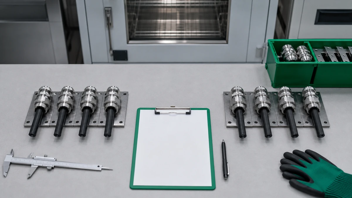
Before exposure, mount equivalent panel specimens with comparable cable spans and separate supports. Measure the intact jacket at the same defined section. I mark reference locations so later checks measure change in the specimen rather than change in the setup.

Match the exposure to a service failure mechanism
A failure mechanism is the physical or chemical process that causes a function to deteriorate. Heat can age a seal; temperature cycling can move a joint; vibration can move a cable or wear a contact. Salt, cleaners and sunlight create other routes to damage. Choose laboratory conditions from the actual location and duty.
| Service stress | Change to investigate | Useful functional check |
|---|---|---|
| Heat and temperature cycling | Seal ageing, contact-force loss or joint movement | Sealing, retention and joint condition after a defined recovery period |
| Sine or random vibration | Loosening, cable motion or contact wear | Cable displacement, entry rotation and continuity |
| Salt or chloride contamination | Damage to coatings, exposed metal and joints | Corrosion location, thread condition and any required bonding function |
| Cleaning fluid or process chemical | Seal swelling, cracking or coating attack | Dimensions and sealing after the specified contact and recovery |
| Sunlight, humidity and water | Surface ageing and changes in exposed polymers | Cracking and retained sealing or mechanical function |
I choose stress levels that speed the relevant change while keeping the same mechanism. Raising temperature until a normally firm part melts, for example, answers a different question from slow ageing in a warm cabinet. Check damaged specimens to see whether the laboratory and service failures have the same physical features.
Use the operating-temperature guide to connect temperature history with seal behaviour. The field-to-laboratory vibration guide helps define the waveform, spectrum, axes and support geometry for a mounted entry.
Convert accelerated time with a validated model
An acceleration factor relates the time to the same failure at the test condition and the use condition. The NIST Engineering Statistics Handbook describes physical acceleration as speeding the same mechanism. Different mechanisms can have different factors, so a seal-ageing factor does not also describe corrosion or loosening.
For a constant factor, . Here, both times use the same unit, and AF is dimensionless. Establish the relationship from data at relevant stress levels, then check it against independent lower-stress or service observations.
Worked example: what an acceleration factor of 10 means
Assume a validated AF of 10 for one seal-ageing mechanism and a constant test condition. This is a hypothetical calculation, not a measured cable-gland result. Use continuous operation and a 365-day planning year:
- A 1,000-hour test corresponds to 10 × 1,000 = 10,000 hours on that model’s use-condition timescale, or about 1.14 years.
- Ten planning years contain 10 × 365 × 24 = 87,600 hours. The corresponding test duration is 87,600 ÷ 10 = 8,760 hours.
A specimen surviving that duration is one observed survivor. Estimating the population’s reliability still uses the sample size, failures and model uncertainty. Other failure mechanisms require their own analysis.
NIST’s polymeric-component service-life research combines laboratory ageing, material measurements and field observations for photovoltaic components. That workflow is useful for planning seal studies: track the material change and the function it affects. For a cable entry, separate seal ageing from jacket deformation, joint movement and loss of contact force. The seal cold-flow guide explains the role of sustained loading and geometry.
Test stress interactions in a realistic order
Stress sequence is the order in which exposures act on a specimen. A cleaner may swell a seal before vibration moves the cable. Temperature cycling may open a coating defect before salt reaches the metal. The sequence can therefore change which design performs best.
I use separate stress branches to identify the cause of damage, then combine exposures where the service duty supports an interaction. A combined test can reproduce interacting effects but makes the cause harder to isolate. Keep the single-stress results available for comparison.
Thermal cycles, vibration hours and salt-fog hours remain separate histories. Add their effects through a model that represents the relevant interaction, rather than adding the elapsed times. If ageing changes the seal’s response to movement, measure that response after ageing and compare it with an unaged control.
Measure function at the same reference points
A failure criterion is a measurable boundary between acceptable and failed performance. Choose it from the required function before the test begins. Appearance can help locate damage, but the decision should follow the function: a clean-looking gland can leak, while a discoloured body may still meet every requirement.
| Function | Measurements to consider |
|---|---|
| Cable-facing seal | Leakage or ingress with the specified cable, diameter, seal and assembly |
| Retention | Cable displacement or load response under the chosen acceptance rule |
| Entry joint | Rotation, seating, thread condition, panel damage and entry sealing |
| Armour or screen termination | Movement, contact condition, continuity or shielding performance as applicable |
| Materials and finishes | Cracks, swelling, dimensional change and corrosion location |
| Serviceability | Thread or part damage after permitted disassembly, where reuse is required |
I measure before exposure and at intervals that can show when the change starts. Use the same recovery period each time: a hot, wet or swollen seal can behave differently after it cools or dries. Keep the complete entry assembled for checks that depend on its installed state.
For axial movement, secure the panel reference, support the cable and place the probe against the same collar face along the cable axis. Record the relative position and conditioning state. Compare the change with both the failure limit and measurement uncertainty.

Use salt-fog and vibration tests for the questions they answer
ASTM B117-26a defines a controlled salt-fog environment for comparing metal and coated-metal specimens. Specify the specimen, exposure duration and evaluation criteria in the test plan. Replicates help show the variation in corrosion response.
I compare corrosion location and functional damage as well as appearance. A coating result can guide the next material or finish choice. Estimating outdoor service life also requires relevant long-term exposure evidence; salt-fog hours alone have poor standalone correlation with natural environments. The ASTM B117 cable-gland guide explains how to define the specimen and interpret the result.
IEC 60068-2-6:2007 addresses sinusoidal vibration, while IEC 60068-2-64:2026 addresses broadband random vibration. Choose the method from the application’s motion, then specify frequency content, level, axes, duration, mounting and cable support. Check the functions before and after the exposure so a visible lack of damage does not hide a loose entry or unstable contact.
Interpret failures and surviving specimens together
Right-censored data describe units that remain operating when their observation ends. The exact later failure time is unknown. NIST’s guidance on censoring distinguishes those run-times from known failure times and failures detected between inspections.
For example, suppose ten specimens run for 1,000 hours. Two fail at known times and eight remain functional. Analyse the two failure times together with eight censored observations at 1,000 hours. Giving the survivors a failure time of 1,000 hours would change the data; omitting them would discard useful operating history.
I separate leakage, corrosion and contact loss when their mechanisms differ. Also check whether chamber position or one unusual specimen explains the apparent ranking. When the estimated difference is small compared with its uncertainty, extend the exposure or improve the sample plan before ranking candidates. Choose specimen count from the variation, difference worth detecting, confidence target and expected number of failures.
Choose the design that retains the required functions
Compare candidates against the same application requirements, then examine which mechanism caused each failure. A result is most useful when it leads to a design choice or a specific next test.
| Result | Practical interpretation |
|---|---|
| One design reaches a functional limit earlier | Compare time to that limit under the common test conditions |
| Both survive with little measurable change | Extend the test or sharpen the measurement if a ranking is needed |
| Designs fail by different mechanisms | Check which stresses occur in the intended duty and verify all required functions there |
| Laboratory and service failures match | Evaluate the life model and its uncertainty for that defined use profile |
| Field behaviour reverses the laboratory ranking | Revisit the stress level, mechanism or installation represented in the test |
Consider two hypothetical designs. A keeps its seal after thermal cycling but exceeds the corrosion limit. B meets the corrosion limit but leaks after thermal cycling. If the intended duty includes both exposures, neither meets the full requirement. Improve the weak feature and repeat the affected functional tests. For a different, less demanding duty, test that defined profile before treating either design as suitable.
I use a ten-year estimate when the model, validation and uncertainty describe the selected entry and service profile. Keep the required reliability level with that estimate: a predicted life distribution and an individual specimen’s survival answer different questions. The long-term durability guide explains how field history and maintenance affect the comparison.
Conclusion
Useful cable gland durability testing follows the function from installation through exposure. Match the cable and mounting, install each candidate correctly, apply the service-related stresses and measure the same endpoints. This reveals whether sealing, retention, electrical contact or corrosion controls the choice.
I start a ten-year assessment with that controlling mechanism, then check its acceleration model against longer-term observations. The worked example shows why the factor and duty matter as much as chamber duration. Keep failures and survivors in the analysis, and choose the design that meets every required function in the defined application.
FAQs about cable gland durability testing
Does one year of accelerated testing equal ten years of industrial use?
That relationship applies only when a validated acceleration factor of 10 represents the relevant failure mechanism and use conditions. Establish the factor from stress-life data and independent observations. Include specimen variation and model uncertainty when estimating reliability over ten years.
Can the most severe test identify the most durable cable gland?
Use a stress that accelerates the service failure mechanism. Excessive heat, load or chemical concentration can create a different failure and change the ranking. Compare the physical damage with service observations and keep mounting and cable support representative.
How many specimens are needed for a head-to-head comparison?
Choose the count from expected variation, the difference worth detecting, the confidence target and the failures expected within the test duration. Include separate stress branches and destructive measurements in that plan. Analyse every valid failure and survivor, and explain withdrawals or invalid runs.
Does passing salt-spray testing prove ten-year corrosion resistance?
Passing establishes the specified specimen’s result under that salt-fog exposure and acceptance rule. A ten-year outdoor estimate also needs relevant long-term exposure evidence and a supported relationship to service conditions. ASTM B117 describes the salt-fog method rather than a calendar-life conversion.
What should be measured after accelerated durability testing?
Repeat the required sealing, retention and electrical checks using the baseline methods and recovery conditions. Inspect entry movement, threads, cracks, swelling and corrosion to identify the mechanism behind any change. Include serviceability after disassembly when the intended maintenance plan requires reuse.
Sources and technical references
- IEC 62444:2010 — Cable glands for electrical installations, accessed 2026-10-28.
- NIST Engineering Statistics Handbook — Physical acceleration and modeling, accessed 2026-10-28.
- NIST — Service Life Prediction of Polymeric Components for Reliable Power Systems, accessed 2026-10-28.
- ASTM B117-26a — Standard Practice for Operating Salt Spray (Fog) Apparatus, accessed 2026-10-28.
- IEC 60068-2-6:2007 — Sinusoidal vibration testing, accessed 2026-10-28.
- IEC 60068-2-64:2026 — Broadband random vibration testing, official standard and redline edition, accessed 2026-10-28.
- NIST Engineering Statistics Handbook — Censoring, accessed 2026-10-28.