

“Wire gland size” and cable diameter are different fields. M20, for example, identifies an entry-thread interface. The cable must separately fit the gland’s published sealing and retention ranges. I would keep those fields separate from the first drawing check. There is no universal cable outside-diameter (OD) range for every gland with the same thread designation.
Key takeaways
- Replace the ambiguous term “wire gland size” with separate entry-thread, cable-seal, retention and body-dimension fields.
- Compare the cable’s full minimum-to-maximum OD interval with the exact gland table, not one nominal value.
- Metric, NPT and PG designations belong to different thread systems and are not cable diameters or direct equivalents.
- Armoured, multi-cable, corrugated, flat and screened constructions need more inputs than finished round cable OD.
- Check cable-side retention and sealing, the enclosure-side interface and any required electrical function separately.
What should “wire gland size” mean on a drawing?
Wire gland size is an informal phrase that can mean several unrelated dimensions. I recommend naming the component cable gland, then listing its interfaces separately. IEC 62444:2010 covers cable-gland construction and performance, including glands with IEC 60423 metric entry threads. It does not create a universal mapping from thread name to cable OD.
| Required field | Example format | Selection purpose |
|---|---|---|
| Entry thread | Full family, nominal size, pitch or taper, tolerance and usable length | Mate the gland to the enclosure hole, hub or adaptor |
| Cable sealing range | Minimum and maximum OD for the stated seal | Keep the cable jacket within the represented sealing interval |
| Cable retention or anchorage range | Minimum and maximum OD or cable-layer range | Transfer the declared pull or anchorage load through the intended layer |
| Through-bore or throat | Minimum clear passage where stated | Pass the cable end or connector without damage before sealing |
| Body and hex dimensions | Across-flats, maximum body diameter and assembled length | Provide spacing, wrench access and rear clearance |
| Armoured-cable ranges | Inner sheath, armour or braid and outer sheath | Fit every controlled layer in the armour termination |
Cable diameter is the measured outside dimension of the finished cable layer that enters the applicable gland seal or grip. It is not conductor cross-sectional area, conductor diameter, bend radius, thread diameter or panel-hole diameter. For a round unarmoured cable, the outer jacket OD is normally the first sizing input; the product drawing determines every additional input.
The cable-gland clamping-range criteria explain the difference between retention and sealing. Entry size and cable range need separate comparisons: a matching enclosure thread can still have an unsuitable cable seal.
Separate the entry thread from the cable range
An M20 gland has an M20 entry thread. It is not automatically a gland for a 20 mm cable. Conduit outside diameters and dimensional requirements for associated-fitting threads fall within IEC 60423:2007. The cable range remains a property of the exact gland body, seal set and cable construction represented by the manufacturer.
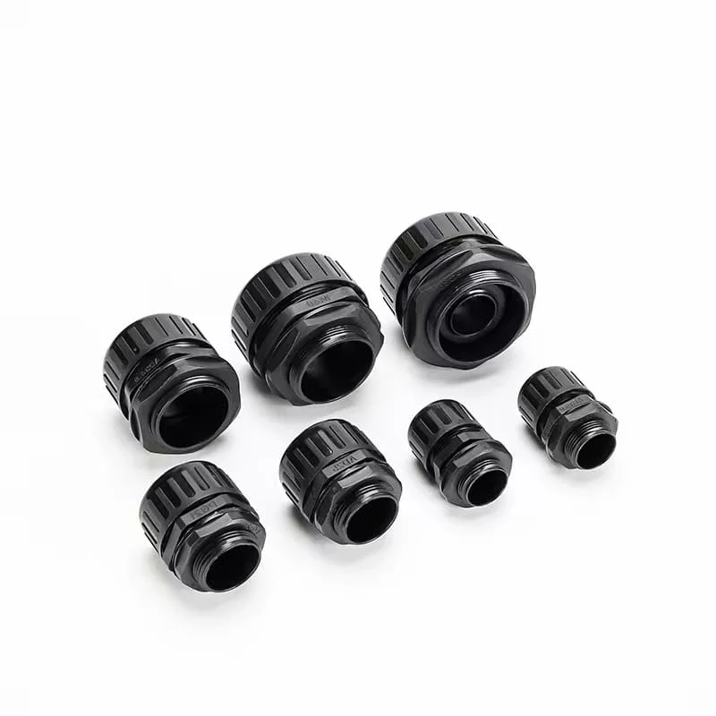
For ISO metric threads, the number after M is the nominal thread diameter and the value after the multiplication sign is the pitch when stated. The general plan is defined in BS ISO 261:1998, while basic dimensions for ISO general-purpose metric screw threads are defined in BS ISO 724:2023. These thread standards describe the mating geometry, not the gland’s elastomer range.
NPT uses nominal pipe-thread designations. Dimensions and gauging for NPT and related inch pipe threads are standardized in ASME B1.20.1. The nominal fraction is neither the measured male-thread OD nor a cable range. PG is another thread family with its own sizes. Compare the metric, NPT and PG thread geometries when resolving a mixed entry; do not replace one family with a close-looking diameter.
Build the cable OD interval before opening a gland chart
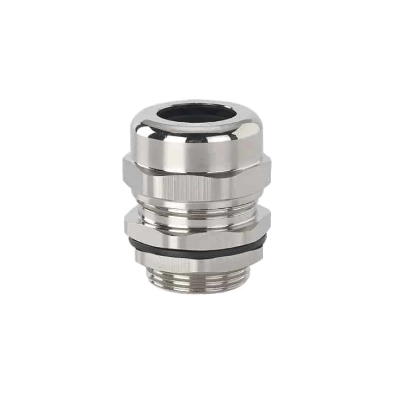
I would establish the cable’s full OD interval before choosing a gland. Obtain the manufacturer’s minimum and maximum finished OD for the ordered construction and revision. If the stated nominal value has asymmetric tolerances, convert the lower and upper limits into one interval. A single nominal diameter can miss either end of the gland range.
For incoming or replacement work, I recommend measuring a representative sample with a defined method. Use jaw force and contact geometry that do not flatten a soft jacket. Where ovality or surface texture matters, record several angular positions and locations along the cable.
BS EN ISO 13385-1:2019 covers calliper design and metrological characteristics—the characteristics relevant to measurement performance.
Measurement result is a value linked to its method, instrument, conditions, and uncertainty or stated decision rule. NIST metrological-traceability policy establishes traceability through a documented calibration chain. Naming a calibrated tool alone does not show that the sampled cable lot or the way its jacket was compressed is representative.
The cable details that affect the sizing decision are:
- Cable manufacturer, family, part number and drawing revision.
- Cable construction: round, flat, corrugated, braided, armoured, screened or composite.
- Nominal OD plus lower and upper manufacturing limits.
- Measured minimum and maximum across rotations and locations, where measurement is required.
- Jacket material, surface texture, seams, ribs and permitted compression.
- Installation and operating temperature limits relevant to the cable and seal.
- Connector or prepared end that must pass through the gland before termination.
- Static, flexing, torsional or side-load duty near the entry.
I would use the cable’s controlled limits and the gland’s declared ranges without adding an arbitrary percentage “safety margin.” If future cables are unknown, define the dimensions and constructions they may have as a new engineering requirement. Unused gland range alone does not guarantee that those cables will be compatible.
Compare the complete cable interval with the exact gland row
Accept the size only when the cable’s complete OD interval lies within every applicable product range. A nominal value at the middle of a range is insufficient if the upper cable limit exceeds the seal maximum or the lower limit falls below the retention minimum.
| Comparison result | Decision | Required action |
|---|---|---|
| Cable minimum and maximum both lie inside seal and retention ranges | Proceed to entry and application checks | Use that exact model’s current table for the remaining checks |
| Cable minimum falls below either declared minimum | Reject that configuration | Choose another seal insert or gland size documented for the lower limit |
| Cable maximum exceeds either declared maximum | Reject that configuration | Choose another documented range; do not force the cable through the seal |
| Cable interval touches a stated limit | Conditional | Confirm whether endpoints are inclusive and whether tolerances or test variants impose another restriction |
| Two gland rows both contain the cable interval | Compare complete configurations | Select by entry, retention class, seal design, material, installation access and represented tests |
| No row contains the full interval | A different configuration is needed | Change the gland, seal insert, cable specification or enclosure entry to obtain a compatible fit |
The seal range and retention range may differ. A cable can pass through the body and still fall outside one performance range. Likewise, a seal insert may cover the cable while the entry thread, body clearance or anchorage classification fails the project requirement.
Read the cable-gland size-chart columns from one product row. I would keep the manufacturer, family, seal material, cable construction, and table revision with each range. Combining several catalogues into a supposed “standard M20 range” loses the link to a real gland.
Read all columns in a gland size chart
Begin with the exact part number, not the first row whose thread appears familiar. A usable chart should identify or link to the following:
- Product family and material or seal variant.
- Complete entry thread designation and usable length.
- Minimum and maximum cable sealing range.
- Minimum and maximum retention or anchorage range when different.
- Throat or bore dimension if a pre-terminated cable must pass.
- Body diameter, across-flats and assembled length.
- Panel-hole limits, washer and locknut requirements.
- Cable construction or armour layer represented.
- Installation torque or observable assembly end point for the exact size.
- Performance classifications, test conditions and certificate restrictions.
Terms such as “clamping,” “sealing,” “accommodation,” “bedding,” and “armour” describe different features. Use the drawing or instructions to identify what each column measures. If a chart gives one cable range without saying what it applies to, I would ask for clarification before treating it as both the retention and sealing range.
Never borrow a cable range from another body material or seal compound because the thread code matches. An M20 brass gland, M20 polymer gland, M20 armoured gland and M20 EMC gland can have different internal geometries and represented cables. Use the cable-gland data checklist to identify missing fields before ordering.
Add extra dimensions for special cable constructions
Finished round OD is sufficient only when the exact gland acts on that one round layer. Other constructions add independent interfaces:
| Cable or route | Additional sizing inputs | Common mistake |
|---|---|---|
| Steel-wire-armoured or braided cable | OD over inner sheath, OD over armour, armour wire or braid geometry, outer-sheath OD | Selecting from finished OD alone |
| Screened EMC cable | Screen type and diameter at contact, jacket strip length, permitted contact method | Treating the screen diameter as the jacket range |
| Multi-cable insert | OD interval for every cable and the assigned hole positions | Adding cable diameters and comparing the sum with one round range |
| Flat or oval cable | Major and minor dimensions, corner radius, orientation and dedicated seal geometry | Using an equivalent round diameter |
| Corrugated hose or conduit | Conduit family, profile, crest OD, jacket and fitting range | Applying a smooth-cable gland range to a conduit connector |
| Pre-terminated cable | Maximum connector envelope and gland assembly sequence | Checking the cable OD but missing passage clearance |
Assign every cable to a dedicated hole with the multi-cable sizing method. For armoured cables, use one gland row that contains the applicable inner sheath, armour and outer sheath ranges at the same time. Do not mix the inner-seal row from one size with the outer-seal row from another.
Cable routing also affects the installed interface after the nominal fit is correct. A bend or unsupported weight close to the gland can ovalize or side-load the jacket. Check the bend radius and seal load separately; the gland range remains a dimensional prerequisite rather than proof of acceptable routing.
Verify the enclosure hole, wall and installation space
The cable may fit the seal while the gland fails to fit the enclosure. I would first identify whether the entry is a tapped hole, a clearance hole with locknut, a threaded hub, or an adaptor. Then check the full thread designation, permitted hole, and usable engagement. Check the wall and coating stack, seating face, washer, and rear clearance separately.
Across-flats and maximum body diameter control gland spacing. Model the tool sweep and cable bend envelope, not only the nominal thread-centre spacing. Large adjacent caps, locknuts, earth tags and reducers can interfere even when both threads fit their holes.
Ingress protection applies to the complete enclosure arrangement. IEC 60529 classifies degrees of protection provided by enclosures. I would check which cable diameter, entry seal, hole or thread, wall, and assembly condition the evidence covers. A cable inside the gland range does not extend an IP result to an untested entry arrangement.
For North American projects, UL 514B covers applicable conduit, tubing, and cable fittings. I would match the listing, marking, and installation instructions to the cable and entry. The trade or thread label alone does not describe the listing’s scope.
Diagnose a fit problem by interface
Do not solve every installation problem by moving one nominal gland size up or down. Identify which interface failed:
| Observation | Likely interface to check first | Controlled response |
|---|---|---|
| Cable will not pass the loose components | Throat, insert bore or pre-terminated connector envelope | Verify assembly sequence or select a documented split/pass-through design |
| Cable enters but seal cannot reach its end condition | Cable maximum OD, seal variant, jacket hardness or component order | Check cable lot and exact seal range; replace mismatched parts |
| Tightened seal still permits cable movement | Cable minimum OD, retention range or wrong insert | Reject and select a represented retention configuration |
| Gland thread will not start in the enclosure | Thread family, pitch, taper, gender or damaged thread | Gauge or measure the entry; use a controlled adaptor or correct gland |
| Locknut has too little engagement | Usable thread length versus wall and accessory stack | Select a longer entry or approved mounting arrangement |
| Installed cable exits at a severe angle | Body spacing, bend envelope or support | Reposition or support the route before energizing the equipment |
| Ingress test fails while cable seal looks uniform | Entry-side seal, seating land, hole, adaptor or enclosure | Isolate and correct the enclosure interface |
Extra torque is not a sizing method. It can damage threads, cut the jacket, extrude a seal or conceal a wrong component order. Use the exact instruction and observable end condition for the selected part and cable.
Specify one complete gland-and-cable pairing
A compatible cable-and-gland pairing brings these details together:
- Cable manufacturer, family, part number, construction and revision.
- Nominal, minimum and maximum OD for every layer acted on by the gland.
- Measurement method and decision rule where incoming measurement is required.
- Gland manufacturer, family, exact part number, body and seal material.
- Sealing, retention, armour and screen ranges with table revision.
- Complete entry thread, usable length, tolerance or gauging requirement.
- Enclosure hole or hub, wall stack, seating face, locknut and entry seal.
- Maximum body, hex and assembled dimensions plus tool and cable-route clearance.
- Installation instruction revision, component order, preparation lengths and tightening end point.
- Required retention, ingress, bonding or EMC performance and any applicable listing or certificate reference.
Check the exact model and seal variant, even when two glands share an entry thread or look similar in size. Different inserts can give the same body a different cable range, so the full part number and seal-range data matter more than its visible dimensions.
Conclusion: match two ranges and one entry, not one size number
I would answer “wire gland size versus cable diameter” by separating three inputs. The cable supplies its minimum-to-maximum OD interval. The gland supplies its sealing and retention ranges. The enclosure supplies a specified thread or hole, wall stack, and seating condition.
Select the gland only when the complete cable interval fits every applicable range and the enclosure entry is compatible. I would add armour, screen, special-profile, and passage dimensions wherever the construction requires them. Those dimensions identify a compatible cable-and-gland pairing for the actual entry.
FAQs about wire gland size and cable diameter
Is an M20 cable gland intended for a 20 mm cable?
Not by designation alone. M20 identifies the nominal metric entry thread. The cable OD must fit the exact gland’s published sealing and retention ranges, which can differ between product families, body materials and seal designs.
Do all M20 cable glands have the same cable range?
No. The entry thread can match while internal bores, seals, inserts, retention systems and represented cable constructions differ. Use the manufacturer, family, part number and current table row for the ordered gland.
How should I measure a soft or oval cable for gland selection?
Use a defined low-force method that does not flatten the jacket. Record minimum and maximum values at several angular positions and longitudinal locations, then combine those observations with the cable manufacturer’s controlled OD limits and the project’s decision rule.
Should I choose the larger gland when a cable sits between two ranges?
Choose the configuration whose seal and retention ranges contain the cable’s complete OD interval and whose entry, material, access and represented tests meet the application. There is no universal rule to choose the larger or smaller nominal thread.
Are metric, PG and NPT gland sizes interchangeable?
No. They use different designation and thread geometries. Resolve the exact family, size, pitch or taper, tolerance and mating entry. A close measured diameter or a conversion table is not permission to mate unlike threads.
Sources and technical references
- IEC 62444:2010, Cable glands for electrical installations, accessed 2026-09-13.
- IEC 60423:2007, Outside diameters and threads for conduits and fittings, accessed 2026-09-13.
- BSI, BS ISO 261:1998, ISO general-purpose metric screw threads: General plan, accessed 2026-09-13.
- BSI, BS ISO 724:2023, ISO general-purpose metric screw threads: Basic dimensions, accessed 2026-09-13.
- ASME B1.20.1, Pipe Threads, General Purpose, Inch, accessed 2026-09-13.
- BSI, BS EN ISO 13385-1:2019, Design and metrological characteristics of callipers, accessed 2026-09-13.
- NIST, Metrological Traceability: Frequently Asked Questions and Policy, accessed 2026-09-13.
- IEC 60529, Degrees of protection provided by enclosures, accessed 2026-09-13.
- UL 514B, Conduit, Tubing, and Cable Fittings, accessed 2026-09-13.