

Proper grounding via cable glands keeps each assigned protective connection continuous through the cable entry and enclosure. I trace the intended current path before choosing a gland or investigating a fault. The protective conductor, armour and screen may meet the same assembly, but they have different jobs. A missing plate bond, a poor armour termination or an unintended parallel path calls for a different correction.
Key takeaways
- Identify the installation’s protective measure and earthing arrangement before interpreting a gland continuity result.
- Check both the cable-side connection and the enclosure-side connection when the gland forms part of a protective path.
- Assess armour for its assigned electrical duty; keep screen termination and EMC performance distinct from that duty.
- Account for paint, removable plates, accessories and parallel metalwork when locating a faulty joint.
- Restore the designed path, verify the affected functions and preserve the cable seal during the repair.
Before opening an enclosure, disturbing a bond or making a resistance measurement, use the site’s safe isolation procedure. Secure all relevant energy sources, address stored energy and prove exposed conductors dead with suitable equipment. HSE’s electrical safety guidance describes these precautions and the need for competent inspection and testing. Never remove a protective conductor from energized equipment to isolate a meter reading.
Proper grounding via cable glands: identify the current path
Protective bonding is an intentional electrical connection of conductive parts for safety. At a cable entry, a gland may join armour, an accessory and an enclosure into that path. In another design, a dedicated protective conductor may bypass the gland while the gland seals and retains the cable.
A protective-earth (PE) conductor performs an assigned protective function. Cable armour is a metallic layer used primarily for mechanical protection, with any protective-conductor duty assessed separately. A cable screen is a conductive layer used to control electromagnetic coupling and associated currents. Naming those functions makes a fault investigation more precise than calling every metal part “ground.”
| Part or route | Main question at the entry | What to follow beyond the gland |
|---|---|---|
| PE conductor | Is its intended termination and connection sound? | The complete protective route and protective measure |
| Armour | Is the correct layer captured by the intended clamp? | Its assigned duty, other terminations and route |
| Screen | Does the termination preserve the specified contact geometry? | The equipment’s EMC connection and cable arrangement |
| Gland and accessories | Which interfaces are intended to conduct? | Plate, enclosure, tag, jumper and earthing terminal |
| Protective device | Does the protection suit the circuit and fault conditions? | Device selection, settings and required response |
IEC 60364-5-54:2011+AMD1:2021 addresses earthing arrangements and protective conductors. IEC 62444:2010 addresses the complete cable gland. Use the installation design to assign the electrical route and the selected gland’s instructions to make the intended connection.
Establish how the installation responds to a fault
The earthing arrangement determines the return path and the protective response. In a TN arrangement, the intended fault-current return uses the supply protective conductor or protective-earth-and-neutral conductor, as explained in the IET protective-earthing guidance. An isolated plate cannot complete that route merely because its gland is metallic.
TT arrangements use an installation earth electrode and have different fault-loop conditions. The IET’s TT explanation describes why their typically higher loop impedance makes residual-current protection important. Establish the actual arrangement and adopted rules, including any IT, generator or multiple-source design, before deciding what a measured value means.
IEC 60364-4-41:2005+AMD1:2017 addresses protection against electric shock and coordination with external influences. The gland connection is one part of that protective system. The bonding and grounding guide covers the full route; the checks below focus on cable-entry faults that can interrupt or obscure it.
Locate an open or unstable enclosure-side connection
Start at the actual contact surfaces, including any removable gland plate. Paint, powder coating, anodizing, plastic washers and insulating plates can interrupt a route that looks metallic from the outside. Check the specified stack: body, washer, locknut, earth tag or bonding accessory, plate and enclosure connection.
Consider an armoured gland on a painted, removable plate. A meter may show a low reading from the gland to its earth tag: those parts touch. Yet the plate still needs a sound bond to the enclosure’s PE terminal. Paint at the mounting points can leave that bond open while the local gland reading looks good.
I follow each intended joint and place the probes across the part of the route under test. The site’s isolated test procedure sets how to do that safely. If a jumper is missing, restore the specified jumper. If an accessory is fitted wrongly, correct the stack. Keep the wall seal and corrosion protection intact. Then recheck the local joint and the complete route; the original gland-to-tag test alone would miss the plate fault.
Where the design permits them, an earth tag, bonding washer, bushing or dedicated conductor can provide the necessary connection. Their position and assembly matter. A sealing washer controls a liquid path; a retaining locknut provides mechanical restraint. Use each accessory for its declared purpose and follow the controlled contact-preparation and tightening instructions.
A nonmetallic wall requires a deliberate conductor route for any armour or accessory that needs protective bonding. The two-interface earthing method separates the cable-side termination from the enclosure-side connection so neither disappears inside a general continuity check.
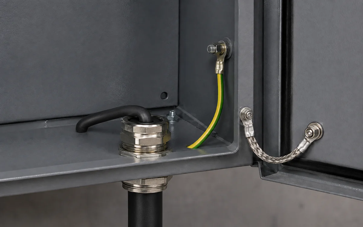
The illustration shows the metal gland, a green-and-yellow conductor at an enclosure stud, and a separate braided connection across the door joint.
Check an armour termination at both ends
An armour clamp must match the cable construction and the assigned electrical duty. Steel-wire armour, aluminium-wire armour, braid and tape require appropriate termination arrangements. First identify the actual layer and dimensions, using the armoured-versus-unarmoured gland guide where the construction is uncertain.
If the design uses armour as a protective conductor, assess its capability along with both terminations and any intermediate joints. The IET earthing and bonding FAQs explain that steel-wire armour used as a circuit protective conductor needs a sizing assessment accounting for its material and thermal constraints. Use the adopted installation method and cable data for that assessment.
I inspect how the armour is captured, whether the correct cone or clamp is fitted, and whether corrosion or movement has changed the contact. A firm mechanical grip is useful, but the complete route also has to carry its assigned fault duty. Restore the specified arrangement at the defective end and verify the affected route; improving one clamp leaves an open joint elsewhere unresolved.
Investigate EMC symptoms through the screen connection
Screen termination controls a different current path from protective bonding. Its geometry, cable construction and connection to the enclosure affect performance across frequency. When interference appears after entry work, compare the screen contact, exposed screen length, cable route and connection points with the intended equipment arrangement.
I keep that investigation separate from the PE checks. A low resistance at a screen contact does not describe its shielding behavior across frequency, and a good screen termination does not establish protective fault-current capability. IEC 62153-4-15:2021+AMD1:2024 addresses measurements such as transfer impedance and screening attenuation for connectors, cable assemblies and components. Those are different measurements from protective-conductor continuity.
If the same gland assembly performs both functions, preserve both during a repair. Follow the specified screen termination and maintain the required protective connection. The EMC shielding guide helps trace the interference source and coupling route without treating every noise symptom as a PE fault.
Find the parallel path behind an unexpected low reading
A resistance meter measures the connected network between its probes. Tray, conduit, another screen, structural metalwork or temporary connections can bypass the joint being investigated. I map those paths before deciding that a low reading confirms the intended connection.
For example, an enclosure may still connect to bonded conduit while its plate bond is open. Test current can reach the enclosure through that conduit and other metalwork. A low reading could therefore hide the broken plate bond.
I use a path-specific test planned by the competent person. Account for parallel routes; separate them only as the site’s safe procedure allows. Once the fault is fixed, check the repaired joint and the required complete route. Reconnect and verify every required bond before returning the equipment to service. This check distinguishes a sound local joint from a bypass through the rest of the installation.
Trace the cause of heat, discolouration or corrosion as well. Stray current, loose contacts, corrosion and heat from nearby conductors call for different repairs. Keep suspect equipment isolated while the competent person identifies the source. Tightening the gland alone can leave the electrical or environmental cause unchanged.
Use a resistance measurement for the function being checked
Choose test points and an acceptance limit that represent the intended protective route. IEC 61557-4:2019 covers equipment for measuring the resistance of earth, protective-earth and equipotential-bonding conductors, including their connections and terminals. Apply the instrument instructions and the installation’s verification procedure to the measurement.
I distinguish a local contact test from a complete-path test. Probes across an earth tag and gland body check that joint. Probes spanning the required protective route check more of the installation. Use stable contact points and account for test-lead resistance. Consider meter uncertainty and temperature when comparing the result with the specified limit.
The calculated margin is useful only for the measurement and limit entered. Keep the mapped parallel paths and test configuration with the result. Fault-current capability, loop conditions and protective-device response remain part of the installation’s protective design and verification, as described in the short-circuit protection guide.
Correct the fault and prevent it returning
Repair the failed interface while preserving the rest of the entry’s functions. Match the replacement gland and accessories to the cable, armour or screen, enclosure material, thread and environment. Follow the selected assembly’s torque, contact preparation and corrosion-control instructions. For a hazardous location, retain the required certified entry arrangement and its installation conditions.
| Observed problem | First distinction | Corrective direction |
|---|---|---|
| Continuity exists only at the gland | Does the plate connect to the required protective route? | Restore the intended plate or enclosure bond |
| Armour contact is loose or corroded | Is the clamp correct and is the other end sound? | Restore the specified armour terminations and assess the route |
| EMC changed after maintenance | Did the screen geometry or cable route change? | Restore the intended screen arrangement and assess EMC behavior |
| A low reading conflicts with visible damage | Is another conductive path bypassing the joint? | Use safe path-specific testing |
| The gland area heats or discolours | Is the cause electrical, mechanical or environmental? | Remove the cause and replace damaged parts as required |
After a repair, inspect the cable seal, wall seal, mechanical restraint and intended conductive contacts. The accessories guide explains how the individual washers, locknuts and tags fit into that assembly. Recheck affected connections after plate removal, cable replacement or a change in the contact stack.
Set inspection intervals from the environment and findings. HSE advises more frequent checks where deterioration is more likely and adjustment of the interval when faults are found. Moisture at a damaged coating, vibration at a loose joint or repeated maintenance can justify attention to a particular interface rather than a general glance at the gland body.
For lightning or static-control problems, follow the protection design for that hazard. The lightning-protection entry guide covers bonding and surge-protection boundaries. A resistance criterion selected for a different function should not replace the protective-conductor assessment at this entry.
Conclusion
I prevent cable-entry grounding faults by keeping the assigned paths visible: protective conductor, armour, screen, gland contacts and enclosure bond. When a fault appears, identify the affected function and locate the defective joint before replacing hardware.
Restore that joint with the specified parts and check the complete route under the site’s test procedure. Account for parallel paths and preserve the seals and support. Check the earthing system and protective-device response as well as the local bond.
FAQs about grounding and bonding at cable glands
Does every metal gland replace a PE conductor?
A metal gland can form one interface in an assigned protective route. Some installations use a dedicated PE conductor that bypasses it; others may use permitted cable armour as part of the route. The complete arrangement must meet the adopted electrical design and installation requirements.
What does an earth tag actually provide?
It provides a connection point when used in its intended assembly. Check its contact with the gland, conductor termination and connection to the required protective route. The presence of the tag alone leaves the plate bond, conductor capability and protective-system response to be assessed.
Can steel-wire armour serve as a protective conductor?
It can where the adopted rules and design permit it and its capability is assessed for the duty. Include the steel’s electrical and thermal behavior, both terminations and intermediate joints. Mechanical retention of the armour is a separate requirement from the complete protective route’s performance.
Why might a continuity reading hide a damaged gland joint?
Current can bypass the joint through conduit, tray, another screen or connected metalwork. Identify those routes and use the approved isolated testing procedure to assess the intended interface. Restore and verify every required protective connection before returning the equipment to service.
Does a good screen connection establish protective bonding?
Screen performance and protective bonding serve different functions. The screen arrangement must suit the equipment’s EMC requirements; the protective path must carry its assigned duty and work with the protective measure. When one gland serves both, assess and preserve each function separately.
Sources and technical references
- IEC 62444:2010 — Cable glands for electrical installations, accessed 2026-10-29.
- IEC 60364-5-54:2011+AMD1:2021 CSV — Earthing arrangements and protective conductors, accessed 2026-10-29.
- IEC 60364-4-41:2005+AMD1:2017 CSV — Protection against electric shock, accessed 2026-10-29.
- IEC 61557-4:2019 — Resistance of earth connection and equipotential bonding, accessed 2026-10-29.
- IEC 62153-4-15:2021+AMD1:2024 CSV — EMC transfer impedance and attenuation measurements, accessed 2026-10-29.
- HSE — Electrical safety frequently asked questions, accessed 2026-10-29.
- IET — Protective earthing webinar questions and answers, accessed 2026-10-29.
- IET — TT earthing considerations, 2021, accessed 2026-10-29.
- IET — Earthing and bonding FAQs, including steel-wire-armour CPC assessment, accessed 2026-10-29.