

I favor a short circumferential screen contact with a direct conductive route into the enclosure for 360° EMC shielding. A spring, cone or collet is a useful candidate for supported braid; foil needs a termination designed for its construction. I choose among them by screen fit, assembly consistency and response across the required frequency band. Include the panel joint and accessories in that comparison.
EMC means electromagnetic compatibility. The cable screen is its conductive screening layer. At the entry, the contact must carry screen current through the gland into the enclosure. The quality of that whole route matters more than the name of the contact mechanism. A well-matched contact makes the intended geometry easy to assemble and keeps it stable in service.
Key takeaways
- Match the contact to the prepared screen, including its layer, diameter and support.
- Keep the route from screen to enclosure short, broad and electrically connected.
- Compare spring, cone, collet and other designs on the same cable and panel arrangement.
- Check the full frequency response and variation between independently assembled samples.
- Preserve sealing, retention and any protective-bond duty in the chosen installation.
The best 360° EMC shielding design completes the screen-current path
A circumferential contact is an electrical connection distributed around the intended cable screen. It carries current into the conductive gland body and enclosure reference plane, the conductive surface used as the electrical reference. I check four interfaces: screen to contact, contact to body, body through any accessories, and the final joint to the enclosure.
At the cable, check the exposed screen diameter, contact range, strip length and axial position. The contact should seat on the intended metal layer, with strands or foil prepared as specified. At the panel, identify the seating face, finish, threads, locknut and any adapter. These details show where current crosses a joint and where a coating or seal might interrupt it.
I resolve a poor panel joint before comparing two braid contacts. Likewise, I correct missing foil contact at the cable end before changing the gland body. The EMC shielding boundary guide places those entry interfaces within the wider cable and enclosure system.
Compare contact designs by the cable screen they receive
Several designs can contact a screen around its circumference. I first identify the accessible screen layer, then compare how each design holds that layer and transfers current into the body. This narrows the shortlist before a frequency test and highlights differences that an installer must control.
| Contact concept | When it fits | Main risk | What to compare |
|---|---|---|---|
| Radial spring or fingers | The prepared braid has a stable circular diameter | Narrow contact range, cut strands or uneven seating | Screen range, preparation, retention and frequency curve |
| Cone, collet or compression ring | The screen can sit between controlled conductive surfaces | Folded, bunched or displaced strands change the contact | Layer stack, assembly stop and rebuild repeatability |
| Iris or conductive compression element | Cable variants stay within a stated radial range | Ageing, dirt or compression changes the current path | Range, environment, cycling and frequency curve |
| Conductive gasket or insert | The mating surface and compression stack are controlled | Uneven compression or a poor mating surface interrupts contact | Stack, compression, surface and fixture interfaces |
| Pigtail or drain wire | A defined low-frequency bond or cable design needs a lead | Lead length and loop area add inductance | Impedance and complete-equipment EMC test |
An exposed braid can suit a spring, cone or collet when its prepared diameter, support and strand condition match the design. A spring needs room to seat within its working range. A cone or collet needs a controlled layer stack so tightening compresses the intended screen rather than bunching or cutting it. I compare the assembly steps as carefully as the nominal size range.
Screen compatibility is the mechanical and electrical fit between the contact and the actual metallic layer. A foil screen with a drain wire can need a supported wrap, sleeve or other specified termination. I use the cable and gland instructions to identify that interface. The drain wire provides a lead connection; the contact around the circumference comes from the supported metallic surface.
For combined braid and foil, name the layer being contacted and preserve the specified connection between layers. Measure the prepared screen diameter as well as the jacket. The jacket controls the seal fit, while the exposed layer controls the EMC contact fit. Keeping those two dimensions separate avoids selecting a contact just because the complete cable fits through the gland.
The shielded-cable guide for VFD and instrumentation applications explains why construction and termination strategy come before gland selection. VFD means variable-frequency drive, which controls a motor by varying its supply frequency.
Trace all four interfaces before comparing designs
I use the four-interface drawing to inspect a candidate from the cable outward. Follow each joint into the panel, then check the assembled path over the required frequency band. This also shows which accessories must be included in a representative comparison.
Short and wide current paths matter at high frequency
Inductance is a property of a current path associated with its magnetic field and opposition to changes in current. A long, narrow lead can add inductance and loop area to a screen connection. A short circumferential transition reduces that detour. The same attention to geometry is needed at body joints, adapters and the panel contact.
I inspect exposed-screen length, gaps around the contact, joint width and the route into the enclosure. A long pigtail can provide DC continuity while behaving differently as frequency rises. NASA’s primary study of shield terminations compared specific termination arrangements in controlled EMC tests. It supports examining the complete termination geometry; its aerospace configurations and results are separate from the rating of an industrial gland.
The contact must also remain useful after assembly. Corrosion products can alter a mating surface, dirt can prevent seating, and vibration can disturb a joint. Stress relaxation is a loss of contact force with time at an approximately fixed deformation. I compare the design’s means of retaining contact with the temperature, movement and contamination expected at the entry.
The high-frequency signal-integrity guide explains how screen preparation and return geometry affect the path. For selection, use DC continuity to locate an open connection and the relevant frequency measurement to compare screening response. Each check answers a different practical question.
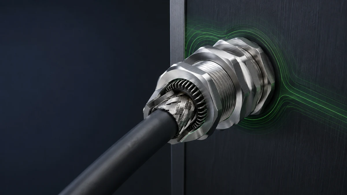
Cutaway illustration of a braided cable screen, surrounding contact and metal gland mounted through an enclosure panel.
Installation quality can reverse a design comparison
A good contact design can underperform if installed geometry differs from the test specimen. Strands may be cut, folded unevenly, or trapped outside the contact. Prepared diameter may fall outside the range.
Paint or anodising, an oxide surface treatment, can interrupt the panel connection. An adapter adds another joint to inspect. Use the product instructions to control preparation and tightening for each candidate:
- Identify the exact cable and screen layer to terminate.
- Record the screen preparation length and contact diameter allowed by the gland instructions.
- Keep braid coverage, strand condition and foil treatment consistent.
- Verify the contact element is seated around the intended circumference.
- Trace the body, adapter, washer, locknut and panel contact surfaces.
- Apply the exact assembly sequence and tightening instructions.
- Recheck after the environmental, vibration and reassembly conditions relevant to service.
Use added paste, foil, braid, or earth leads only where the cable and gland instructions define the complete arrangement. These additions can affect sealing, retention, corrosion, and radio-frequency (RF) geometry.
I check the intended protective-bond path alongside screen termination. The earthing and bonding guide explains the different current paths and acceptance checks.
Three application patterns for selecting the contact design
Braided VFD motor cable on a conductive cabinet
I compare spring, cone or collet contacts using the prepared braid diameter and the specified strip lengths. Keep the braid round and intact, and include any reducers, locknuts and EMC washers in the test assembly. Hold the cable, plate, preparation, tightening, fixture and frequency band constant while changing the contact design. Independently rebuild the specimens to see how strand placement and seating affect the result. If the cabinet instructions call for paint removal, define the exposed area and its corrosion protection before testing. Then repeat the relevant EMC check after the vibration or temperature cycling expected in service. The preferred design is the one that fits this braid and keeps a stable connection through the complete cabinet joint. Check sealing, retention and protective bonding on that same final arrangement.
Foil-screened instrumentation cable with a drain wire
I begin with the cable maker’s termination detail. Thin foil can tear or wrinkle when handled like woven braid. Choose the specified wrap, support sleeve, overbraid or other interface that presents a stable conductive surface to the contact. Keep the drain-wire route the same in each comparison. Where the equipment assigns the lead a low-frequency duty, preserve that purpose and the required connection. For higher-frequency screening, test the prepared cable, gland and panel over the required band. Include the actual support under the foil so the specimen shows how the interface behaves when assembled. A braid spring fitted around an unsupported foil layer is a different mechanical arrangement from the intended braid contact, even if both cable jackets fit the seal. Inspect the prepared layer after a controlled rebuild to locate tears or uneven seating.
Painted enclosure with an adapter or reducer
Here I inspect the route from the gland body to the enclosure before changing the screen contact. Follow each thread, washer, adapter, locknut and coated face in order. Define any permitted bare or treated seating surface and the corrosion protection around it. Compare candidates using the same plate material, thickness, hole, tightening and accessories. A change in the adapter or surface treatment changes the test assembly as well as the installation. After correcting the joint, repeat the same frequency measurement and inspect the seating. Add relevant environmental conditioning where moisture or vibration can change the connection in service. Recheck the affected seal and protective-bond path after the treatment. This sequence directs work to the panel interface when the cable contact already fits and is seated correctly.
Compare the frequency curves, specimen, and method
Transfer impedance and screening or coupling attenuation vary with frequency and depend on the specimen and method. IEC TS 62153-4-1:2014+AMD1:2020 CSV introduces screening measurements and their interpretation.
I choose the measured quantity and method before ranking designs. Transfer impedance relates a disturbance current on one side of a screen to the coupled voltage on the other under the defined method. Attenuation expresses a reduction relative to the method’s reference. Keep the exact quantity and units with each curve.
IEC 62153-4-7:2021+AMD1:2025 CSV addresses screened connectors and cable assemblies using the triaxial tube-in-tube method. IEC 62153-4-10:2015+AMD1:2020 CSV addresses feed-throughs and electromagnetic gaskets using a double-coaxial method. Both cover their specified transfer-impedance and attenuation measurements.
Choose the method whose test object and interfaces represent the comparison. Keep cable-assembly, feed-through and bare-contact measurements identified so a result from one boundary is not mistaken for the complete installed path.
When comparing two designs, align:
| Comparison field | Required match or disclosure |
|---|---|
| Device under test | Exact gland, size, cable, screen, panel, accessories and assembly state |
| Quantity and unit | Transfer impedance, screening attenuation or coupling attenuation; lumped or length-normalised |
| Method | Exact IEC part, edition, fixture and any deviations |
| Frequency range | Same points and valid fixture band; not one headline value |
| Preparation | Screen exposure, contact diameter, strand/foil treatment and tightening |
| Repeatability | Repeated sweeps and independently rebuilt specimens where assembly variation matters |
| Environment | Temperature, humidity, corrosion, vibration or cycling applied before or during measurement |
| Uncertainty | Measurement capability and decision rule for close results |
Worked example: a curve crossing changes the choice
Consider two hypothetical designs measured as lumped transfer impedance in the same suitable fixture with the same cable, panel and assembly conditions. The following values are assumed solely to explain how to read a comparison. They are not measurements of a Bepto product.
| Frequency | Design A | Design B | Lower transfer impedance |
|---|---|---|---|
| 10 MHz | 8 mΩ | 12 mΩ | A |
| 100 MHz | 30 mΩ | 18 mΩ | B |
At 10 MHz, A is lower by 4 mΩ; at 100 MHz, B is lower by 12 mΩ. If the important disturbance band includes 100 MHz, choosing A from the first row would miss its poorer result there. Two points illustrate the issue; the actual selection uses the full valid sweep, the required limits and the variation between samples. I inspect the bands where the curves cross, then check whether either candidate meets the requirement throughout. A design that looks attractive at one frequency may need a better panel joint or different contact preparation to meet the whole band. Rebuild the samples after that change and repeat the same comparison. This turns the curve into a guide to the next physical change rather than a single marketing number.
Account for uncertainty and assembly variation
Measurement uncertainty describes doubt associated with a measured value. Independently rebuilding specimens also reveals variation caused by screen preparation and seating. The NIST paper on conformity, decision rules and risk explains how uncertainty and the acceptance rule affect decisions. I agree that rule before testing, then apply it consistently to each candidate.
For close results, compare the difference with the measurement capability and assembly spread before declaring an advantage. Keep the curves and the affected band visible. The transfer-impedance interpretation guide explains units and method selection; the comparative test guide develops the matched A/B procedure.
Lower transfer impedance is favorable for the same tested boundary and definition. Screening or coupling attenuation needs its own sign convention: when reported as a positive attenuation amount, a larger value means greater reduction. I keep these quantities in separate comparisons and retain the fixture’s valid frequency range, so changing the result label cannot silently reverse the ranking.
Check the functions that share the selected entry
IEC 62444:2010 covers construction and performance requirements for complete glands as supplied. After selecting the contact, check the functions that share its cable and mounting arrangement. Seal fit depends on the jacket and insert; retention depends on the grip and cable; the panel joint depends on its thread, washer and seating surfaces.
I include ingress, retention, required protective bonding and environmental compatibility in the final selection. Where a hazardous-area approval is required, use the exact certified configuration and its installation conditions. A change to preparation, an adapter or a conductive washer can affect more than the screen path. Inspect those affected interfaces before accepting the revised installation.
Conclusion
For effective 360° EMC shielding, I select a contact that fits the actual screen and makes a short, stable route into the enclosure. Spring, cone and collet designs are useful candidates for supported braid; foil needs its specified contact arrangement. The practical preference is the design that an installer can assemble consistently on that cable and panel.
Compare the complete path across the required frequency band, including independently rebuilt samples. Use the result to identify a weak screen contact or panel joint, then confirm the correction with the same method. Finish by checking the sealing, retention and electrical functions that share the chosen entry.
FAQs about 360° EMC cable gland designs
Does 360-degree contact automatically provide better EMC shielding?
A short circumferential contact can reduce the detour in the screen-current path. Its performance also depends on the contacted layer, body joints and panel connection. Compare the complete arrangement across the required frequency band, with consistent screen preparation and assembly.
Is a spring-contact EMC gland always better than a cone-clamp design?
Choose between them by the prepared screen and assembly method. A spring needs a suitable diameter and seating range; a cone needs a controlled screen stack and compression. Compare repeatable assembly, environmental stability and matched frequency results for the intended cable.
Can an EMC cable gland terminate a foil screen directly?
Use the termination defined for the exact cable and gland. Thin foil may need a support sleeve, conductive wrap, braid or another specified interface. Identify the metal layer that the contact touches and preserve its connection through the body to the panel.
Does low DC resistance prove high-frequency shielding performance?
A DC measurement checks the conductive path near zero frequency. Use the applicable transfer-impedance or attenuation method for the required frequency band. Joint geometry, inductance, contact distribution and the test boundary influence that response alongside the DC connection.
Does an EMC test result also prove IP protection or protective bonding?
Check each required function with its applicable method on the intended configuration. EMC testing assesses the screening path; ingress checks assess sealing, and protective-bond checks assess the assigned protective connection. Keep cable preparation, accessories and panel details consistent across those assessments.
Sources and technical references
-
NASA, Effectiveness of Shield Termination Techniques Tested with TEM Cell and Bulk Current Injection, 2009, accessed 2026-10-28.
-
IEC TS 62153-4-1:2014+AMD1:2020 CSV - Introduction to electromagnetic screening measurements, accessed 2026-10-28.
-
IEC 62153-4-7:2021+AMD1:2025 CSV - Transfer impedance and screening or coupling attenuation of connectors and assemblies, accessed 2026-10-28.
-
IEC 62153-4-10:2015+AMD1:2020 CSV - Transfer impedance and screening attenuation of feed-throughs and electromagnetic gaskets, accessed 2026-10-28.
-
IEC 62444:2010 - Cable glands for electrical installations, accessed 2026-10-28.
-
Assessment of Conformity, Decision Rules and Risk Analysis - NIST, accessed 2026-10-28.