

Entry thread seals close the joint between a gland or adaptor and the enclosure wall. To maintain an IP rating, I specify that complete joint. I check the thread and shoulder, then seal geometry and the hole or tapped entry. Panel surface, installed layers and materials must match too. The tightening method and tested enclosure arrangement complete the review.
Key takeaways
- Locate the intended entry seal before selecting a washer, O-ring, gasket, or thread-sealing method.
- Keep the cable jacket seal and enclosure-wall seal as separate interfaces.
- Measure the gland entry, panel hole, shoulder, continuous sealing land, wall thickness, and usable thread.
- Match seal material to temperature, water, oils, cleaners, UV, ozone, cable jacket, and enclosure finish.
- Preserve the tested arrangement through correct parts, surface preparation, tightening and inspection.
Define what entry thread seals must close
The entry interface is where the gland or adaptor crosses the enclosure boundary. Water or dust may cross the shoulder or damaged seal land. It may follow a designated thread-sealing path or nearby opening.
I check that wall joint separately from the jacket seal, clamp, armour and screen contacts. Each has its own surfaces and function. A sound cable seal cannot establish that the wall opening is sealed.
IEC 62444:2010 covers complete-gland requirements and tests within its scope. IEC 60529 classifies enclosure protection. I link an IP claim with the tested cable, gland and entry seal. Accessories, hole or thread and enclosure must also match. I retain orientation, assembly and test conditions.
The IEC 60529 update guide explains how to keep the classification with the selected entry arrangement.
For example, a gland can seal correctly around its cable while water crosses an unsupported washer at the panel face. A different enclosure may have a dry shoulder joint yet leak through a damaged door gasket. Trace the observed path before changing the gland torque or seal material.
Match the seal to the entry arrangement
I distinguish three mountings: a parallel thread in a tapped entry, a tapered thread in a matching entry, and a parallel thread through a plain hole. Their retention and sealing geometry differ. I check the exact family, designation and pitch or threads per inch. Form, tolerance basis and usable engagement must also be identified.
IEC 60423:2007 specifies conduit and fitting thread dimensions within its cable-management scope. The PG, Metric, and NPT comparison helps keep these thread families separate.
A NIST study of pitch-diameter measurement illustrates why a thread cannot be identified from crest diameter alone. Use the product drawing and the specified functional gauges to confirm thread designation and fit; reserve calipers for the dimensions they can measure directly.
| Entry arrangement | Retention path | Seal fields to verify |
|---|---|---|
| Parallel thread through a plain hole | Locknut clamps the gland, panel, seal, and accessories | Hole size, shoulder overlap, flat land, seal ID and OD, wall thickness, washer stack, usable male thread |
| Parallel thread in a tapped wall or hub | Male thread engages the female entry | Shoulder or groove, face seal, usable depth, chamfer, runout, counterbore, thread identity |
| Tapered thread in a matching entry | Tapered thread develops the documented joint | Approved thread sealant or accessory, engagement method, thread condition, positioning rule |
| Adaptor or reducer assembly | Each male/female pair forms another retained interface | Every shoulder, seal, thread, material pair, accessory, and remaining usable length |
I read the gland, seal and enclosure drawings together to locate compression and its supporting surface. The O-ring-versus-washer guide explains the geometry and materials. For either seal, its dimensions and mounting need to match the IP-tested assembly.
Measure the hole, shoulder, and sealing land
Radial entry clearance is half the difference between the panel-hole diameter and the gland entry diameter. For measured hole diameter and the largest entry diameter that passes through it :
The shoulder must also overlap the opening. A preliminary radial overlap is:
Here, is the effective diameter supporting the seal. I use the drawing’s actual circular geometry. Slots, flats, notches and recessed holes need a direct profile check, as do curved walls and irregular openings.
A positive is only a starting dimension. The seal still needs the specified inside and outside diameters, position and continuous supporting land. The entry-hole sizing guide covers the cut-out and tool-access checks.
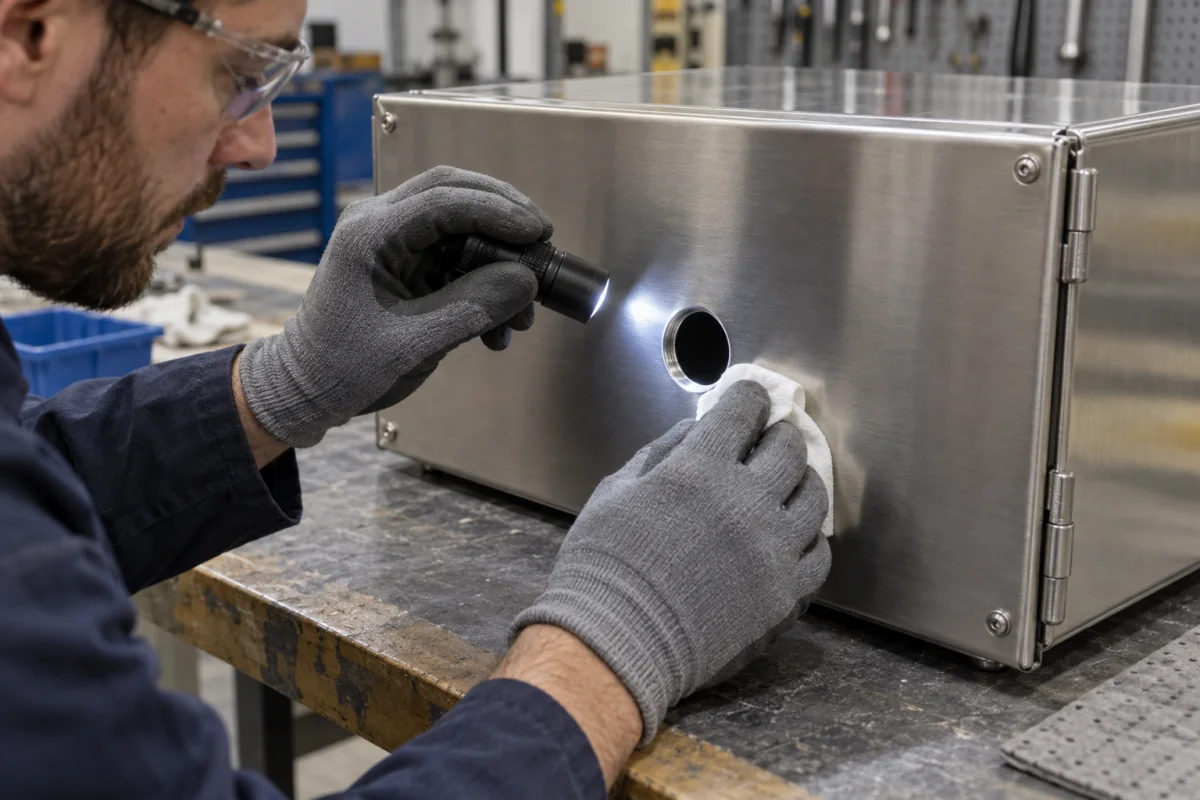
If a hole may be oval or distorted, I measure several directions. I record burr removal and cut-edge protection. I inspect the outer face for paint runs, weld spatter, steps and deep scratches. Mould texture, curvature and deformation may also affect support.
Apply hole and position tolerances before accepting shoulder and seal support. For example, a correctly sized hole near a fold may lack flat land on one side.
The product drawing defines the groove, shoulder, seal, thread and accessory geometry, including their tolerances and installed condition. The figure locates the supporting surfaces and layers to check; the final dimensions come from the selected assembly.
Check the installed axial stack
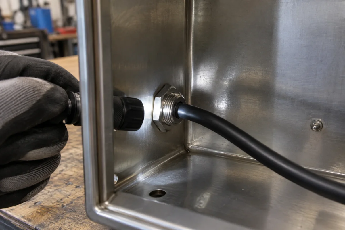
The installed axial stack is the set of layers using male thread from shoulder through required locknut engagement. For a plain hole, I list the panel and installed seal first. Then I add backing washer, earth tag, continuity washer and any adaptor shoulder. Required locknut engagement completes the length.
I use compressed dimensions where specified. I compare the complete tolerance stack with usable full-form thread—thread with complete geometry. Incomplete ends and the locking feature must be allowed for.
For a tapped entry, I compare usable male length with usable female depth. I exclude chamfers, incomplete threads and counterbores. Debris, coating, bottom clearance and internal obstructions can reduce the usable depth too.
The shoulder or face seal must reach its specified condition while engagement stays within the documented range. If orientation matters, follow the maker’s positioning method. Do not back off a completed sealed joint.
I calculate the worst case. A thicker panel, thicker seal and larger washer may occur with a shorter male thread. Usable length, required engagement and the controlling tolerance determine the remaining margin. This identifies whether a long-thread gland, permitted washer arrangement or revised panel is needed before assembly.
Select seal form and material from the joint
A flat sealing washer is a ring-shaped gasket compressed between the shoulder and supported enclosure land. I check its inside and outside diameters, thickness and installed thickness. Hardness, recovery and support matter too.
An O-ring face seal is an elastomer ring held in a designed groove or housing against a mating land. I check cross-section, groove depth and width first. Then I check stretch, groove fill, material and tolerances. Parker’s O-Ring Handbook gives general static face-seal guidance. The selected gland and seal drawings define the actual groove.

I choose the compound for the actual joint exposure. I record heat, water and humidity, followed by oils, fuels, cleaners, acids and alkalis. Ozone, UV, jacket contact and enclosure coating also matter. I include the expected service interval.
Check current compatibility data for the exact compound. NBR, EPDM, silicone and FKM are rubber-family labels covering many formulations. Storage age, assembly temperature and lubrication also follow maker requirements.
Install the entry seal without changing its design
Inspect the part number, dimensions, material, and condition before assembly. Clean the panel land and gland shoulder with a method compatible with the finish and seal. Remove burrs, chips, loose coating, and residue. Keep sharp male threads away from the sealing surface. Position the washer flat or seat the O-ring in its designed housing without twist, cuts, stretching, or trapped debris.
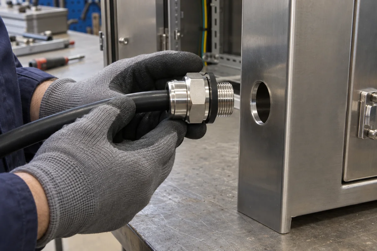
I start threads square by hand and keep the gland perpendicular to the panel. I counterhold the body feature named in the instruction. I tighten the locknut or entry to the stated torque, turns, shoulder, gap or other endpoint. Cable-seal tightening is a separate operation.
I then inspect seating and shoulder support, engagement and accessory order. Orientation and cable position must be correct. Any bonding or electromagnetic-compatibility (EMC) contact needs its own check.
If geometry conflicts, I resolve the drawing or parts choice. Extra washers, generic sealants and improvised spacers change engagement and the water path. They cannot establish overlap, repair damaged land or correct a short thread, wrong groove or distorted panel.
The temperature-cycling and venting guide helps if pressure breathing or condensation also affects the duty.
Separate the cable seal, entry seal, and other enclosure openings
After work, I inspect the whole enclosure. I include door or cover gaskets, unused openings, plugs and vents. Windows, fasteners, entries and cable support need checks too.
The gland, cable, seal, adaptor and locknut need to match the tested arrangement. Panel geometry, tightening condition and orientation affect the same enclosure boundary. The required inspection and ingress test assess the complete installed entry under its specified method.
After a failed test, I locate the route before changing torque or parts. Dry and inspect the enclosure, then find the first wet or contaminated area. I check the jacket seal and face joint first. Thread and adaptor joints, nearby openings, door gasket and pressure source follow separately.
Random tightening can hide the original route and damage a serviceable seal. A correction needs to address the identified water path.
Conclusion
Entry thread seals help maintain an enclosure IP arrangement when seal form, shoulder, hole or tapped entry, supported land, stack, material and assembly method agree. I would inspect the cable seal and enclosure-face seal separately rather than infer one from the other.
The opening, shoulder overlap, seal housing, material, engagement and accessory order determine whether the wall joint can seal. Tightening and enclosure test conditions also need to match that assembly. These checks connect the chosen washer or O-ring to the installed boundary rather than assuming that a thread alone stops water.
FAQs about entry thread seals and enclosure IP ratings
Does every threaded cable-gland entry need a separate washer or O-ring?
Use the sealing method specified for the exact gland and enclosure joint. Parallel entries often use a designed face seal. Tapered entries can use a documented thread-sealing method. Confirm the thread form, shoulder or groove, seal part, engagement, material, and installation instruction together.
Can an entry thread seal compensate for an oversized panel hole?
The gland drawing defines the accepted hole, shoulder, and seal support. Measure the hole and effective shoulder overlap across all tolerances. A seal needs a continuous supported land; replace or rework a panel detail that falls outside the specified geometry.
Can an entry thread seal be reused after gland removal?
Follow the seal and gland manufacturer’s service instruction. Inspect identity, cuts, set, distortion, swelling, hardening, contamination, and surface damage. Fit a new specified seal whenever the instruction calls for replacement or the existing part cannot meet its documented installed condition.
How do I confirm that an entry seal supports the enclosure IP rating?
Match the installed cable, gland, seal, accessories, opening, enclosure, orientation, assembly method, and tightening condition to the relevant test record. Then complete the project’s final inspection or ingress test on the assembled enclosure.
Sources and technical references
- IEC 62444:2010, Cable glands for electrical installations, accessed 2026-09-12.
- IEC 60529:1989+A1:1999+A2:2013, Degrees of protection provided by enclosures, accessed 2026-09-12.
- IEC 60423:2007, Conduit systems for cable management - Outside diameters and threads, accessed 2026-09-12.
- Parker Hannifin, O-Ring Handbook (ORD 5700), accessed 2026-09-25.
- NIST, Pitch Diameter Measurement of Threaded Gages Using the CMM, accessed 2026-09-12.