

The most reliable anti-vibration locking mechanisms are the ones matched to the moving joint, its reaction surface and the required maintenance method. I start by locating the rotation: a closing nut, gland body, panel locknut or adapter can each need a different solution. A well-chosen lock then preserves the seal, cable grip and assigned electrical connection while the assembly is vibrating.
For a designed panel cutout, a key or tab can provide a clear mechanical stop. For a suitable threaded joint, a permitted prevailing-torque feature or specified threadlocking compound may be practical. A matched washer system needs compatible bearing faces and enough thread length. The sections below explain how I narrow those choices and compare the finished assemblies.
Key takeaways
- Locate the rotating joint before choosing its locking feature.
- Select the reaction surface, thread engagement and service access with the lock.
- Check seating and clamp load as well as visible rotation.
- Preserve the separate cable seal, panel seal, retention and electrical duties.
- Compare candidates with the same panel, supported cable and vibration input.
Locate the joint and the motion that loads it
A gland contains several threaded or clamped interfaces. The closing nut, also called a compression nut, operates the cable-side seal or grip. The body provides the main structure and enclosure connection. A locknut can hold the body through a clearance hole, while an adapter adds another connection between threaded parts.
I mark those contacts on the assembly drawing, then follow the load into them. Motion of the enclosure panel can load the body connection. A long unsupported cable can bend or twist the entry. Tightening the closing nut can also turn the body if it is not held at the specified flats.
| Joint | Motion to investigate | Functions to preserve |
|---|---|---|
| Closing nut to body | Nut rotation, changing closure position, cable-driven twist | Cable seal, grip and any operated clamp |
| Body to tapped enclosure | Body rotation or lifting from its seat | Entry seal, usable engagement and assigned bonding |
| Body through a plain hole | Locknut or body movement against the panel | Wall sealing, clamp seating and local panel strength |
| Adapter or reducer | Relative motion at either threaded end | Alignment, engagement, sealing and electrical path |
The high-vibration selection guide connects equipment motion with cable support and panel response. I use that information to decide whether the problem calls for a lock, a support change, a stiffer mounting arrangement or a combination of them.
Why can a tightened entry still move?
Preload is the axial force established by tightening a joint designed to carry that load. Friction at its threads and bearing surfaces helps resist movement. Relative motion, a loss of seating or a change in the clamped stack can reduce that resistance. The NASA Fastener Design Manual, published in 1990, explains these relationships and the roles of locking methods, washers, lubrication and torque.
Three mechanisms deserve separate checks:
- Rotational loosening: one threaded part turns relative to its mate.
- Settlement or deformation: the bearing stack changes thickness or shape, reducing clamp force even with little visible turn.
- Cable or panel loading: the surrounding structure repeatedly bends, twists or displaces the connection.
For example, an aligned paint mark can remain visible while a soft washer or polymer panel settles. A stronger rotational lock would leave that seating issue unresolved. I inspect the bearing surfaces and seal condition as well as the marked position.
Temperature cycles, corrosion and polymer creep can change the joint between vibration events. Creep is gradual deformation under sustained load. A test on a rigid new plate therefore needs a different interpretation from service on a flexible wall with an aged seal and a moving cable span.
Compare anti-vibration locking mechanisms by their contact
An anti-rotation feature resists relative turning at a defined contact. Some methods rely on thread interference or cured material; others transfer motion into a key, tooth or matched bearing surface. I choose among them by the interface available and the conditions needed to assemble and maintain it.
| Mechanism | How it acts | A useful application | Selection checks |
|---|---|---|---|
| Specified threadlocking compound | Cured material resists movement in mating threads | A permitted body-entry or adapter thread | Material compatibility, preparation, amount, cure and removal |
| Prevailing-torque nut or thread | Deliberate interference resists turning | A designed locknut or integrated thread feature | Correct mate, full engagement, temperature and reuse conditions |
| Serrated bearing feature | Teeth react against the mating surface | A panel joint designed for that contact | Panel hardness, coating, sealing land and corrosion protection |
| Tab or keyed geometry | A positive feature transfers rotation into a mating stop | A matching body/cutout or tabbed accessory | Orientation, edge strength, clearance and local wall loading |
| Matched cam or wedge washer pair | Its cam geometry opposes loosening at the bearing interface | An explicitly specified washer arrangement | Pair orientation, bearing faces, stack height and engagement |
| Captive or integrated lock | A supplied feature constrains movement at its designed joint | A gland assembly with defined closing and release steps | Feature engagement, inspection, reset and service procedure |
The table narrows the candidates; the mounted comparison resolves which one retains the required functions. A permitted compound may be convenient at a rarely disturbed adapter. A mechanical feature with a visible engagement point may suit a serviceable panel entry. Both choices still depend on the actual gland, mounting and operating conditions.
Distinguish a spring washer from a locking system
A washer can spread load, seal a face, act as a spring or provide a defined locking action. Those are different jobs. The NASA manual explains that a typical helical spring lockwasher becomes flat under normal tightening and then behaves like a flat washer. I therefore identify the washer’s working feature before including it as the anti-rotation method.
A sealing washer remains part of the water boundary even when another accessory handles locking. Preserve its specified location and contact surfaces. Removing it to make space for a locking washer changes the entry’s sealing arrangement.
Choose threadlocking compound with the installation process
A threadlocking compound needs a compatible joint and a controlled application. I check the named product against the gland and enclosure instructions, then define the contacted materials, surface condition, application area, quantity, cure conditions and removal method. Cure is the process by which the material hardens into its working state.
NASA’s 2011 characterization of Loctite 242 and 271 examined those materials as secondary locking features for space-station fasteners. It illustrates why installation conditions belong in an assessment of a locking compound. For a cable entry, use the current instructions for the selected compound and the actual joint rather than copying that fastener configuration.
Keep the compound at the intended contact
Compound applied to an entry thread acts at that thread. The cable-side closing nut remains a separate connection. Prevent excess material from reaching the cable seal, jacket, armour clamp or screen contact. The screen is a conductive cable layer used for electromagnetic screening.
A compound can also change friction during assembly. Match the tightening method to the specified treated condition; changing a dry joint to a coated one changes an input to the torque process. The lubricants and compounds guide develops those material and contact checks.
Plan removal before selecting the grade
Consider tool access, allowable heating, nearby polymers and the frequency of disassembly. A service procedure that requires repeated opening can favour a reusable mechanical feature or a compound intended for that removal cycle. If the installation cannot provide the required preparation or curing conditions, choose a method whose assembly process can be carried out consistently there.
Match panel-side locks to the wall and seal stack
A through-hole gland transfers clamp load through its shoulder, seals, washers, panel and locknut. The panel is a working part of that connection. A thin polymer wall, coated sheet and rigid bare-metal plate give a serration or key different contact conditions.
I check the reaction surface before choosing teeth or a tab. Serrations can damage a coating or soft wall; a key concentrates load at its mating edge. A sealing land needs the contact finish and geometry required by its seal. The selected stack must also preserve any assigned electrical bonding path and the corrosion protection of exposed surfaces.

Check the thread space consumed by an added accessory
Use the minimum available full-thread length, excluding incomplete end threads and runout. Compare it with the largest applicable wall, compressed seal and washer thicknesses, plus the drawing’s required locknut engagement. This checks geometry; the joint design also needs adequate material strength and bearing support.
Consider a hypothetical mounting stack with 9.0 mm of usable male thread, a 3.0 mm panel, a 1.0 mm compressed seal and 4.0 mm required locknut engagement. The reserve is 1.0 mm. Adding a 1.5 mm accessory changes that reserve to −0.5 mm. I would select a suitable longer-thread variant or a different permitted locking arrangement, then check the resulting inside projection and access. The assumed 4.0 mm engagement is a drawing input for this example.
Make an integrated feature easy to inspect
A keyed cutout needs the specified shape and enough surrounding panel material. A tab needs its mating feature and correct orientation. A captive part needs a defined engaged position and release procedure. I include those details in the maintenance record so a visually similar ordinary accessory does not replace a working lock.
Check the joint that each feature actually restrains. A keyed body holds its panel orientation; the closing nut still needs its own correct assembly. The sealing and strain-relief guide explains the cable-side functions that must remain intact.
Establish seating before judging the lock
Start with sound threads, correct mating parts and clean, suitable bearing surfaces. Follow the prescribed closing sequence, holding the body where instructed while turning the designated nut. This establishes the intended seat without using the cable or another gland joint as the reaction point.
Torque relates to preload through thread and bearing friction, geometry and material behaviour. I use the gland’s stated assembly method, including any compound or lubrication condition. The gland torque guide explains why the part being turned and the part being held matter.
Record reference positions at the relevant joints after assembly. A witness mark shows visible relative rotation between marked parts. Combine it with checks of closure position, seating and required functions. A later breakaway torque measures the effort needed to start movement; cured compound, prevailing torque and changed friction can all contribute to that reading.
For an installed entry, inspect safely with the equipment isolated where electrical hazards require it. Adjustments and measurements should follow the equipment and gland procedures. A useful maintenance action addresses the observed cause: damaged bearing surfaces, a displaced seal, insufficient engagement or an incorrectly assembled locking feature.
Compare candidates under the same vibration conditions
Representative vibration testing reproduces the relevant mounting and loading conditions closely enough to answer the design question. Define the panel, fixture, cable support and free span—the unsupported cable length—as well as the applied motion. These details determine how the input reaches the gland.
A NASA-sponsored 1995 single-bolt study used controlled random vibration and varied preload, locking device, joint configuration, fit and attached mass. Its comparison approach is useful here: hold the application conditions constant while assessing the intended locking change. Its bolt results remain results for those tested joints.
IEC 60068-2-6:2007 provides a sinusoidal-vibration test procedure at specified severities. Use the relevant equipment or project requirement for the profile and acceptance criteria. A sine sweep varies frequency through a range; a dwell holds an input condition for a specified time. Random motion and shock need the applicable procedures for those exposures.
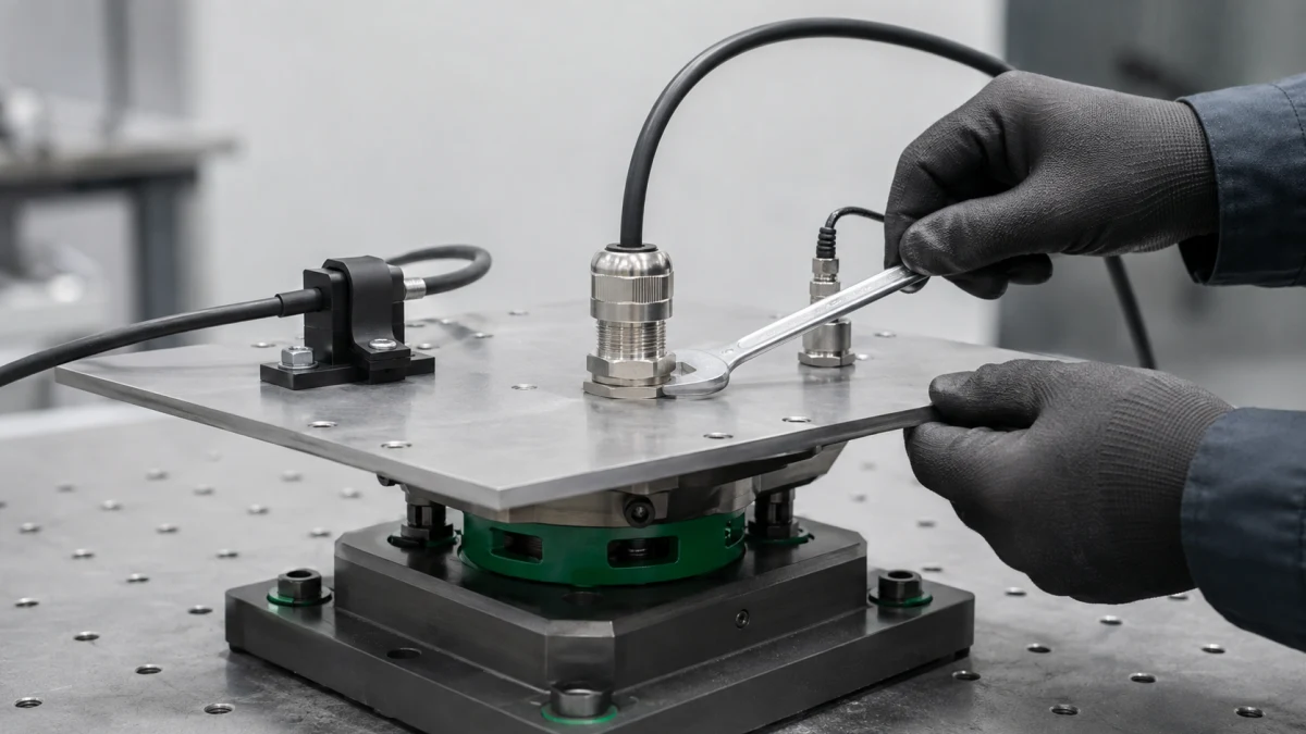

I define the comparison in three stages:
- Before exposure: record exact parts, preparation, closure, seating, cable position and required baseline functions.
- During exposure: apply the specified axes, frequency content, displacement or acceleration, duration and operating states. Measure the input at the relevant mounting location.
- After exposure: compare each joint’s position, inspect damage and repeat the functions the motion could affect.
| Observation | What it indicates | Follow-up |
|---|---|---|
| Closing-nut mark moves | Relative turn at the cable-side joint | Check closure, cable seal and retention |
| Body or locknut moves | Change at the panel mounting | Check seating, engagement, entry seal and electrical path |
| Marks align but stack settles | Possible clamp-load loss without clear rotation | Inspect bearing materials and use the specified load/seating assessment |
| Cable moves in the entry | Changed retention or imposed cable load | Check grip, jacket condition and external support |
| Water path appears after conditioning | A disturbed sealing interface | Locate the path and inspect the corresponding contact |
IEC 62444:2010 addresses construction and performance requirements for complete glands as supplied. Keep the relevant complete-gland checks beside the vibration assessment. The pull-out strength guide covers the gland-and-cable retention comparison.
Choose from the surviving arrangements
I make the final choice in the order the joint works: locate the motion, select a compatible reaction method, establish the correct assembly and compare retained functions after the required exposure. Include service access and replacement parts in that decision, because the same locking action must be restored after maintenance.
For example, a keyed body is a useful candidate when the enclosure drawing already provides the matching cutout and edge strength. On a plain-hole panel, a permitted locknut system may fit the existing interface more directly. At an adapter that is rarely disturbed, an approved compound process may suit the available space. Confirm each candidate on the actual mounting stack and supported cable before fixing the production arrangement.
Conclusion
Reliable locking starts at the joint that can turn. I compare compound, prevailing-torque, keyed, serrated and integrated methods by the contact they use, the assembly process they need and the functions they must preserve.
Check usable thread and panel seating before adding an accessory. Then assess rotation, seating, cable retention, sealing and the required electrical paths under the same vibration conditions. That gives the selection a clear connection to the installed entry and its maintenance needs.
FAQs about cable gland anti-vibration locking
How should I compare threadlocking compound with a mechanical locknut?
Compare the joint each method secures, its materials and reaction surfaces, the assembly controls and the removal process. Use permitted configurations with the same gland, panel, cable support and vibration input. Select the arrangement that retains the required functions and can be maintained consistently.
What should I check before adding a serrated locknut?
Check the permitted bearing surface, panel strength, coating and corrosion protection, seal position and electrical path. Include the locknut and any accessories in the full-thread stack calculation. Follow the component order and tightening method for the selected gland and enclosure.
What can a witness mark tell me after vibration?
It shows visible relative rotation at the marked joint. Inspect seating, seal condition and cable position alongside it, because the bearing stack can settle without an obvious turn. Use direct load measurements where the test plan requires them.
Which vibration conditions belong in the comparison?
Use the equipment or project requirement at the gland mounting location. Define axes, frequency content, displacement or acceleration, duration, shocks and operating states. Keep the panel, fixture, cable support and free span consistent between candidates.
When is a threadlocking compound a suitable choice?
It is a candidate when the gland and enclosure instructions permit the selected compound at that thread and the required preparation, cure and removal process are practical. Check all contacted materials and its effect on tightening, sealing and assigned electrical connections.
Sources and technical references
- NASA, Fastener Design Manual, 1990, accessed 2026-10-29.
- NASA, Performance Characterization of Loctite 242 and 271, 2011, accessed 2026-10-29.
- NASA, Experimental Analysis of Thread Movement in Bolted Connections Due to Vibrations, 1995, accessed 2026-10-29.
- IEC 60068-2-6:2007, Sinusoidal vibration testing, accessed 2026-10-29.
- IEC 62444:2010, Cable glands for electrical installations, accessed 2026-10-29.