

MC4 branch connectors join the positive conductors from compatible photovoltaic strings together and join their negative conductors through a separate branch. I would begin by tracing the current through both branches. Check system voltage, polarity, cable, protection and the identified connector system before choosing the parts. A branch does not make arbitrary 4 mm PV connectors compatible, choose overcurrent protection for you, or increase another component’s rating. Its certification must cover the assembly you plan to use.
Key takeaways
- Parallel strings keep a common operating voltage while their currents combine in the branch output.
- Check the branch connector, output cable, downstream terminals, and protection against the combined current, not one string’s current.
- Treat “MC4” as a specific connector-system name, not a universal compatibility standard for visually similar 4 mm PV connectors.
- Use matched connector halves from the same identified system unless an exact certified combination explicitly permits otherwise.
- Never use a PV connector without breaking capacity as a load-break switch; isolate and verify the circuit before unlatching it.
What are MC4 branch connectors, and what are they not?
An MC4 branch connector joins same-polarity conductors from two or more PV strings into one output path. A matching positive and negative branch keeps the polarities separate. Port count describes the circuit layout; it does not establish current, voltage, cable size, environmental rating, mating system, or certification.
Cross-mating connects a plug and socket from different manufacturers or systems. “MC4” does not establish compatibility for every similar-looking 4 mm PV connector. The NLR standardized PV connector nomenclature record explains errors caused by “MC4 compatible,” cross-mating, and male/female labels.
Polarity and both mating part numbers identify the connection more reliably than shell appearance. Contacts, seals, conductor range, cable outside diameter and tooling must also suit the same connector system; a pair that latches can still be an unsuitable combination.
The connector terminology section helps keep plug, socket, positive, negative, contact, and seal labels consistent between the circuit drawing and installation record. Terminology cannot prove compatibility, but it can prevent a physical half, circuit polarity, or mating claim from being misidentified.
The IEC 62852:2014+A1:2020 consolidated version covers connectors for DC photovoltaic circuits. Its scope includes connectors that may be engaged or disengaged under voltage but have no breaking capacity. They are not automatically switches that can interrupt load current.
Use the documented current, voltage, cable, mating, temperature, and installation conditions. Do not open a connector under load unless the system is designed and approved for that duty.
What changes electrically when PV strings are connected in parallel?
A parallel PV string is one of several series-connected module strings joined across common positive and negative nodes. Parallel strings share operating voltage, while their currents combine in the output. A two-input branch does not double string voltage. It joins two positives in one branch and two negatives in the paired branch.
Count the strings feeding each output. Set maximum design current by the governing method, then check every component in series after that junction. The IEC 62548-1:2023+A1:2025 array-design scope covers DC wiring, protection devices, switching, and earthing. A branch connector cannot replace checks on output conductors, protection, disconnects, inverter inputs, or combiners.
For a branch output fed by strings, first calculate the unadjusted current sum:
Here, is the design current assigned to string , and is the sum entering the common output path. For three equal strings with design current , the sum is . This topology result is not the final cable or OCPD rating. Apply the governing array-design method and required environmental or installation factors, then compare the resulting duty with the connector, output cable, terminals, protection, and equipment input.
For a three-string branch, I would separate the review into four steps.
First, draw each positive and negative source and mark the common nodes. Identify the branch and output components. This is the circuit topology: it shows where the currents combine.
Then use the project design method to set branch count, maximum current and voltage, reverse-current protection, and the location of any overcurrent protective device (OCPD). Check the downstream equipment limits too. This establishes the electrical duty.
Follow the adjusted combined current through the output contact, conductor, terminal, disconnect, protective device and equipment input. Check every mating pair against the connector-system record. These records establish ratings and compatibility.
Finally, follow the assembly instructions for the contact, seal, conductor range, cable diameter, tooling and locking method. These control how you build the selected assembly.
I would check the string design before connecting branches, even if the housings fit. Confirm polarity, module count, open-circuit voltage behavior and operating voltage range. Check orientation or the maximum power point tracking (MPPT) arrangement where relevant, along with the equipment manufacturer’s input rules. Mismatched source characteristics can cause circulating or reverse current and shift the operating point. A branch cannot correct those differences.

Follow each red and black cable from its source box through the assigned branch and output. I would then compare the number of ports, common nodes and destinations with the controlled circuit drawing. Use the approved design, part records and required tests to establish polarity, conductor duty, OCPD selection, connector compatibility and electrical status.
Where must combined current and reverse current be checked?
The combined-current check begins at the internal branch junction and continues through the output contact, output conductor, any subsequent branch, combiner terminal, disconnect, protective device, and inverter or other power-conversion input. Each item needs a rating for the actual DC duty and installation conditions. Do not approve a 2-to-1, 3-to-1, or 4-to-1 layout from the number of ports alone.
| Design point | Required evidence | Common wrong shortcut |
|---|---|---|
| Each source string | Design current, conductor rating, module maximum series-fuse or reverse-current limit | Using nameplate operating current alone. |
| Branch connector | Exact model, contact and cable combination, rated DC current and voltage, temperature limits | Assuming every port carries only one-string current. |
| Combined output conductor | Conductor cross-section, insulation, cable OD, installation method, grouping and temperature factors | Reusing the source-string cable choice without checking combined duty. |
| Downstream equipment | Terminal and input limits, permitted string count, MPPT arrangement, polarity | Treating a connector as an input expander. |
| Reverse-current protection | Fault-current sources, module limit, OCPD need, rating, location and interrupting duty | Assuming a branch connector provides protection. |
| Isolation | DC disconnecting method and verified de-energized state | Pulling the connector apart to interrupt load current. |
Reverse current flows into a source circuit from other parallel sources or connected equipment. Assess it before choosing string protection. The need, rating, and location of an overcurrent protective device depend on the sources, module limits, conductor ampacity, and available fault current. Ampacity is the conductor’s permitted current under its installation conditions. Local rules and equipment instructions also apply.
IEC 62548-1 treats electrical protection as part of array design. An unprotected branch housing provides no fuse, disconnect, reverse-current blocking or arc-fault protection. Use it for one of those jobs only if the component is separately certified for that function.
System voltage needs its own check. Parallel connection does not add string voltages, but the branch still sees the maximum possible DC voltage. Two parallel strings remain subject to the same cold-condition voltage review as the contributing strings.
Use the design standard and module data to establish maximum voltage, transients, and equipment limits. Compare those with the branch assembly and mating parts. Passing the current check does not resolve an inadequate voltage rating.
Why is cross-mating a separate compatibility decision?
Housings can latch despite differences in contacts, tolerances, spring force, seals, cable grips, tools, and test scope. Physical fit does not establish electrical or certified compatibility.
NLR’s Creating a Universal PV Plug and Socket Standard describes IEC 62852 and UL 6703 qualification as intended for the same manufacturer’s connectors and proscribing cross-manufacturer mating. Use the same identified system across modules, extensions, branches, combiner tails, and equipment leads.
For a proposed mixed pair, require evidence naming both halves and the certified combination. “MC4 compatible,” shared pin diameter, hand fit, and a generic standard reference are insufficient. A documented adapter harness may help, but check every added termination.
For a US project, I would first identify the adopted electrical code edition and equipment instructions. Establish the certification route and authority having jurisdiction—the body responsible for accepting the installation. “UL” alone does not answer these questions. The official NFPA 70 National Electrical Code page provides access to the code; it is not a branch-connector certification record.
In the responsible certification body’s current database, find the product category, file and model. Confirm the cable combination, ratings and permitted mating parts. A marketplace logo, supplier statement or listing for a similar family does not cover the assembly being supplied.
The Global Market Access guide can help separate a destination standard, certification scheme, and market rule before the exact connector-system record is checked in the responsible database. It does not replace that controlled certification record.
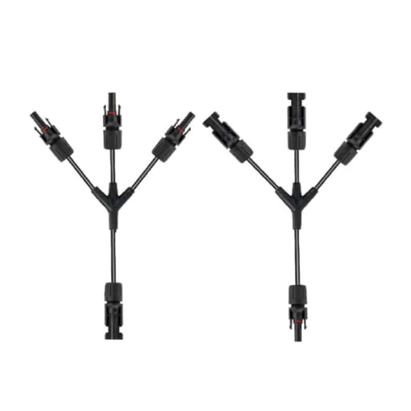
Identify the exact part numbers, mating system, current and voltage ratings, cable range, ingress rating, and certificate record before using this exterior form in a design.
Branch topology and connector-system selection
I would define the array circuit before selecting its branches. A compact Y-branch may suit a small number of matched strings feeding an input that permits them. A combiner or wiring harness may suit the design better when it needs individual string fuses, monitoring, isolation, surge protection, service access, cable transitions or many parallel sources. Let those needs determine the connector count.
Use this order:
- Define the electrical node. Identify which strings share one MPPT or DC input and confirm that the equipment permits the proposed parallel connection.
- Fix polarity and branch count. Draw positive and negative paths separately, including every intermediate branch and adapter.
- Establish maximum voltage and design current. Include environmental corrections and the applicable array-design method rather than informal safety factors.
- Resolve reverse-current protection. Compare available reverse current with module, cable, connector, and equipment limits; select OCPD only under the governing design rules.
- Choose one connector system. Record manufacturer, family, positive and negative part numbers, contacts, seals, cable range, and approved mating combinations.
- Match the cable. Check conductor material and cross-section, cable OD, insulation, temperature duty, routing, bend control, and strain at every connector entry.
- Check installation and certification evidence. Confirm tools, strip length, crimp dies, assembly torque or engagement method, locking indication, release method, environmental conditions, and exact certificate scope.
Use the governing PV array design method, module data, equipment instructions, and jurisdictional requirements to coordinate string current, reverse current, OCPD, and maximum voltage. Treat bend-radius and voltage-drop calculations as separate cable checks.
Installation and field inspection checks
During installation, keep the identified connector system and follow its documented assembly process. I would check part identity, cable preparation, contact crimping, full mating and locking, then review strain relief, routing, support, protection and isolation. A neat exterior cannot show that the right crimp die was used or that both latched halves belong to the same system.

I would use this fixture to check the support under each branch body and the straight cable section at every entry. Check clip positions, bend allowance, clearance from frame edges and access as well. Then use the specified instructions, inspection method and project records to resolve mating parts, engagement, crimp records, pull and environmental requirements, and electrical status.
The NLR study record for Photovoltaic Cable Connectors: A Comparative Assessment of the Present State of the Industry describes field and accelerated-test specimens examined with photography, resistance-current scans, X-ray computed tomography, cross-sectioning, microscopy, and materials analysis. That work shows why a visual check is useful but incomplete. Field acceptance should combine visual condition with traceable parts, assembly records, suitable electrical tests, and the exact manufacturer’s instructions.
Before energization, verify every source and combined-output polarity against the drawing. Check full engagement and locking, and handle unused ports as instructed.
Support cables without pulling or twisting branches. Keep assemblies out of standing water and away from damaging edges. Routing must also keep movement, abrasion, contamination, and heat within documented limits.
For maintenance, use the intended DC disconnecting means and site safe-work procedure. Verify the required electrical state before releasing a connector with its specified tool. An open AC disconnect does not remove the sunlight-driven DC hazard.
Apply the engineer’s and manufacturer’s rejection criteria to cracked, discoloured, deformed, contaminated, partly latched, or unidentified parts. Clean, re-crimp, reuse, or substitute contacts only where the instructions permit it.
The Cable Entry Glossary distinguishes plug, socket, positive, negative, crimp contact, locking parts and cable seal terminology. Clear terms help you identify the failed interface during troubleshooting: a polarity error, damaged seal and poor crimp need different corrections, even when the housings look similar.
Conclusion
Parallel PV strings operate at a common voltage, and their currents combine at the branch output. I would calculate the combined duty first, then check every downstream connector contact, output cable, terminal, protective device, disconnect and equipment input. Use the governing design method and actual installation conditions for that review. The branch housing does not provide reverse-current protection or raise another component’s rating.
Choose one identified, certified connector system for the branch and its mating halves. A named mixed combination needs explicit permission in the exact certification. I would then follow the instructions for cable, contacts, tools, polarity, locking, routing and isolation. A connector can fit without being compatible. Confirm the current path and assembly records before accepting a neat-looking installation.
FAQs: MC4 branch connectors
Can I mix MC4-style branch connectors from different manufacturers?
Do not mix them based on appearance or an “MC4 compatible” claim. Use the same identified connector system and approved mating parts. A mixed pair is acceptable only when current evidence explicitly identifies both halves and the certified combination for the required cable, ratings, and conditions. Physical engagement alone is not compatibility evidence.
Does a 2-to-1 Y-connector double PV string voltage?
No. A correct parallel connection places like polarities at a common voltage while combining current in the output path. The maximum circuit voltage still needs a cold-condition design check, and the output branch, cable, terminals, and equipment must be rated for the combined current and actual DC voltage.
Does every parallel string need a fuse?
Not automatically, and the branch connector cannot answer the question. Determine protection from the number and characteristics of parallel sources, possible reverse current, module limits, cable ampacity, connector and equipment ratings, the applicable array standard, equipment instructions, and local electrical rules. Document both the need and the location of any OCPD.
Can I disconnect a branch connector while the PV strings are producing current?
Do not use a connector without breaking capacity as a load-break device. Follow the system’s isolation and electrical safe-work procedure, operate the intended disconnecting means, and verify the required state before release. Use the specified unlocking tool and never rely on an AC-side switch to de-energize sunlit DC strings.
How do I calculate current in an MC4 branch output?
Add the design currents of all strings feeding the output. Apply the adjustments required by the governing PV array method and installation conditions. Compare the resulting duty with the branch connector, output cable, downstream terminals, protection, disconnect, and equipment input. Do not multiply string voltage when the strings are connected in parallel.
Sources and technical references
- IEC 62852:2014+A1:2020 consolidated version - Connectors for DC application in photovoltaic systems, accessed 2026-09-23.
- IEC 62548-1:2023+A1:2025 consolidated version - Photovoltaic array design requirements, accessed 2026-09-23.
- National Laboratory of the Rockies - Standardized Nomenclature for Photovoltaic Connectors, accessed 2026-09-23.
- National Laboratory of the Rockies - Creating a Universal PV Plug and Socket Standard, accessed 2026-09-23.
- National Laboratory of the Rockies - Photovoltaic Cable Connectors: A Comparative Assessment of the Present State of the Industry, accessed 2026-09-23.
- NFPA - NFPA 70, National Electrical Code, accessed 2026-09-23.