

Compare metal cable gland tensile strength by the grade, component geometry and installed load path. A higher-strength stainless grade can help when a thin metal section governs the design. Brass remains a candidate where its specified properties and machined sections meet the load, while aluminum can be useful when moving mass also matters.
I compare yield strength and ductility first, then follow the load from the cable contact to the enclosure. This identifies whether changing the metal will improve the assembly or whether the cable grip, threads or panel need attention instead.
Key takeaways
- Compare exact alloy, product form, supplied condition and test temperature on a common basis.
- Use yield strength for permanent-deformation checks, UTS for the specimen’s peak engineering stress, and ductility for deformation before fracture.
- Check thin sections and thread roots with their actual dimensions and load direction.
- Follow force through the cable contact, cap, body, entry thread and enclosure mounting.
- Choose the complete gland for its required retention, sealing, corrosion exposure and installation conditions.
How to compare metal cable gland tensile strength
Start with the load the gland must carry. Does it hold the cable, or seal a cable with separate support? Steady pull, cable weight, shock, movement and heat present different demands. The load passes through the cable contact, cap, body, thread, locknut and enclosure wall, so any of those interfaces can limit the assembly.
The alloy, thinnest section and joint geometry affect where each part may fail. For a useful strength comparison, keep product form, material condition, test method and temperature explicit alongside each grade. The gland also needs to suit its cable, accessories and mounting: the strongest material specimen may still be unsuitable because of corrosion, mass, bonding, sealing or installation requirements.
Relate tensile properties to the finished gland
Tensile strength, or ultimate tensile strength (UTS), is the maximum engineering stress reached by a defined specimen in a tensile test. Engineering stress relates force to the specimen’s original cross-sectional area. Yield strength marks the specified response indicating the onset of permanent deformation.
Ductility describes a material’s ability to undergo plastic deformation before fracture. Elongation is one way to measure its tensile response over a stated gauge length. The gauge length is the initial distance between the measurement marks. I keep strength and ductility separate because they answer different questions.
ASTM E8/E8M covers room-temperature metal tension tests for yield strength, tensile strength, elongation, and reduction of area. Reduction of area describes the cross-section’s decrease measured after fracture. Results apply to that specimen and condition. A gland adds machined sections, thread roots, cable contacts, and mating parts. Its capacity depends on their geometry and assembly.
| Engineering input | What it describes | How I use it in a gland comparison |
|---|---|---|
| Yield strength for an exact grade and condition | The stress at a specified permanent-deformation response | Assess loaded metal sections using their geometry and the applicable design criterion |
| Ultimate tensile strength for that specimen | Maximum engineering stress reached in the tensile test | Compare material rupture behavior alongside the component failure modes |
| Elongation and reduction of area | Deformation measured after rupture under the method | Compare ductility in the supplied and exposed conditions |
| Complete-gland retention result | Response of the tested gland, cable and mounting | Check the intended cable size, accessories, temperature and assembly method |
MPa means megapascals, a stress unit. For a uniformly loaded axial section, nominal stress relates force to its net area. In a gland, the bore and thread roots reduce that area, while the joint geometry can concentrate stress. Neck thickness, thread overlap, machining condition, and eccentric loading can alter capacity even in the same alloy. Eccentric loading applies force away from the section’s central axis.
Elastic recovery, permanent set and fracture
Elastic deformation is recovered when the load is removed. Plastic deformation leaves a permanent change of shape. A tensile specimen can show both: unloading recovers its elastic extension while some extension remains. Fracture is the final separation of the specimen, and the amount of prior plastic deformation can vary greatly. These distinctions follow the DOE materials handbook’s strain and ductility explanations.
In a gland, permanent set can alter thread fit, clamp contact or seal compression before a metal part breaks. I check the deformation limit as well as the rupture condition. Keeping the joint within its specified working limits preserves the seating and compression needed by the seal.
Read elongation and reduction of area with their conditions
For an after-fracture measurement, elongation compares the final gauge length with the original one. Reduction of area compares the original cross-section with the smallest final section at the fracture. The DOE handbook’s measurement diagrams distinguish the two geometries:
Here and are the original and final gauge lengths, while and are the original and minimum final areas. Use matching length units and matching area units. For a hypothetical specimen, a 50 mm gauge length that becomes 60 mm gives 20% elongation. A 20 mm² section that reduces to 12 mm² gives 40% reduction of area. The first measurement describes extension over the marked length; the second describes local contraction at the fracture. I retain both because necking concentrates deformation in a small part of the specimen.
Read the test report beside the percentage. Record the specimen shape and size, gauge length, sampling direction, strain or test speed, temperature, environment and material condition. Also retain the method used to identify the end of the test. A NIST study of tensile testing in hydrogen shows why the reported elongation can depend on that choice. Its reduction-of-area discussion also examines the difficulty of measuring a non-circular fractured section. Keeping those measurement choices consistent makes a change in ductility easier to interpret between material conditions.
Why alloy and condition matter
The alloy, product form and supplied condition affect a metal component’s properties. A family label such as brass or aluminium cannot provide a single tensile value for every processed part. Compare data that describe the actual material condition.
Choose the specification for the form used to make the part. ASTM A276/A276M-25 covers specified stainless bars and shapes in defined furnished conditions. ASTM B16/B16M-24 covers free-cutting brass rod, bar, wire, and shapes for screw-machine use. Free-cutting describes material intended for machining.
ASTM B221-21 covers specified aluminium and aluminium-alloy extruded forms, alloys, and tempers. Temper is the processed material condition. I match the quoted properties to the form and temper used for the finished part.
These material and test conditions affect the strength comparison:
- Alloy or grade and product form.
- Temper, annealed or cold-worked state, heat treatment and relevant orientation.
- Finished part size and machining or forming condition.
- Test temperature, specimen location and direction.
- Specimen dimensions, method and whether the value is a specified minimum, typical value or individual result.
The cap, body, locknut, adaptor, armour-contact part and earth accessory can use different metals. I compare the material and section of each load-carrying part. A stronger body paired with a weaker locknut can move the governing failure into the locknut threads. For a like-for-like comparison, use specified minimums together and keep typical or individual test results clearly identified.
Recognize embrittlement as a change in response
Embrittlement means a loss of ductility or resistance to brittle fracture relative to a defined earlier or reference condition. Specify the property and test: reduced tensile elongation, reduced area at fracture and a changed impact response are related observations, not interchangeable numbers. Compare exposed and reference samples using the same method, temperature, rate and material state, apart from the exposure being investigated.
The NIST X52 pipeline-steel study compared tests in air and hydrogen over several strain rates. In that material and test program, hydrogen greatly reduced ductility while yield strength and UTS were unaffected. The useful selection lesson is to compare strength and ductility separately after the relevant exposure. For a gland, that means testing the actual alloy and condition under the environment of interest.
I investigate a crack through its location, fracture features and exposure history. Hardness measures local indentation resistance; overload, fatigue, corrosion and a material change lead to different investigations. AMPP’s stress-corrosion explanation describes a specific combination of tensile stress and corrosive environment, often with little overall metal loss. Establish the material, loading history, exposure and fracture evidence before naming a cause. The hardness and impact comparison explains those separate measurements.
Connect the response to manufacturing and exposure
Match the observed change to the alloy and its manufacturing or exposure history. The table links each condition to a useful comparison so the investigation follows a plausible mechanism.
| Material and history | Plausible change to examine | What the comparison needs |
|---|---|---|
| Austenitic stainless stock after cold forming | Work hardening changes strength and remaining formability; the finished condition matters | Compare the actual cold-worked state with the specified state, retaining direction and ductility results. BSSA describes the different strengthening responses of stainless families. |
| Steel part used at lower temperature | Fracture behavior depends on its structure and test temperature | Ferritic and martensitic steels can show a sharp ductile-to-brittle transition; austenitic steels have a different impact response. Use BSSA’s low-temperature distinction to ask for the actual grade and temperature data, not to assign a gland rating. |
| Heat-treatable aluminum with a changed time–temperature history | Aging can change the precipitates that contribute to strength | An AA6061 overaging experiment found lower yield/UTS and higher elongation as its aging time increased. Its section 3.2 links those changes to the precipitates. For a gland assessment, compare the actual alloy, starting temper and time–temperature history. |
| Susceptible wrought brass or another copper alloy exposed to ammonia | Residual stress and environment can combine in stress-corrosion cracking | ASTM B858-06(2024) covers an accelerated ammonia-vapor test for suitable susceptible copper alloys. Its public scope distinguishes internal-stress assessment from testing an assembly under applied load. Use that scope when selecting specimens and the stress condition to investigate. |
| Steel accessory subjected to plating or relevant service chemicals | Hydrogen-related damage may require a specific investigation | ASTM F519-23 addresses possible hydrogen embrittlement associated with steel plating/coating processes and service environments. Identify the steel part and plating or chemical process when choosing the applicable method. |
Heat history includes manufacturing, local heating during later work, and the service time at temperature. A recovered room-temperature test and a test performed while hot or cold answer different questions. Compare both the original condition and the condition that will carry load. Where a suspected change is only a hypothesis, keep it separate from an observed loss of elongation or a measured crack.
Compare stainless steel, brass, and aluminum conditionally
I compare stainless steel, brass and aluminum at the point that governs the design. For a metal section with fixed dimensions, a higher specified yield strength can improve the deformation margin. For moving equipment, a lighter aluminum assembly may meet both the load and mass requirements. A machined brass design remains suitable when its sections, corrosion compatibility and complete-gland performance meet the duty. The decision depends on which requirement is hardest to satisfy.
| Candidate family | Useful strength comparison | Records and checks needed before selection | A constraint that can reverse the choice |
|---|---|---|---|
| Stainless steel | Compare specified minimum yield and tensile properties for the exact grade, form, and condition | Applicable material specification, traceable record, part geometry, and complete-gland result | Corrosion medium, galling, mass, magnetic behavior, or mating material |
| Brass | Compare the exact copper-alloy designation and supplied condition, not a generic brass range | Correct rod/bar specification, condition, traceability, plating state, and represented assembly | Dezincification or stress-corrosion exposure, conductive interfaces, or section size |
| Aluminum alloy | Compare both alloy and temper; the temper is part of the property identity | Product-form specification, temper record, anodizing or finish, geometry, and assembly result | Thread damage, surface insulation, galvanic pairing, temperature, or local wall thickness |
Put grade, temper, form, thickness and test basis beside each property value. I use specified minimums to compare the stated material requirements and individual results to examine the tested lot. This keeps a supplier’s typical value from being mistaken for its minimum supplied property.
I keep corrosion and moving mass separate from the tensile comparison. The brass versus stainless material-system guide covers corrosion selection. For 304 and 316L, the grade-specific comparison addresses chloride exposure and surface condition. If moving mass controls the choice, use the density and inertia method to quantify the complete installed mass.
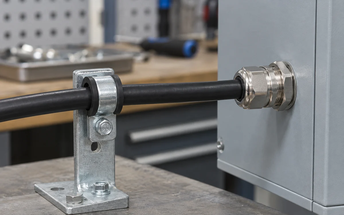
Follow the axial load through the installed assembly
A cable gland’s tensile load path is the sequence of contacts and sections carrying an axial force from the cable toward the enclosure. I inspect the cable grip first, then the cap, body, entry thread and mounting. Cable slip points toward the grip; thread damage or panel deformation points toward a later part of the path.
I follow the load from cable to enclosure. At each step, record part and material, thinnest section, joint, direction, and likely failure. If the gland only seals, retain its separate cable support in the design. If it must hold the cable, test it with the selected construction and diameter.
At a thin neck, check the metal section left by the bore and nearby thread root. At a clamping contact, check whether the cable jacket slips or suffers local damage first. At the wall, check bearing area, panel bending and locknut seating. Permanent tilt or local yielding can change the seal contact even while the body remains in one piece. A section drawing, component assessment and complete-assembly test connect these local features to the required load.
At the threaded joint, check pitch, profile, diameter, usable overlap, incomplete threads, tolerances, mating metal and load direction. Metric and NPT labels describe different joints. I use their actual drawings and applicable thread requirements to assess the connection.
Check material, component, assembly, and application separately
Use four connected checks when tensile loading can affect a cable entry. First confirm the material properties. Next assess the machined component. Then test the assembled gland with its cable and mounting arrangement. Finally compare that result with the loads and conditions at the installation.
IEC 62444:2010 covers complete-gland construction and performance. I use the relevant retention result for the selected cable and assembly, alongside the material and component assessment. A cable or accessory change directs attention back to the interfaces it affects.
Use these four checks:
- Material: Compare specified properties for the actual alloy and supplied condition.
- Component: Check the drawing, minimum section, threads, manufacturing route, surface state, and tolerances. Use a suitable analysis or component test.
- Assembly: Identify model and size, cable construction and diameter, accessories, and mounting. Direction, conditioning and installation method affect the result.
- Application: Compare static load, movement, shock, bending, vibration, temperature, and cable support with the project criteria.
A complete-gland test may show cable slip before the metal yields. It can also reveal cable damage, joint movement, locknut pull-through, distressed threads, or panel deformation. I use material properties to assess metal sections and the complete-product result to check the interfaces together.
I enter the assembly’s approved allowable retention load and the corresponding working load, then compare the resulting ratio with the project criterion. The strain-relief and sealing guide separates holding from sealing. The IEC 62444 selection guide covers complete-gland checks.
Use failure mode to decide whether more tensile strength helps
A higher-strength metal helps only when metal yielding or rupture is the governing credible failure and the grade remains suitable for the other requirements. If another interface fails first, raising body UTS may add cost or mass without improving complete-gland retention.
| Observed or predicted limit | Does higher body-material tensile strength solve it? | What to inspect next |
|---|---|---|
| Cable slides through the insert | Usually no | Verify cable construction, diameter, contact geometry, assembly, and complete retention result |
| Entry threads strip | Not by body UTS alone | Identify which mating thread fails; check material pair, usable engagement, tolerances, and local geometry |
| Thin body section yields | Possibly | Confirm exact stress state, net section, material condition, stress concentration, and allowable criterion |
| Locknut pulls through a thin panel | Usually no | Review panel thickness, hole, washer, seating area, locknut geometry, and enclosure restraint |
| Metal cracks after repeated movement | Not necessarily | Assess fatigue spectrum, bending, vibration, surface condition, notches, and cable support |
| Section is reduced by corrosion | Not by initial strength alone | Define exposure, corrosion allowance or material compatibility, inspection basis, and residual section |
Example: decide whether a stronger body addresses the failure
Consider two hypothetical designs. In the first, the gland body has ample section, but the cable jacket slips through its insert under the required axial load. I would review cable diameter, jacket behavior and the retention construction. If the application permits separate support, an appropriately placed clamp may provide the required load path. Changing the body alloy leaves the original grip problem in place.
In the second design, the cable grip and mounting meet the requirement, but a thin body neck develops permanent set. Here a higher-yield material, a larger net section or a revised geometry can address the governing limit. I compare those options with corrosion compatibility, machining and mass, then reassess the affected component and complete assembly. This is the case where a strength upgrade has a clear engineering purpose.
For cyclic movement or impact, select the corresponding assessment as well. In particular, the hardness and impact comparison treats indentation and impact as separate properties. Use the relevant indentation and impact results when those properties govern selection. Similarly, electrical conductivity needs a complete path and contact interfaces, as explained in the material-conductivity grounding guide.
Choose a material for the actual gland configuration
Choose among materials after defining the gland size and installation. I use the sequence below to compare options against the loads they will actually carry.
- Define the function. State whether the gland retains the cable, supports axial load, seals a separately supported cable, or performs an armour function.
- Define the loads. Separate cable weight, installation pull, movement, vibration, shock, bending, thermal movement and accidental load. Apply the factors required by the project design basis.
- Draw the load path. Include cable contact, cap, body, thread, locknut or threaded enclosure, washer, adaptor, and panel.
- Name credible failures. Consider cable slip or damage, stripped threads, local yield, rupture, pull-through, and panel deformation. Fatigue and corrosion loss need separate checks too.
- Compare the actual parts. Alloy, form, condition, size, accessories and cable range must suit the proposed assembly.
- Align the data. Match methods and conditions. Keep specified minimums separate from typical and single-test values.
- Apply other constraints. Reject failure of corrosion, temperature, electrical path, hazardous-area, mass, thread-fit, sealing, or access requirements.
- Verify the assembly. Match gland, cable, mounting, procedure, conditions, pass criteria, and report coverage.
This sequence identifies the part or interface that needs improvement. If the cable lies outside the gland’s range, choose a compatible retention construction. If thread overlap is insufficient, revise the joint. If the loaded metal section governs, compare an appropriate grade or geometry change. Each action addresses the reason the current design falls short.
Recheck the decision after any configuration change
Repeat strength and retention checks after a configuration change. Review size, body shape, cable diameter or construction, insert, and cap. Then check entry thread, locknut, adaptor, and panel thickness. A changed grade, temper, coating, manufacturing route, or installation method also needs review.
An apparently minor change can move the weakest point. For example, a smaller size can reduce a local wall section. A longer entry thread may increase engagement but also change manufacturing details. Meanwhile, an anodized aluminum surface can affect electrical contact without changing the core tensile-property record. A harder mating nut can shift thread damage into the gland body. A softer cable jacket can reduce usable retention even when every metal component stays unchanged.
For a size-family comparison, identify which size is most demanding for each failure mode. The thinnest body neck, shortest usable engagement and most demanding cable grip may occur in different sizes. I use those relationships to select the representative assessments and tests.
Conclusion: choose strength where it improves the load path
I select the material after identifying the governing part of the installed load path. A higher-strength grade helps a metal section that would otherwise yield or rupture. A grip, thread or panel problem calls for a change at that interface. Brass, stainless steel and aluminum remain candidates where their exact grades, geometry and other properties meet the duty.
Compare yield strength, UTS and ductility with their test conditions. Then check the assembled gland with its cable and mounting, including relevant temperature, movement and exposure. This connects the material choice to the behavior the installation actually needs.
FAQs about metal cable gland tensile strength
Is 316L always stronger than brass or aluminum cable glands?
Compare the exact grades, supplied conditions and part geometry. A 316L material value can be higher than a particular brass or aluminum value, while cable slip or a thin panel still controls the installed assembly. I choose the grade and gland construction together, including corrosion and mass requirements.
What is the difference between yield strength and ultimate tensile strength?
Yield strength describes a specified permanent-deformation response. Ultimate tensile strength is the maximum engineering stress reached by the tensile specimen. I use the first in deformation checks and the second in material rupture comparisons, then assess ductility and the component’s actual geometry.
How do I establish cable pull-out capacity?
Use the retention result for the selected gland, cable and mounting arrangement. Examine the cable contact, insert, cap, threads, locknut and panel to identify the governing failure. For a metal-section calculation, add its dimensions, loading, material condition and applicable acceptance criterion.
How should I choose a gland for vibration?
Review the vibration conditions, cable support, bending and joint stability, then use the applicable component or assembly assessment. I check whether movement reaches the body, grip or mounting thread. Static tensile properties support the metal assessment; cyclic loading also needs an appropriate fatigue evaluation.
How does IEC 62444 help with material selection?
IEC 62444 addresses construction and performance requirements for complete cable glands. I use the relevant product result to assess the supplied gland configuration, then compare alloy properties where a metal section governs the design. Both inputs need to match the intended installation and exposure.
Sources and technical references
-
ASTM International - E8/E8M, Standard Test Methods for Tension Testing of Metallic Materials, accessed 2026-10-28.
-
ASTM International - A276/A276M-25, Standard Specification for Stainless Steel Bars and Shapes, accessed 2026-10-28.
-
ASTM International - B16/B16M-24, Standard Specification for Free-Cutting Brass Rod, Bar and Shapes for Use in Screw Machines, accessed 2026-10-28.
-
ASTM International - B221-21, Standard Specification for Aluminum and Aluminum-Alloy Extruded Bars, Rods, Wire, Profiles, and Tubes, accessed 2026-10-28.
-
IEC 62444:2010 - Cable glands for electrical installations, accessed 2026-10-28.
-
U.S. Department of Energy — DOE-HDBK-1017/1-93, Material Science, Module 2, strain and ductility, accessed 2026-10-28.
-
NIST — Martin et al., Effect of strain rate on tensile test results in hydrogen and other concerns, 2025, accessed 2026-10-28.
-
AMPP — Stress Corrosion Cracking, accessed 2026-10-28.
-
British Stainless Steel Association — General principles for selection of stainless steels, accessed 2026-10-28.
-
British Stainless Steel Association — Can I use stainless steel at low temperatures?, accessed 2026-10-28.
-
Liu, Mirza and Chen — Effect of Overaging on the Cyclic Deformation Behavior of an AA6061 Aluminum Alloy, 2018, institutional full text, accessed 2026-10-28.
-
ASTM International — B858-06(2024), Ammonia Vapor Test for Determining Susceptibility to Stress Corrosion Cracking in Copper Alloys, accessed 2026-10-28.
-
ASTM International — F519-23, Mechanical Hydrogen Embrittlement Evaluation of Plating/Coating Processes and Service Environments, accessed 2026-10-28.