

Cable gland material conductivity affects grounding only when the design assigns the gland a conductive role. I trace the full path before comparing metals. Bulk conductivity describes one segment. Cable contacts, body geometry, plating or oxides, entry hardware, enclosure finish, and joint condition can govern the assembled resistance. A metal name cannot prove protective bonding, fault-current capacity, or dependable continuity.
Key takeaways
- Bulk conductivity matters only inside a path that the design intentionally assigns to the gland.
- Exact alloy, condition, plating, geometry and effective cross-section matter more than a generic material label.
- Contact pressure, surface films, coating, contamination, corrosion and accessory interfaces can outweigh the body-material difference.
- Protective bonding, armour continuity and EMC screen termination are different electrical functions with different evidence.
- Measure and assess the complete installed path; do not approve a configuration from an isolated material value.
Conductivity is a material property, not a grounding result
Electrical conductivity is a material property that describes how readily a specified material carries current under defined conditions. Its reciprocal, resistivity, can help compare material samples. Neither value says whether current can enter the gland, cross its joints, leave through the enclosure interface and return along the intended protective path.
IEC 60364-5-54 covers earthing and protective conductors, including bonding conductors, at installation level. I use that boundary to identify the path and protective function. A conductive entry component alone cannot establish the protective measure.
IEC 62444:2010 gives complete-gland construction and performance requirements. I assess the supplied assembly and its declared role. Brass, aluminium, or stainless labels cannot supply that evidence.
Three cases make the boundary clear:
- Outside protection. A dedicated protective earth (PE) conductor provides the bond. The gland seals and retains cable.
- Inside an assigned path. Body material matters with cable contact, accessories, entry hardware, and enclosure joint.
- Another assigned function. Electromagnetic compatibility (EMC), static control, or armour continuity does not automatically establish fault-current duty.
I use the electrical bonding and grounding guide to trace the return to the source and protective-device coordination. The material checks below show where conductivity contributes and where its predictive value ends.
Bulk conductivity describes a defined material volume, not finished-joint resistance. It supports comparison when alloy, condition, temperature, and geometry match. A gland adds cable-side and enclosure-side contacts, joints, and accessories. They can change current route and effective area.
I use handbook values for material characterization. They cannot establish installed continuity or fault suitability. First assign the electrical role, then match cable, gland, and accessories to product documents. Assess the actual current entry and exit interfaces with the complete path.
The assembled path contains several resistance segments
An assembled grounding path is the full conductive route between the protective function’s defined endpoints. A low-resistance body may still have unsuitable contacts. I review each bulk section and contact transition. Their geometry, surface state, and mechanical condition all matter.
| Path segment | Material-related input | Interface or configuration input | Evidence that matters |
|---|---|---|---|
| Cable-side handoff | Contact-element alloy and finish | Correct cable layer, contact area, pressure, surface preparation | Exact gland/cable/accessory instructions and represented assembly |
| Gland body | Exact alloy, temper, coating or plating | Wall section, length, threads and current route | Drawing, material specification and component declaration |
| Entry accessories | Earth tag, washer, locknut or adapter material | Stack order, seating, usable thread and joint pressure | Parts list, drawing and assembly instructions |
| Enclosure-side handoff | Enclosure and hardware materials | Paint, oxide, contamination, flatness and anti-rotation | Enclosure-entry design and controlled installation method |
| Downstream bond | Conductor and terminal materials | Conductor size, termination and return route | Installation design and applicable protective criteria |
Why generic material rankings fail
Brass, aluminium, and stainless families contain different alloys and production states. Finishes may include plating, passivation, anodizing, or coating; parts may be machined or cast. I identify the actual grade and treatment. Geometry defines the effective conducting section, while mating materials and surfaces determine contact.
For a useful comparison, I record at least:
- the exact alloy or polymer grade and its production condition;
- any plating, passivation, anodizing or coating, including which contact areas remain electrically functional;
- the body and accessory geometry along the proposed current path;
- the mating enclosure material and finish;
- the cable layer being contacted, such as armour, braid, screen or a dedicated earth accessory;
- the environmental exposure that can change surfaces or joint pressure;
- the current type, duration and functional purpose the route is expected to serve.
For equal geometry, higher bulk conductivity can reduce body-segment resistance. I still compare the complete joint. Changed section, length, film, pressure, or accessories can outweigh that benefit. Lower conductivity also cannot reject a material automatically when the path bypasses the gland or the assembly has suitable evidence.
I keep magnetic response separate. Magnetic permeability describes response to a magnetic field. The magnetic-permeability guide separates it from conductivity, corrosion, and assembly performance.
Contact interfaces can control the outcome
Current crosses microscopic contact spots at a real joint. Films, roughness, pressure, and contamination affect that area. I check these interfaces even with a sound bulk conductor. Nominal material alone cannot establish contact.
On the cable side, I identify the intended metal layer. Armour wire, braid, foil, and drain conductors are different constructions. Jacket or bedding may isolate nearby metal. Follow the approved cutting, folding, and distribution method; changed preparation can alter electrical contact and retention.
On the enclosure side, I check whether paint or powder coat interrupts the intended route. Removing finish without an approved method may create corrosion or invalidate the enclosure process. Use the declared bonding feature, compatible hardware, or another documented arrangement preserving mechanical and environmental requirements.
Contact resistance is resistance to current crossing between mating parts. It depends on real contact spots, not apparent touching area. Oxides, coatings, roughness, contamination, pressure, movement, and corrosion can change it. A more conductive body may help little if the limiting interface stays unchanged.
I identify current-carrying surfaces, how contact pressure is established, and environmental changes that may affect them. Include both cable-side and enclosure-side contacts in the complete-path measurement. Visual contact or the easiest exposed test point cannot establish the intended result.
I follow the assembly instructions for joint pressure. Too little may make contact unstable. Extra tightening can damage threads, deform accessories, disturb seals, or exceed the permitted method. There is no generic torque that establishes all interfaces.
I assess corrosion over time. Mixed metals, conductive liquids, cleaners, and surface damage can alter an initially acceptable contact. The bi-metallic corrosion guide evaluates that pairing and exposure. Conductivity alone cannot predict durability.
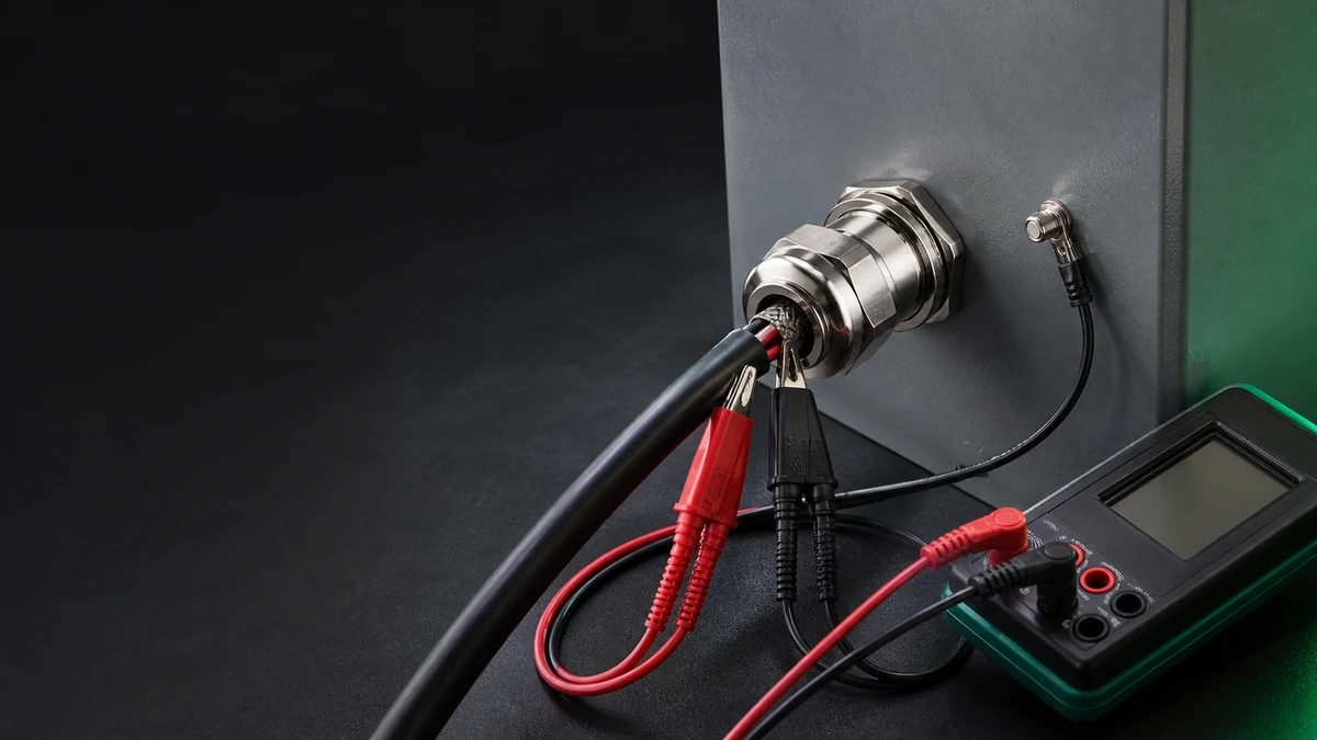
Clip leads connect the cable-entry area and a separate panel fastener to the nearby meter.
I interpret resistance using the specified range, endpoints, method, uncertainty, and system criterion.
Protective bonding and EMC require separate evidence
Protective bonding and EMC screen termination are distinct functions. Bonding concerns the assigned safety path and its electrical conditions. EMC concerns screen-contact impedance, frequency, and geometry. I require evidence for each, even when one gland participates in both.
Low-frequency continuity cannot establish high-frequency shielding. EMC transfer impedance cannot qualify fault-current duty either. I use the transfer-impedance testing guide to interpret frequency-dependent assembly evidence separately from material conductivity.
I keep these declarations separate:
- Protective bonding: the assigned conductor or conductive route, connection method and system acceptance criteria.
- Armour continuity: the exact armour construction, gland contact and any required current-carrying function.
- EMC screen termination: the represented cable screen, circumferential contact, frequency range and assembly method.
- Functional or static earth: the equipment function and its own current, impedance and environmental boundary.
- Lightning current path: only a specifically designed and coordinated lightning-protection route; never inferred from a metal gland.
One assembly may perform several functions. I match evidence to each claimed boundary.
Read the complete path before selecting a material
The diagram separates the path into three segments. Conductivity influences the middle segment, while the two handoffs can determine whether current reaches or leaves it at all.
I identify contact features from approved product and installation records. Then measure the assembled route by the system method and acceptance criterion.
Complete-joint measurement needs a declared decision rule
I choose test points representing the assigned route. Measuring the body alone omits contact interfaces that may change during installation or service. Define current-injection and voltage-sensing points to include the intended cable and enclosure handoffs.
IEC 61557-4:2019 covers instruments for resistance measurements of earth, protective, and equipotential-bonding conductors, including connections and terminals. It supplies no universal gland-joint acceptance value. I obtain that value from the installation, product, or system requirement.
For low resistance, I account for lead and contact effects. Four-terminal methods use separate sensing connections to reduce current-lead voltage-drop effects. The method still needs suitable range, connections, and uncertainty. NIST Technical Note 1458 describes its traceable resistance-measurement service. It cannot approve gland assemblies or supply their field limits.
Complete-path resistance is measured between endpoints chosen for the assigned route. Where the gland forms part of a bond, include cable-side and enclosure-side interfaces. I record assembly, range, lead arrangement, environmental state, and uncertainty with the result.
Use a decision rule from the applicable requirement. A low reading can confirm one aspect of that route at measurement time. It cannot alone establish fault capacity, device coordination, EMC, or long-term corrosion stability. Do not invent one field limit for all glands.
I record the following so the decision can be reviewed:
- the electrical function and exact current path being assessed;
- gland, cable, entry and accessory configuration;
- material grades, finishes and relevant surface preparation;
- measurement points, instrument, method, range and uncertainty basis;
- environmental or conditioning state;
- the source of the acceptance criterion and the decision made.
I use a continuity beep to help locate an open circuit. It cannot establish resistance suitability, capacity, thermal response, or stability of the assigned route. An initial low reading also cannot establish corrosion durability. Match measurement and exposure evidence to the claim.
A practical material-and-path review
Before selecting on conductivity, I follow this sequence:
- Name the function. Identify protection, armour continuity, EMC, or another defined route.
- Draw the route. Include layer, contacts, body, accessories, enclosure, and downstream bond.
- Mark interfaces. Include coatings, threads, washers, locknuts, tags, adapters, and mixed metals.
- Specify materials. Record alloys, states, finishes, and conducting geometry. Family names are incomplete.
- Match evidence. Confirm cable, size, accessories, entry, and instructions within the claim.
- Review exposure. Check moisture, chemicals, salt, vibration, thermal cycling, and maintenance effects.
- Measure the assigned path. Use defined endpoints, suitable method, and applicable criteria.
- Verify other functions. Keep sealing, retention, EMC, and protective bonding under separate requirements.
Conclusion
Conductivity may improve one gland segment. I assess grounding through the entire assigned route. Alloy and geometry matter after current duty is established. Contacts, films, accessories, finish, pressure, and corrosion then affect whether the route remains usable.
I choose materials for function, assembly, and environment. Verify both contact handoffs as carefully as the body, then measure the route against the system criterion. Complete-joint evidence supports the decision more directly than a generic metal ranking.
FAQs about cable gland material conductivity
Does a brass cable gland automatically provide better grounding than stainless steel?
No. Bulk conductivity is only one input. Exact alloy, geometry, plating, contact area, surface condition, accessories, enclosure interface and assigned electrical function determine the assembled path. Compare complete configurations, not generic material names.
Does every metal cable gland need to carry protective fault current?
No. A design may use a dedicated protective conductor while the gland provides sealing and retention. A gland carries protective current only when that role is intentionally assigned and supported by the applicable component and installation evidence.
Can a continuity test prove that a cable gland is safely grounded?
No. A simple continuity indication can find an open circuit, but it does not establish suitable resistance, current capacity, thermal behavior, protective-device coordination or long-term stability. Test the defined complete path with the applicable method and acceptance criterion.
Does an EMC cable gland automatically provide protective bonding?
No. EMC screen termination concerns frequency-dependent impedance and screen geometry. Protective bonding concerns an assigned safety path under different conditions. One assembly may support both, but each function needs separate evidence.
Can paint be removed around a gland entry to improve conductivity?
Only when the enclosure and product instructions allow a controlled bonding surface and the corrosion and environmental consequences are addressed. Unauthorised finish removal can damage protection or create a new failure site; use the declared interface method.
Sources and technical references
- IEC 60364-5-54:2011 — Low-voltage electrical installations: Earthing arrangements and protective conductors, accessed 2026-09-08.
- IEC 62444:2010 — Cable glands for electrical installations, accessed 2026-09-08.
- IEC 61557-4:2019 — Equipment for testing, measuring or monitoring protective measures, accessed 2026-09-08.
- NIST Technical Note 1458 — NIST Measurement Service for DC Standard Resistors, accessed 2026-09-08.