

Choose a cable gland for unarmoured cables by matching its seal and grip to the actual jacket contact zone. I locate a continuous, sound section of the specified layer, then compare its dimensions, shape and contact length with the gland instructions. Measure where the gland will sit and inspect that full band for damage or a change of surface.
Cutback, a marker sleeve, repair, or a tight bend can move a different surface under the seal. I set the contact location before accepting the cable and gland as a pair.
Key takeaways
- Locate the cable layer and full contact length named by the gland’s drawing and instructions.
- Check dimensions and jacket condition at that location, including relevant variation around the cable.
- Separate an incompatible cable profile from a local defect that may allow another intact contact location.
- Treat tape, sleeves, and boots as changes to the contact surface, not automatic diameter corrections.
- Keep the selected section at the gland’s contact zone after routing, support, and permitted preparation.
Locate the jacket surface the gland is meant to contact
The jacket contact zone is the finished-cable section meeting the gland’s seal or grip. If the design specifies the outer jacket, that layer must continue through the full required band. I locate it from the product instructions, then check the entry thread and wall seal as separate mounting interfaces.
I compare the cable construction with the gland section drawing. Locate where each seal or grip starts and ends and how closure positions the cable. Unarmoured flexible cable can still contain screens, fillers, textile reinforcement, and several insulation layers. The construction comparison helps when these layers are uncertain.
IEC 62444:2010 addresses complete supplied glands. Match the actual cable layer to the selected assembly’s stated use, including separate sealing and gripping locations where the design has them.
I obtain preparation and contact length from the exact instructions. Plan the termination cutback to leave the required jacket inside the gland while giving the cores enough length to reach their terminals. Check that cutback after routing: exposing cores within a seal designed for the outer jacket changes the contact surface and requires a different permitted arrangement.
Check the contact band rather than one convenient diameter
Cable dimensions matter at the intended contact location and condition. I compare full permitted variation with the exact seal or grip’s range and profile. An intact-area reading cannot represent a damaged or flattened section that will sit inside the gland.
IEC 60811-203:2012 gives overall-dimension methods for round and flat cables. I use the cable specification for measurement and acceptance rules, then compare those dimensions with the selected gland’s stated cable range and permitted profile.
I check positions along and around the band and retain relevant extremes. One average may hide major and minor dimensions. Use a suitable tool and method without uncontrolled pressure on the jacket. Keep location, dimensions, and surface condition together.
The clamping-range guide explains layer-specific ranges. I check whether the actual surface stays within dimensional and construction limits throughout the required contact length.
| Contact-zone observation | What I do next |
|---|---|
| Intact continuous jacket, permitted profile | Compare full dimensional variation with cable-facing range |
| Major/minor dimensions outside permitted shape | Choose an interface for that profile |
| Local indentation or flattening | Assess another sound position if routing/preparation permit; establish condition before reuse |
| Cut, abrasion, displaced material | Apply cable repair/replacement procedure |
| Raised seam, rib, label, or step | Check permitted surface and profile; nominal outside diameter (OD) is insufficient |
| Cutback, joint, boot, or sleeve in band | Identify resulting contact material and shape within the assembly |
Separate profile mismatch from local jacket damage
Profile mismatch means the intended cable shape falls outside the selected seal’s permitted profile. A sound flat or oval cable may need a different seal design. A round cable may instead have local damage. I choose the correction from that distinction and use the closing force specified for the compatible arrangement.
For designed non-circular cable, I use dimensions and an interface permitted for the shape. The non-circular guide covers profile and orientation. Moving along the same incompatible section cannot create a suitable round surface.
For a local defect, I look for a sound zone while preserving preparation, termination, and route. A crushed band near an old clamp can be unsuitable despite the correct cable designation. Cuts and abrupt surface transitions also need local assessment. Move the contact only if the new zone meets requirements and leaves enough termination length.

Cold flow is gradual deformation under sustained load. I compare a changed jacket profile with its loading history and acceptance criteria before assigning that cause. The cold-flow guide explains its effects at defined interfaces. Use the actual condition and product limits to decide whether the contact location remains suitable.
Decide whether preparation leaves a usable jacket
Permitted preparation leaves the specified surface at the specified contact position. I follow the exact cable and gland instructions for cutback, cleaning, insertion and allowed aids. Use their stated stripping distance, cleaning agent and closing method for the selected materials.
I protect the eventual sealing section from sharp end parts and passage edges. Check that jacket still spans the band after routing to the terminal. Pulling cable farther inward can move its cutback into a previously suitable zone.
Flat printing is not automatically an incompatible surface. Raised labels, wraps, and marker sleeves can change shape and contact material. I place identification as permitted while preserving both the band and circuit identification. Do not sand, scrape, or dissolve markings to improve appearance.
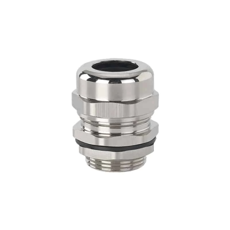
I locate seal and grip from the section drawing. If they act at different positions, both need their intended cable surface. Keep screen termination and other preparation within the specified arrangement so another interface retains its required jacket.
Treat tape and sleeves as changes to the sealing surface
An added layer is a wrap, sleeve or boot that becomes the gland’s contact surface. It changes diameter, shape, material and the underlying joint. I assess its sealing and retention arrangement separately from its electrical-insulation rating.
I use added layers only where the exact system permits them and defines assembly. Identify the surface contacted and how the layer is retained. Bare-jacket evidence cannot automatically cover overlaps, adhesives, or end transitions.
For an undersized cable, I choose a gland or insert with a declared range covering that cable. For local damage, use the cable’s permitted repair or replacement procedure before selecting the contact zone. Tape or a sleeve belongs under the gland only where the complete arrangement expressly covers it.
I check sleeve or boot ends as well as central diameter. The whole band needs the surface and length covered by the declared arrangement. Edges, overlaps, steps, or unsupported regions may create another condition. Resolve it before choosing size.
Keep the selected zone straight and supported
The usable jacket must remain in the intended contact position after final routing. I plan approach, bend, supports, and termination length together. The section that fits at the bench may shift when cable is pulled into place.
I follow cable bend limits and gland installation instructions. Route weight, handling pull, and movement must not force side load at the band or terminal. The strain-relief guide separates seal, retention, and independent support.
For U.S. flexible-cord and cable connections within its scope, OSHA 29 CFR 1910.305(g)(2)(iii) requires strain relief to keep pull from reaching joints or terminal screws. Apply the relevant equipment and local installation requirements to the actual cable route. The selected jacket contact zone is one part of that arrangement.
Before closure, I recheck each seal/grip location after routing and support adjustment. If cutback, damage, sleeve edges, or forced bends enter the band, change the location or cable arrangement. Extra tightening cannot fix it.
Three jacket-location decisions
I choose the correction from the reason the contact zone is unusable. Local damage, profile incompatibility, and added layers need different decisions. Check whether another sound position resolves it or whether the interface must change. Retain the preparation and route supporting that choice.
Local indentation with sound jacket nearby. Consider a hypothetical control cable with a flattened band left by an old clamp. A sound section farther along the cable may provide a new contact location, but first check the route and termination length. I mark the full seal and grip positions from the gland drawing, then check that both will land on intact jacket after the cable reaches its terminals. Measure the proposed section using the cable specification’s method and compare its full dimensional variation with the gland’s limits. Moving the gland also changes where the bend and support sit, so check those positions before cutting back the jacket. If the new location leaves too little termination length or forces an unsuitable bend, use the permitted cable repair or replacement route. This decision depends on the usable section in the final installation, not just a sound patch visible on the bench.
Sound cable outside the seal’s permitted profile. For example, a flat unarmoured cable may have a smooth, undamaged jacket but still fall outside a round seal’s permitted shape. I compare its width, thickness, corner shape and allowed variation with an interface intended for that profile. Averaging the width and thickness would discard the very geometry the seal must contact. Moving to another straight section of the same cable preserves that profile, so the correction is a compatible gland or entry arrangement. Check the orientation required by its instructions as well as the dimensions. Then confirm that routing, support and termination allow the cable to remain in that orientation through the contact zone. If the route twists or bends the cable at the seal, revise the approach or choose another permitted arrangement before closing the gland.
Sleeve crossing the proposed band. I check whether the system covers the exact sleeve, cable, contact material, and assembly. If covered, follow its geometry and preparation. Otherwise choose sound finished jacket or another permitted arrangement. Electrical rating cannot establish entry suitability.
After choosing a usable contact location, I check mounting and complete-entry performance with the specified gland, cable and accessories. IEC 60529 addresses enclosure ingress protection (IP), so keep the assessment tied to that installed configuration and its test conditions.
Conclusion
I locate the specified surface throughout the contact band, assess its profile and condition, and keep it in position through preparation and routing. A nominal diameter elsewhere cannot correct damage, cutback, or a sleeve at the actual seal or grip.
I use sound permitted jacket for a local defect, a compatible interface for a designed shape, and an expressly covered arrangement for an added layer. Keep jacket zone, supports, preparation, and complete entry consistent with that decision.
FAQs about selecting a cable gland for unarmoured cables
Where should an unarmoured gland contact the cable jacket?
I follow the exact drawing’s surface and contact length. Where outer jacket is specified, keep it continuous through the band. Position termination cutback clear of the band after routing and support.
May a cable identification marking sit inside the contact zone?
A flat printed marking is not automatically an incompatible surface. A raised label, wrap, or marker sleeve can change the local profile and material. Check the permitted cable surface and keep identification in an allowed position. Do not remove or alter the jacket with an unlisted scraping, sanding, or solvent procedure to improve its appearance.
Can extra tightening make an oval jacket fit a circular seal?
I use the documented closing method only for a permitted profile. Extra force cannot authorize an incompatible oval shape and may change the seal or jacket. Compare major/minor dimensions and select a profile-compatible interface where needed.
Can heat-shrink sleeving replace missing jacket under the gland?
Only when the exact cable-entry arrangement permits that preparation or sleeve and defines its use. The added layer changes the contacted material, diameter, length, and underlying interface. Otherwise use an appropriate intact finished-jacket section or the permitted cable repair or replacement route; the sleeve’s electrical-insulation rating alone does not establish gland suitability.
Does an intact jacket prove that the entry meets its IP marking?
No. The usable jacket is one input to the cable-facing interface. The exact gland, insert, closing method, mounting seal, enclosure, support, and required verification still need to describe the resulting assembly. An enclosure ingress claim comes from its applicable configuration and conditions, not from appearance or one acceptable diameter reading.
Sources and technical references
- IEC 62444:2010, Cable glands for electrical installations, accessed 2026-10-28.
- IEC 60811-203:2012, Measurement of overall cable dimensions, accessed 2026-10-28.
- IEC 60529 consolidated version, Degrees of protection provided by enclosures, accessed 2026-10-28.
- OSHA 29 CFR 1910.305, Wiring methods, components, and equipment for general use, accessed 2026-10-28.