

The choice between dome top or flex-protectant cable glands starts with the cable route. For a straight, well-supported cable, I would usually choose the more compact dome-top profile. A flex-protectant model is useful when a cable turns close to the enclosure and its sleeve provides a smoother transition. I compare projection, bend space and cable range, then support, sealing and movement duty for the actual installation.
The exterior shape is only one part of that decision. Ingress protection and cable retention come from the complete gland and entry arrangement, while continuous machine movement depends on the cable and routing system as a whole.
Key takeaways
- Dome-top designs suit straight, supported routes where compact projection and tool access matter.
- Flex-protectant designs suit close bends or recurring side contact when the sleeve geometry matches the cable.
- The cable manufacturer’s bend radius and movement rating govern the route.
- An external sleeve guides the cable near the gland; a separate clamp or cleat may still carry weight, pull or lateral load.
- IP performance and cable retention belong to the exact gland, cable, entry and assembly tested for those functions.
How should dome top or flex-protectant designs be compared?
A dome-top profile has a rounded or tapered compression nut and short cable exit. It keeps projection low, leaving room for tools, doors, conduit and nearby entries. The cable’s free route starts soon after the gland, so support position and bend space influence local load.
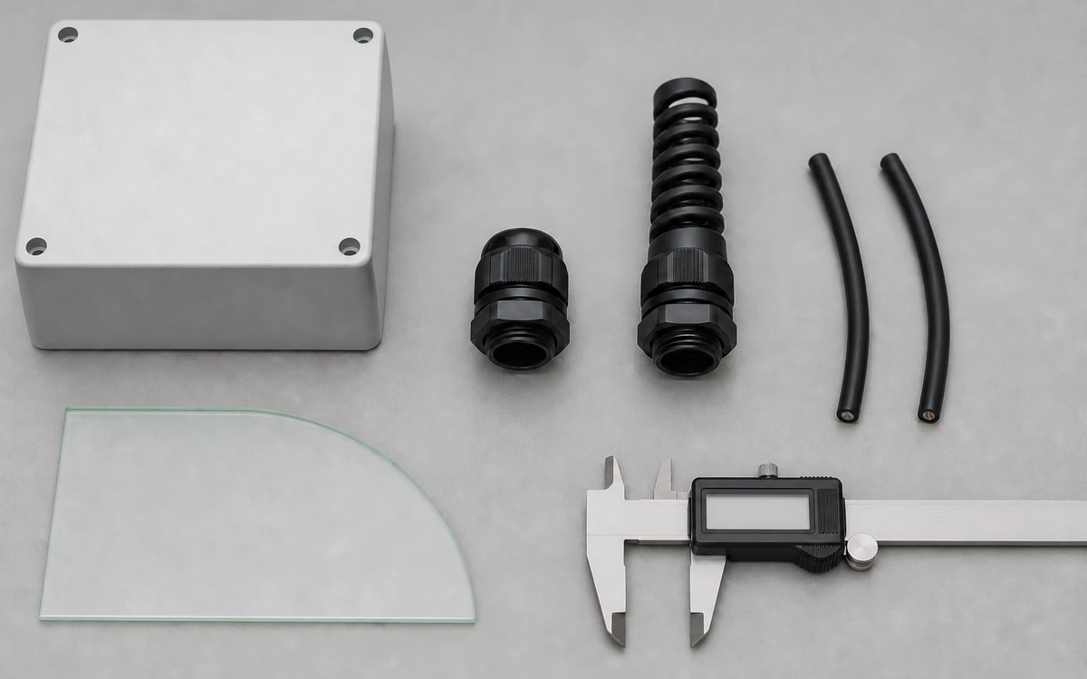
A flex-protectant profile adds a spiral, sleeve or tapered extension after the nut. It guides the cable farther and can spread contact around a bend. It also projects farther and moves the free bend away from the wall. I check the drawing to see whether the sleeve is integral or a separate accessory.
These names describe geometry, not standardized performance classes. Either profile can have different materials, seals, cable ranges, threads and retention systems. I therefore compare full part numbers and dimensioned drawings.
Which profile fits a straight, supported route?
I would consider a dome top when the cable leaves on axis and reaches support through clear space. Its short projection preserves room in compact cabinets and helps keep the nut accessible. The route still needs installation space and the cable’s permitted bend radius.
For example, a heavy vertical cable may load an entry continuously even on stationary equipment. A nearby clamp, tray or cleat can carry that load. I check cable range, material, IP result and retention for the exact assembly; dome shape alone does not establish them.
I would stage the exact dome-top gland with the cable running straight to its first independent clamp. Put the intended service wrench on the cap flats. Check that it can engage and withdraw clear of the door return and rail. The projection, support position and working space need to fit the drawing and instructions.

When does a flex support help?
An external flex support can help a cable that turns soon after the entry, encounters recurring contact or receives a predictable lateral load. Its longer contact can smooth the change in direction. I check sleeve stiffness and length to see whether that benefit fits the route. A short, soft sleeve allows an earlier bend; a long or stiff one moves it outward and needs more clearance.
For example, a nearby wall may conflict with the added projection. The drawing must show overall gland length and where the cable becomes free to bend. I also check that the cable fits the sleeve without pinching or a radius below its limit. Diameter, jacket hardness, temperature and construction affect that fit. The first clamp or cleat still matters because the sleeve controls the local transition.
With the equipment stopped, I would mock up the route using the proposed gland and first independent clamp. Mark the sleeve end and first curve as separate reference points. Place an unmarked template against the outside bend, then check its start, occupied space and wall clearance. Compare the geometry with the gland drawing and the cable maker’s limits.

How much bend space is required?
Minimum bend radius is the smallest radius permitted for the stated cable, condition and duty. Installation, fixed service, repeated flexing and cold handling may have different values. I use the exact cable designation to choose the applicable one.
Bend-start position is where the cable becomes free to curve after the cap or sleeve. It may lie near a dome cap or farther out at a flex sleeve’s end. I reserve space for projection, sleeve length, straight lead, radius, cable diameter and first support. Doors, tools, terminals and adjacent entries may reduce that space.
I use the calculated arc as a layout estimate. The final route also needs allowance for manufacturing tolerance, stiffness at operating temperature, installation handling and the most demanding moving-hardware position.
Static bends, vibration and continuous movement
A fixed cable can still carry weight and experience vibration, thermal movement or maintenance loads. I check bend geometry even when normal operation is stationary. Both gland profiles can serve a fixed route if dimensions and material limits fit.
For occasional door or panel movement, I allow enough free cable to avoid pulling terminals, rubbing edges or tightening the bend. Support positions determine where that movement is taken up.
Continuous movement needs its own motion path, speed, acceleration, torsion, cycle count and moving radius. The cable, carrier or guide, supports and termination all participate. A gland sleeve may improve the local transition. Service life still needs a cable and routing system intended for that movement.
Sealing, retention and support are different functions
IEC 62444:2010 covers requirements and tests for complete cable glands as supplied by the manufacturer or responsible supplier. The IEC page states that it covers construction and performance and applies directly to cable glands with IEC 60423 metric entry threads, while offering guidance for other entry-thread types. The exact gland model, seal, cable range, entry arrangement and assembly instructions determine which results apply.
Cable retention describes resistance to axial cable displacement under stated product requirements. Bend control shapes the cable path near the exit. External support carries the routed cable at a clamp, cleat, tray or carrier. A flex sleeve can contribute to local bend control while a separate support carries weight or pull.
IEC 61914:2021 covers cable cleats and intermediate restraints used to secure cables in electrical installations. Its scope includes products that rely on a manufacturer-specified mounting surface for declared axial or lateral retention. This makes the support position, mounting and cable arrangement part of the support selection.
For United States workplaces, OSHA 29 CFR 1910.305 includes strain-relief requirements for flexible cords and cables so pull is kept away from joints and terminal screws. Other jurisdictions and equipment standards can apply different requirements, so project location remains part of the design basis.
IEC 60529 classifies protection provided by electrical-equipment enclosures. The IP result belongs to the tested enclosure or entry arrangement and its stated assembly. I check the exact cable, seals, thread or hole, wall, accessories and method for either profile.
For severe water exposure, the deluge-proof cable-entry guide covers runoff, pooling, washers, threads and complete-entry conditions.
Comparing two exact gland models
I use photographs for an initial shape comparison and drawings to check fit. The table below separates route geometry, cable fit and product functions.
| Selection item | Dome-top model | Flex-support model |
|---|---|---|
| Overall projection | Body, cap and cable-exit length | Body, cap, sleeve and cable-exit length |
| Bend start | Position where cable clears the cap | Position where cable clears the sleeve |
| Cable fit | Permitted cable type and diameter range | Permitted cable type and diameter range through the sleeve |
| External support | Distance and direction to clamp, cleat, tray or carrier | Distance and direction after the guided transition |
| Service access | Tool envelope and nearby hardware | Tool envelope plus sleeve clearance |
| Environment | Body, seal and cable material limits | Body, seal, sleeve and cable material limits |
| Product functions | Sealing and retention data for the complete gland | Sealing and retention data for the complete gland |
| Movement | Fixed or stated movement conditions | Fixed or stated movement conditions for the cable and route |
I check suffixes because a sleeve may be optional, removable or offered in several lengths. The code, drawing revision and instructions identify what is included. Thread designation alone leaves cable range and projection unresolved. The M20 cable-gland specification guide explains how the entry thread relates to the rest of the gland.
I review every exposed material. A nylon body, elastomer seal and flexible sleeve may have different heat, chemical, UV and aging limits. Metal bodies also require corrosion and bonding checks. The service conditions apply to the full construction.
Three installation examples
Straight instrument cable in a compact cabinet
Here the cable leaves horizontally, reaches a clamp through clear space and then bends. I would consider a dome-top model to save projection and preserve wrench clearance. I would still check cable range, entry dimensions, seals, retention and material limits.
Fixed cable turning beside an enclosure wall
Here the cable turns downward soon after the entry. I would consider a flex support to guide it toward the clamp and move the sharpest curvature away from the cap. Sleeve length, fit and stiffness must still leave the permitted radius within the available space.
Cable travelling with moving machinery
For a cable that moves every cycle, I start with a moving-duty cable and defined travel path. I then check the carrier or guide, support spacing and termination. The gland profile must fit that system. A longer sleeve may improve the entry transition, while the moving cable and routing parts determine permissible travel and service life.
Direct cable entry and flexible conduit also need separate treatment. The liquid-tight cord-grip and conduit-fitting guide explains how a fitting that terminates conduit differs from a gland that seals and retains a cable directly.
What changes the original selection?
When a cable is replaced, I recheck diameter, jacket stiffness, bend radius and movement rating, even if its conductors serve the same function. A changed gland, seal, sleeve or adaptor may move the bend start or reduce tool access. Relocated support, a new enclosure or an added door also changes the route.
During inspection, I look for concentrated jacket wear, cable migration and damaged or displaced support. A cracked sleeve, loose gland, distorted entry or tighter bend also changes the intended load path. These observations guide a check of local contact, axial load and retention.
I match the response to the finding. A routing conflict may need support relocation or clearance. Repeated movement may need a dedicated moving-cable arrangement. Water entry needs investigation of both cable-to-gland and gland-to-wall seals. The exterior profile is one part of that review.
Conclusion
For a straight, supported route with limited projection and service space, I would usually consider a dome-top gland. For a close bend or recurring side contact, I would check whether a flex-protectant sleeve gives a useful longer transition. Its length, stiffness and bend-start position decide whether it fits.
I check sealing, retention, external support and movement duty separately. I combine the exact drawing with the cable maker’s bend limits, route geometry, support position and environment, then verify product information for the assembled entry.
FAQs about dome top and flex-protectant cable glands
Does a flex-protectant gland last longer on moving machinery?
A flexible exterior alone provides no cycle-life value. Continuous movement depends on the cable’s movement rating, travel path, bend radius, torsion, carrier or guide, support points, termination and test conditions. The gland sleeve addresses only the local transition at the entry.
Does a dome-top gland have a higher IP rating?
Cap shape does not set the IP code. The applicable result belongs to the tested enclosure or cable-entry arrangement, including the exact gland, cable, seals, entry geometry, accessories and assembly method.
Can an external flex support replace a cable clamp?
The two parts normally perform different jobs. A flex sleeve guides the cable close to the gland, while a clamp or cleat carries stated axial or lateral loads at its mounting point. The route design determines whether both are needed.
How is the required cable bend radius chosen?
The applicable radius comes from the cable manufacturer for the exact cable, temperature, installation condition and movement duty. Installation, fixed-service and repeated-flex values can differ.
What information is needed to compare two gland models?
I need full part numbers and drawings first. Then I compare cable range, exit projection, bend start, thread and wall fit. Materials, seals, accessories, supports, route loads and environmental limits follow. Instructions and stated movement conditions complete the comparison.
Sources and technical references
- IEC 62444:2010 - Cable glands for electrical installations, accessed 2026-09-11.
- IEC 60529:1989+A1:1999+A2:2013 - Degrees of protection provided by enclosures, accessed 2026-09-11.
- IEC 61914:2021 - Cable cleats for electrical installations, accessed 2026-09-11.
- OSHA 29 CFR 1910.305 - Wiring methods, components, and equipment for general use, accessed 2026-09-11.