

Nickel-plated brass cable glands combine a brass body with a nickel surface for a corrosion barrier or specified wear properties. The benefit depends on the deposit and the exposure. I assess coverage, adhesion and damage at the working features. I then match the gland’s seals, threads and electrical functions to the installation.
Brass forms the underlying body; nickel changes the surface that meets the environment and mating parts. The nickel-versus-zinc plating comparison explains how those surface systems differ. For nickel-plated brass, the practical questions are where the deposit remains intact, how the part is handled, and whether the whole material combination suits the service.
Key takeaways
- A suitable nickel layer separates exposed brass from the environment and can provide specified surface properties.
- Preparation, adhesion, local thickness and continuity matter at faces, edges, threads and recesses.
- Pores, scratches and wear open local paths to the underlying metal; inspect the damaged location and its exposure.
- Compare coating tests by their purpose and use field conditions when planning maintenance or estimating life.
- Select the complete gland for sealing, retention, temperature, chemicals and its assigned electrical or hazardous-area duty.
Nickel-plated brass cable glands are layered constructions
Nickel-plated brass is a brass substrate covered by a nickel deposit on the specified surfaces. The substrate is the underlying metal. I compare its alloy and condition with the preparation, any intermediate layer, nickel process and final geometry. Each affects how the surface responds to water, chemicals, tools and mating parts.
ASTM B689-97(2023) covers electroplated engineering nickel. Its scope includes hardness, wear, corrosion and other functional properties. Fretting is small repeated relative movement at contacting surfaces and the resulting wear or damage. Choose the deposit for the required property. Test that property under the intended conditions. A finish for wear may need different properties from one used to resist corrosion.
A significant surface is a location where coating condition affects the intended function. Mark each location on the drawing. An exposed face, thread flank, seal land or electrical contact may need its own check. State the required thickness and coverage at each point. Inspect the feature that performs the work.
Preparation and geometry determine usable coverage
Nickel forms a useful barrier where the layer stays bonded and covers the surface well enough for the exposure. I check open faces and recesses separately. Their shape and surface preparation can differ. Thread roots, edge breaks and seal seats deserve attention alongside the large flat surfaces that are easiest to measure.
ASTM B571, 2023 edition, ties adhesion-method choice to coating, thickness, substrate, and end use. A permitted test panel should match the base material, finish and complete process. Use it for the stated adhesion check. Inspect the actual part for coverage and local thickness.
ASTM B568-98(2021) describes X-ray spectrometry for coating thickness and sometimes composition. Usable range depends on coating and substrate. Choose a calibrated method that can measure the feature in question. The method measures coating mass per area. To convert this to thickness, use the correct density. Identify each measured feature when comparing local results.
I map environmental exposure, tool contact, threads, seals, washers and electrical contacts to their working surfaces. First look for stains, chips and blisters. Then measure and test the coating at the affected feature. This sequence keeps a good cap-face result from obscuring a thin or damaged thread recess.
Worked example: local thickness controls the decision
Consider a hypothetical drawing that requires at least 8 μm of nickel at each of three specified locations. Suitable measurements give 12 μm on a flat face, 10 μm at an edge and 5 μm in a recess. Their arithmetic mean is 9 μm, but the recess is below the local requirement. Suppose the agreed rule deducts an uncertainty of 0.5 μm from each reading. The comparison values are then 11.5, 9.5 and 4.5 μm: the same recess fails. I would check preparation, plating and measurement at that feature before accepting the part. The thickness and decision rule here are assumed. For a real part, use its drawing and approved test method. The average is useful context, while the feature-level result controls this acceptance decision.
Pores, scratches, edges, and wear change the corrosion path
Porosity means openings or discontinuities in a coating that expose underlying metal. Intact nickel acts mainly as a barrier. Pores, scratches, worn threads, damaged edges or blisters can let liquid reach the metal beneath. At a defect, I check which metals are wet, how much is exposed, and where deposits collect. Heat and wet-dry cycles also affect attack.
ASTM B765-03(2023) uses porosity and gross-defect tests to assess coating completeness. Finish and preparation, plating bath, process, and handling affect imperfections. The test reveals defects through reaction products. Relate those results to actual exposure when judging service behavior. The test chemistry can produce different reactions from the service environment.
ASTM B809-25 uses humid sulfur vapor to reveal pores through coatings over copper alloys such as brass. Select the method for its coating and substrate scope, and assess revealed pores by location and service exposure. The test contaminates specimens with tarnish films; B809 states that exposed parts should not be placed in service.
Galvanic corrosion is corrosion affected by an electrical connection between different metals in an electrolyte. The electrolyte is a liquid that carries ionic current. A small exposed area can corrode faster if it acts as an anode linked to a much larger cathode. NASA’s metal-tank design guidance explains how coating defects can create this unfavorable area relationship. For a plated gland, assess the actual metals and electrolyte before assigning the direction or severity of attack. Check whether the nickel barrier stays intact in service. Where brass is exposed, assess how that metal responds to the local environment.
I inspect used threads and washer edges as well as the body. Tools, mating threads, repeated removal, debris and abrasive deposits can damage areas that later become wet. Follow a visible defect into the adjoining recess or contact surface to see where contamination and coating loss extend.
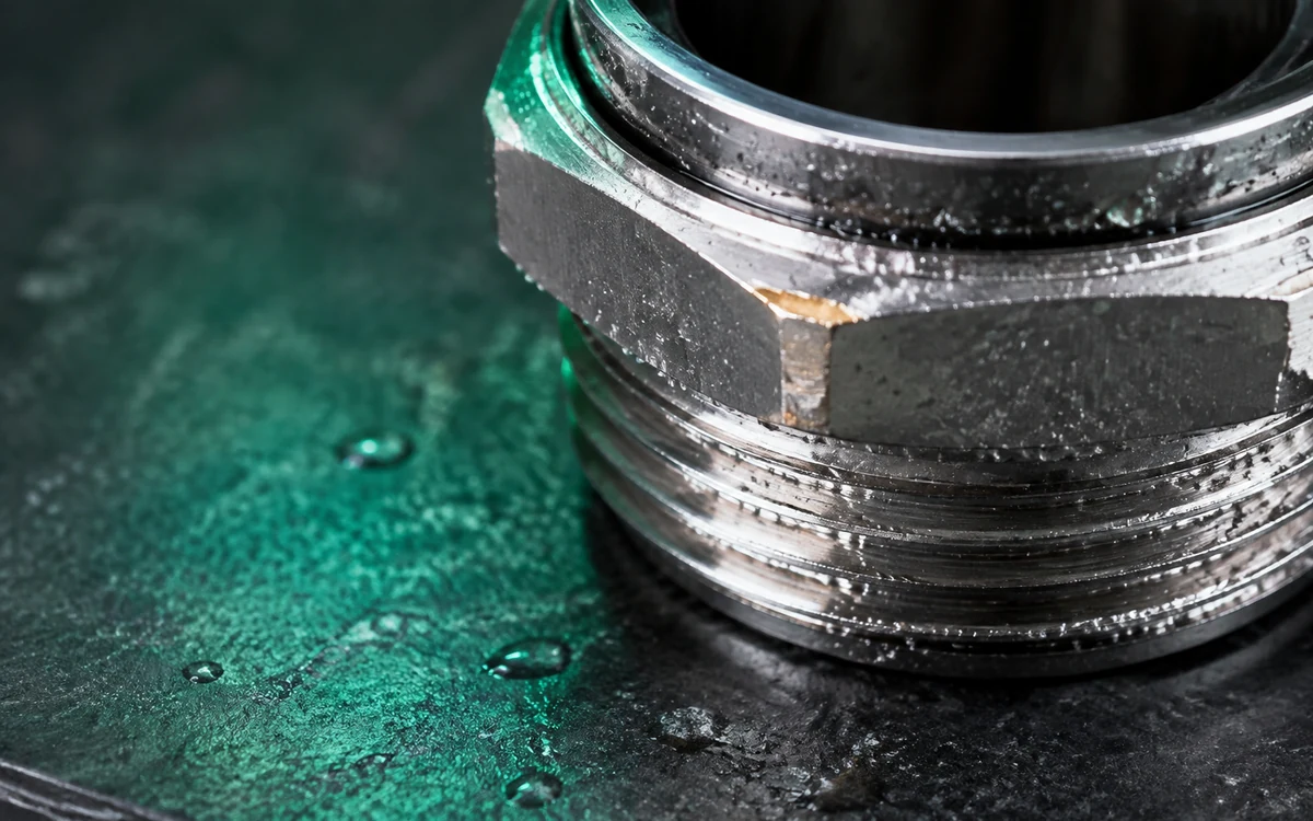
Determine whether the affected location contributes to sealing, thread engagement or electrical contact. Then assess defect depth, corrosion products and substrate condition using the component’s inspection and service criteria.
Match the finish to moisture, chemicals and wear
Coating selection depends on the substances and physical conditions that reach the gland. I compare temperature, concentration, contact time, cleaning, abrasion and mating materials. Marine air, alkaline washing, solvent contact and condensation create different demands. Even on one machine, a sheltered thread recess and an exposed upper face can experience different wetting and deposits.
| Exposure feature | Effect on the surface | What to assess |
|---|---|---|
| Condensation and wet-dry cycling | Creates intermittent electrolyte films | Where water forms, drains, and remains |
| Chloride or process deposits | Changes electrolyte chemistry in sheltered areas | Contaminant, deposition route, cleaning, and residue |
| Cleaning or process chemicals | Depends on identity, concentration, heat, and duration | Liquid, mixture, contact, rinse, and drying sequence |
| Abrasion and tool contact | Can break the barrier at edges and threads | Assembly method, access, adjustment, and used condition |
| Temperature changes | Affect metal, seals, interfaces and condensation | Temperature history and each component’s limits |
| Dissimilar-metal contact | Can create a galvanic path through electrolyte | All connected metals, coatings, and wetted areas |
I use the application-environment material guide to define the full material set before the finish. Select a compatible brass alloy, seal and mating-metal combination, then choose the finish for that material system.
Worked example: the same finish in two wetting conditions
Consider two hypothetical glands with the same coating. One sees occasional condensation that drains and dries. The other sits beneath a washer where chloride-bearing wash residue remains wet. I would examine the second location for retained deposits, a restricted drying path and damage at the contact edge. The useful response may include a different compatible material system or changes to the permitted cleaning and drainage arrangement. Compare representative exposed and sheltered features under the relevant wetting cycle before choosing between them. Local liquid chemistry and wetting time explain why the same finish can behave differently.
Combine surface protection with the gland’s working functions
Surface condition works with the body, seals, cable and entry to determine gland performance. IEC 62444:2010 covers complete glands as supplied. I check the coating at the interfaces that matter to each function, then assess the complete configuration for sealing, retention and its assigned electrical duty.
| Function | Relevant surface condition | Complete-gland assessment |
|---|---|---|
| Corrosion resistance | Coverage, adhesion and defects | Mating metals, wetting, damage and maintenance |
| Mechanical strength | Surface wear and damage at working contacts | Brass alloy, geometry, threads, load path and gland test |
| Ingress protection (IP) | Condition of metal beside a seal | Cable, seal, entry, washer, enclosure, assembly, and ingress test |
| Hazardous-area suitability | Defined material or surface condition | Certified gland, protection concept, marking, conditions, cable, and installation |
| Bonding or electromagnetic compatibility (EMC) | Condition of one contact surface | Whole path, pressure, mating finish, corrosion products, duty, and method |
| Temperature or chemical range | Tested deposit-substrate response | Seal, cable, lubricant, accessories, sequence, and limiting component |
| Service life | Behavior during one controlled test | Field exposure, damage, maintenance, failure rule, and correlation |
I review ingress through the IEC 60529 cable-entry guide, where IP applies to the tested enclosure. Screen or protective-bonding duties need the whole path in the electrical bonding framework. For hazardous-area use, the hazardous-area gland selection guide covers certification and installation. Keep the coating compatible with those installation requirements, including the intended conductive contact surfaces.
Use coating tests to compare the relevant property
I choose each coating test for the property at issue. Local thickness measures deposit quantity; adhesion tests challenge the bond. Porosity tests reveal through-defects, while salt fog compares behavior in a controlled corrosive exposure. Combine those findings with the actual component geometry and handling condition. Complete-gland tests then assess the functions that depend on the assembled product.
ASTM B117-26a defines salt-spray apparatus operation. Use it to compare responses of specified specimens with the same exposure and evaluation criteria. The standard calls for corroborating long-term atmospheric exposure before considering service extrapolation. The ASTM B117 cable-gland guide explains specimen preparation and comparison.
Before comparing results, match the brass, surface preparation, deposit, shape and handling. Use the same chamber conditions, duration, observation intervals, endpoint and sample count. An endpoint is the stated condition used to judge a test result. Record what failed: nickel staining, brass corrosion, blisters, pores or loss of function. Judge the feature that matters in service.
Protect the finish during assembly and service
Care during assembly and service helps preserve the finish. I check tool-contact flats, entry threads, seal lands and washer edges. Use the specified tools and assembly method, remove debris by an approved cleaning method, and avoid dragging damaged mating threads across the plated surface.
Before loosening or removing a gland, follow the equipment’s isolation and maintenance procedure. Inspect coating loss, pits, blisters and deposits where the part actually becomes wet or carries load. A damaged sealing land needs a sealing assessment; a degraded bonding contact needs the relevant electrical check. Follow the permitted repair or replacement method. Coating work must preserve thread fit, seals and required contacts.
The cable-gland corrosion diagnosis guide helps distinguish deposits, staining, pits, blisters and coating loss. Branching cracks require a separate assessment of the brass, loading and environment, as described in the brass stress-corrosion cracking guide. Record the affected feature and operating conditions so recurring damage can be traced to exposure, handling or the material choice.
Conclusion
Nickel-plated brass improves the working surface when the layer stays bonded, covers the brass and suits the exposure. I choose it by comparing the brass and coating together, then checking the actual faces, edges, threads and interfaces that perform the work.
Use local thickness, adhesion, porosity and exposure tests for the decisions they address. Preserve the finish during assembly, and investigate damage where moisture and deposits accumulate. A well-matched surface system supports the complete gland, whose seals, retention, temperature range and electrical functions still need to suit the installation.
FAQs about nickel-plated brass cable glands
What does nickel plating contribute to a brass cable gland?
It provides an exposed surface that can act as a corrosion barrier and, with an appropriate deposit, provide specified wear or hardness properties. The useful benefit depends on preparation, adhesion, coverage and exposure. I assess the finish at the working features alongside the brass body, seals and complete-gland requirements.
How does nickel plating relate to IP or hazardous-area performance?
Coating condition is one part of the complete entry arrangement. For ingress protection (IP), check the cable, seal, entry, washer, enclosure and assembly under the relevant test conditions. For hazardous-area use, follow the exact certified product, protection concept, marking and installation conditions. Keep the finish compatible with those requirements and interfaces.
How should a scratch in nickel plating be assessed?
Check its depth, location and exposure. A scratch that reaches brass or an intermediate layer creates a path for liquid and deposits to contact that metal. Damage at a seal land, thread or electrical contact also needs the corresponding functional assessment. Use the product’s service criteria to decide on repair or replacement.
When is nickel-plated brass suitable for marine or chemical service?
Use it where the complete material system is compatible with the actual medium, concentration, temperature and contact history. Include wet-dry cycles, retained deposits, cleaning, abrasion, mating metals and seals. Compare representative features in those conditions, especially sheltered areas and damaged edges, when selecting the coating and planning inspection.
What makes two nickel-plated brass cable glands technically comparable?
Compare brass alloy, condition, geometry, deposit process, intermediate layers, local thickness and significant surfaces. Then align exposure, handling, specimen preparation and the test endpoint. I also check the same cable, seal and entry arrangement for complete-gland functions. This keeps the material comparison connected to the installation where the gland will be used.
Sources and technical references
- ASTM B689-97(2023) - Standard Specification for Electroplated Engineering Nickel Coatings, accessed 2026-10-28.
- ASTM B571-23 - Standard Practice for Qualitative Adhesion Testing of Metallic Coatings, accessed 2026-10-28.
- ASTM B568-98(2021) - Standard Test Method for Measurement of Coating Thickness by X-Ray Spectrometry, accessed 2026-10-28.
- ASTM B765-03(2023) - Standard Guide for Selection of Porosity and Gross Defect Tests for Electrodeposits and Related Metallic Coatings, accessed 2026-10-28.
- ASTM B809-25 - Standard Test Method for Porosity in Metallic Coatings by Humid Sulfur Vapor, accessed 2026-10-28.
- NASA SP-8088 - Liquid Rocket Metal Tanks and Tank Components, accessed 2026-10-28.
- IEC 62444:2010 - Cable glands for electrical installations, accessed 2026-10-28.
- ASTM B117-26a - Standard Practice for Operating Salt Spray Fog Apparatus, accessed 2026-10-28.