

Cable glands contribute to short circuit protection through cable-entry protection and, where assigned, a connection in the protective return path. The fuse or circuit breaker performs the interruption. I identify the gland’s duty from the actual return path. A separate protective conductor and armour used for protection place different demands on the entry. BS 7671 coordinates the cable, connections and protective device for that circuit.
Key takeaways
- Protect the cable from entry-edge damage, excessive movement and unsupported loads.
- Trace the protective return path and identify every gland contact that it uses.
- Check steel-wire armour for its assigned protective duty, including thermal capability and both end terminations.
- Coordinate the complete circuit with the protective device; inspect sealing and EMC functions separately.
- Use BS 7671:2018+A4:2026 for current new work, with the installation’s applicable requirements and verification method.
How cable glands contribute to short circuit protection
Short-circuit protection limits the harmful effects of fault overcurrent by interrupting it within the required conditions. IEC 60364-4-43:2023 addresses overcurrent protection and coordination, with automatic disconnection as the preferred protective measure. A gland supports that installation through its cable-entry functions; the protective device has the operating mechanism that opens the circuit.
The fault location determines which path matters. A line-to-neutral short circuit returns through the neutral. A fault from a line conductor to an exposed metal enclosure can involve the protective-conductor system. For the latter, the return path and device response are also part of protection against electric shock, addressed by IEC 60364-4-41:2005+A1:2017. I identify the fault before deciding whether the gland carries any of its current.
A circuit protective conductor (CPC) connects the relevant exposed conductive parts to the protective earthing arrangement. The fault loop is the complete route through the source, the line conductor to the fault and the return path back to the source. A metallic gland may provide one connection within that loop. Its contribution depends on where the conductors and contacts are connected, not simply on the body material.
A damaged cable can initiate a fault; a poor protective contact can impair the response. Check gland selection and protective-device coordination together. The protective-path guide explains the grounding and bonding foundation in more detail.
Follow the protective path through the entry
The electrical duty of a gland follows the installed current path. Trace the fault from the exposed conductive part through its assigned CPC or permitted armour route to the source. Include any gland body, earth tag, bonding lead, threaded entry, locknut or gland plate that the route actually crosses. A painted surface, insulating washer or removable panel deserves attention wherever it separates two intended contacts.
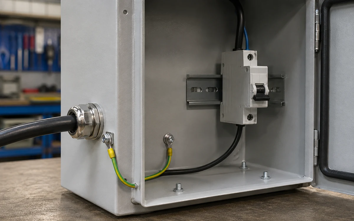
An earth tag is a bonding accessory with a conductor connection point, used within a compatible gland assembly. That conductor must reach the intended protective connection. A tag with no effective connection at its other end adds no useful return route. Likewise, a locknut secures the entry mechanically, while its electrical role depends on the contact arrangement and the design.
Worked example: separate CPC through a polymer gland
Consider a hypothetical cable containing line, neutral and a separate CPC, entering a metal enclosure through a polymer gland. The CPC terminates at the enclosure’s designated protective connection. For a line-to-enclosure fault, the intended return uses that connection and the CPC. The gland protects and retains the cable while the conductor carries the assigned protective current. I check both jobs: correct cable fit and support at the entry, then sound CPC termination and the complete protective arrangement. Choosing a metal gland instead would not remove the need to connect the CPC correctly. A CPC left unconnected at the enclosure defeats this arrangement even if the gland grips the cable securely. Inspect the CPC conductor, terminal and enclosure connection as well as the entry.
Worked example: armour assigned as the CPC
Now consider a design that uses steel-wire armour as the CPC. The route may depend on the armour contact, gland body and a specified enclosure or bonding connection at each end. The IET’s earthing and bonding FAQ explains that armour suitability requires calculation with the steel’s thermal constraints taken into account. Check the actual cable construction, armour area, fault duty and protective-device response, then match both terminations to that design. A loose armour clamp can affect the protective path even while the outer seal continues to grip the jacket. I trace both ends and any parallel route before interpreting a continuity result. Another connected cable or metal structure can bypass the joint being checked. The fault-path diagnosis guide explains how to locate open joints and distinguish intended connections from such bypasses.
Why joint resistance changes the protective response
Earth-fault loop impedance is the opposition to current around the complete earth-fault loop. Where a fuse or circuit breaker provides fault protection, a higher loop impedance reduces the available fault current and can change its operating time. I therefore treat a gland contact as part of the circuit calculation when the protective path uses it, rather than assessing its resistance in isolation.
The IET’s 2025 guidance on verification and unnecessary live testing explains the relationship between loop impedance and protective-device operation. It also describes how parallel paths can conceal an ineffective intended connection. Use the current installation requirements and the selected device’s characteristics for the acceptance decision; that article was written against Amendment 3.
Worked example: an added resistive joint
For a simple hypothetical TN fault-loop comparison, assume a fixed 230 V supply and treat the loop as entirely resistive. Ohm’s law gives:
Here, is fault current in amperes, is the assumed voltage in volts, and is total loop resistance in ohms. Keep the rest of the loop unchanged.
| Illustrative condition | Total loop resistance | Calculated current |
|---|---|---|
| Original assumed loop | 0.40 Ω | 230 / 0.40 = 575 A |
| An assigned gland joint adds 0.20 Ω | 0.60 Ω | 230 / 0.60 ≈ 383 A |
The added resistance reduces the calculated current by about one third. The next question is where each current lies on the protective device’s operating characteristic. These assumed values are a comparison, not pass/fail limits or a measured installation. An actual assessment uses the relevant impedance, voltage conditions, conductor temperature and protective-device requirements; it also checks thermal duty. RCD fault protection has a different operating basis and needs the checks appropriate to that arrangement.
Restore the specified contact arrangement and verify the circuit. Overtightening can damage the cable, thread or contact. Use the selected gland’s assembly instructions and address paint, corrosion, loose contacts or missing connections through the approved installation method.
Use mechanical protection and cable support together
Cable retention resists the cable movement assigned to the gland’s grip. External support carries loads assigned to clamps, cleats or other supports along the cable route. Both matter at the enclosure: a well-gripped cable can still bend sharply under its own weight, and a supported cable can still have the wrong diameter for the seal.
I check the entry as a physical assembly. Match the jacket and any armour or bedding dimensions to their respective ranges. Keep the cable aligned as it enters the gland, protect it from sharp edges, and arrange support so weight and pull do not reach terminals through the entry. Allow for the specified bend radius and movement. These measures reduce conditions that can damage insulation or disturb connections.
IEC 62444:2010 addresses construction and performance of complete glands as supplied. Apply the relevant declared retention and assembly information to the selected cable and entry. The IEC 62444 selection guide develops those product checks.
Movement at an armour termination can disturb its contact as well as the cable position. After correcting a support problem, inspect the affected termination and carry out the verification required by the installation procedure. Keep the work safely isolated before disturbing the entry or its protective connections.
Match sealing, EMC and protective-current duties separately
A seal closes an ingress route; an armour clamp grips the specified armour; a protective connection carries fault current. I identify the surfaces serving each purpose so a change for one function preserves the others.
| Entry function | Useful contribution | What to check at the installation |
|---|---|---|
| Cable retention | Holds the specified cable against assigned movement | Cable dimensions, grip assembly and external supports |
| Armour termination | Secures armour and may carry protective current | Armour construction, contact arrangement, both ends and fault duty |
| Protective connection | Joins the intended conductive parts into the return path | Each contact, bonding conductor, enclosure joint and source return |
| Environmental sealing | Closes the cable-facing or entry-wall ingress route | Seal material, cable surface, entry face and the complete enclosure |
| EMC termination | Connects the screen through the intended high-frequency interface | Screen construction, contact geometry and system EMC requirements |
IEC 60529 classifies enclosure protection against access and ingress. Match the IP result to the actual enclosure boundary, including the gland, cable and entry seal. Also consider moisture from condensation or another enclosure opening when choosing environmental controls. The IEC 60529 cable-entry guide explains that complete boundary.
An EMC screen contact can share metal parts with a protective connection, but the two duties use different criteria. High-frequency shielding depends on termination geometry; protective-current duty depends on the assigned path and fault conditions. Check both when the design assigns both functions to one assembly. Similarly, a gasket added for sealing may change the intended contact between a gland and a metal wall, so use the specified sealing and bonding arrangement together.
Apply the current BS 7671 requirements to the circuit
The IET’s current edition-status page identifies BS 7671:2018+A4:2026 as the current edition. The preceding Amendment 2 transition ended on 15 October 2026. For new installation work and specifications, use Amendment 4 and its applicable corrections. Check existing installations against the requirements relevant to the work and their actual condition; a new edition is not a substitute for that assessment.
I use the circuit design to connect the gland checks with the protective measure:
- Locate the fault being assessed. Identify the exposed conductive parts, earthing arrangement, source and protective device.
- Trace the return path. Include the assigned CPC or armour and every entry or enclosure contact that it uses.
- Check the electrical duty. Coordinate loop conditions, conductor thermal capability and the protective-device response using the applicable requirements.
- Inspect the entry assembly. Match cable construction, component ranges, accessories, enclosure surfaces and external support to the installation instructions.
- Verify the completed arrangement. Use the specified inspection and test method, accounting for parallel paths and the points actually tested.
Choose the verification method before opening a connection. The IET guidance on minimizing live testing explains how suitable dead tests and circuit calculations can reduce unnecessary access to live terminals. Electrical work also has legal duties: the HSE electricity-law page identifies the Electricity at Work Regulations and other potentially applicable legislation. Use competent personnel and the site’s safe-isolation procedure for work on the gland or protective connections.
Conclusion
Cable glands contribute by protecting the cable physically and maintaining any protective connection assigned to the entry. I first trace the fault path: a separate CPC can bypass the gland body, while an armour-based route can depend on the gland contacts at both ends. That difference determines the electrical checks the entry needs.
Then coordinate the complete path with the protective device and check cable fit, support and sealing on the installed assembly. For current new work, use BS 7671:2018+A4:2026. A sound entry combines these functions so cable movement, damaged insulation or a poor contact does not undermine the circuit’s protective arrangement.
FAQs about cable glands and short-circuit protection
Can a cable gland replace a fuse or circuit breaker?
The fuse or circuit breaker interrupts the fault current; the gland supports cable protection and any assigned protective connection. Select the gland for its cable, entry and contact duties, then coordinate the circuit with the protective device. Its sealing or retention rating describes a different function from the device’s operating characteristic.
When does a metal cable gland carry protective current?
It carries protective current when the designed return route passes through its contacts, such as an armour termination connected to a metal enclosure or bonding lead. Trace those connections through to the source and check their assigned duty. With a separate CPC, the intended protective route may bypass the gland body entirely.
Can steel-wire armour be used as the CPC through a gland?
Yes, when the design permits it and the actual armour meets the protective duty, including thermal constraints. Check the cable construction, armour area, fault conditions, protective-device response and terminations at both ends. Select and assemble the gland for that armour so the intended contact is maintained throughout the route.
What does an IP rating contribute to cable-entry protection?
An IP rating describes protection provided by the enclosure boundary against access and ingress under the applicable conditions. Use the correct gland, cable and entry seal to maintain that boundary. Check the protective-current path separately, and include other moisture routes such as condensation in the environmental review where they are relevant.
How should a continuity test across the gland be interpreted?
Relate the result to the actual test points, connection state and possible parallel paths. A low reading through a bypass can hide a defective intended joint. Combine the specified continuity checks with the circuit’s conductor, loop and device assessment, using the verification method and acceptance criteria applicable to the installation.
Sources and technical references
- IET — Ensure you are up to date with BS 7671, accessed 2026-10-28.
- IET — Earthing and bonding FAQs, accessed 2026-10-28.
- IET Wiring Matters — Minimizing unnecessary live testing for initial verification, May 2025, accessed 2026-10-28.
- IEC 60364-4-43:2023 — Protection against overcurrent, accessed 2026-10-28.
- IEC 60364-4-41:2005+AMD1:2017 CSV — Protection against electric shock, accessed 2026-10-28.
- IEC 62444:2010 — Cable glands for electrical installations, accessed 2026-10-28.
- IEC 60529:1989+AMD1:1999+AMD2:2013 CSV — Degrees of protection provided by enclosures, accessed 2026-10-28.
- HSE — Electricity and the law, accessed 2026-10-28.