# 依有限元素分析，電纜密封接頭的關鍵應力集中位置在哪裡？

> Source: https://chinacableglands.com/zh-hant/blog/where-are-the-critical-stress-points-in-cable-glands-according-to-fea-analysis/
> Language: zh-Hant
> Publisher: 倍拓電纜接頭
> Author: Edward Wang
> Published: 2026-02-03
> Updated: 2026-10-29

找出電纜密封接頭最可能產生應力集中的區域，再將各項有限元素分析結果連結至實際負荷路徑、組裝條件及實體測試。

<p><strong>電纜接頭的主要應力區域包括受載的入口螺紋及退刀區、本體轉折處、密封件或夾具邊緣、電纜出口，以及外殼安裝處。</strong>哪個區域會成為控制部位，取決於力如何經由已安裝的電纜、接頭與牆板傳遞。我會先追蹤這條載荷路徑，再使用有限元素分析（FEA）檢視承受載荷的零件與接觸面。</p>
<p>有用的模型應回答具體的設計問題：較大的圓角是否能降低局部應變、彎曲是否會使部分密封面張開，或較薄的安裝面板是否會產生足以擾動接合處的彈性變形。所需的輸出應由問題決定。金屬應力、密封壓力與電纜移動代表不同的反應。</p>
<blockquote>
<p><strong>重點摘要</strong></p>
<ul>
<li>從受載電纜層開始，沿力的傳遞路徑追蹤至接頭，再進入外殼。</li>
<li>施加使用載荷前，先納入組裝預緊力。</li>
<li>在局部反應重要之處，解析螺紋牙底、圓角與接觸邊緣。</li>
<li>彎曲使高應力區移動時，檢查電纜支撐與牆板剛度。</li>
<li>將數值穩定的結果量與同一組件上的量測值比較。</li>
</ul>
</blockquote>
<h2 id="where-should-a-cable-gland-fea-review-begin">電纜接頭的有限元素分析應從何處開始？</h2>
<p><strong>有限元素分析</strong>以相互連接的小型元素表示幾何，再求解其在指定材料、載荷、接觸狀態與約束條件下的反應。<strong>應力集中</strong>是與幾何變化或載荷傳遞變化相關的局部應力升高。電纜入口包含數個此類變化，因此我會先檢視完整的已安裝接合處，再選擇較小區域進行詳細分析。</p>
<p>從夾持或夾具接觸的電纜層追蹤載荷。載荷經過接頭本體與入口連接處，傳入外殼及其支撐結構。載荷可能跨越滑動介面、彈性體或鎧裝電纜夾具。黏結接觸假設可能抑制真實接合處中會發生的移動。</p>
<table>
<thead>
<tr>
<th>檢視區域</th>
<th>實際原因</th>
<th>有助於說明原因的結果</th>
</tr>
</thead>
<tbody>
<tr>
<td>受載的螺紋牙側、牙底與退刀區</td>
<td>載荷透過較小的輪廓分配，且方向會改變</td>
<td>螺紋牙面間的載荷分配、局部應變與接合處張開</td>
</tr>
<tr>
<td>本體肩部、底切部與壁面轉折處</td>
<td>截面與剛度變化</td>
<td>應力／應變分布與永久變形</td>
</tr>
<tr>
<td>密封邊緣與密封帶</td>
<td>組裝變形形成接觸</td>
<td>壓力分布、接觸寬度與分離</td>
</tr>
<tr>
<td>電纜夾持部或鎧裝夾具</td>
<td>載荷進入特定電纜層</td>
<td>滑移、電纜層移動與接觸載荷</td>
</tr>
<tr>
<td>電纜出口</td>
<td>柔性電纜接觸剛性邊界</td>
<td>彎曲應變與局部電纜曲率</td>
</tr>
<tr>
<td>面板、墊圈、鎖緊螺母或內螺紋凸台</td>
<td>安裝零件閉合載荷路徑</td>
<td>面板撓曲、承壓與入口轉動</td>
</tr>
</tbody>
</table>
<p>設定接觸關係前，先確認電纜結構。<a href="/zh-hant/blog/armored-vs-unarmored-cable-glands-which-one-do-you-really-need/">鎧裝與非鎧裝的比較</a>說明了為何鎧裝夾具與外被夾持部會透過不同層傳遞作用力。用於電磁相容性（EMC）的屏蔽接觸，還需要另行指定其機械作用。</p>
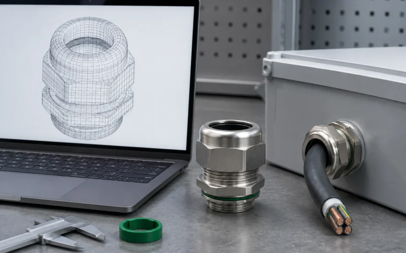
<img alt="筆記型電腦畫面顯示未標註的接頭線框圖，旁有單獨的接頭、已裁切電纜、外殼引入口及卡尺。" src="/images/blog/where-are-the-critical-stress-points-in-cable-glands-according-to-fea-analysis/fea-model-review-workstation.webp" srcset="/images/blog/where-are-the-critical-stress-points-in-cable-glands-according-to-fea-analysis/fea-model-review-workstation.webp 800w" sizes="(max-width: 800px) 100vw, 800px" width="800" height="500" loading="lazy" decoding="async">
<p><em>工作台上並列放置電纜密封接頭樣品、外殼引入口、卡尺及未標註的線框模型。</em></p>
<h2 id="choose-the-load-cases-before-refining-the-mesh">細化網格前先選定載荷工況</h2>
<p><strong>預載荷</strong>是組裝時產生的初始力或變形。鎖緊可以在任何外部拉力發生前建立螺紋接觸、使肩部就位並壓縮密封件。我會先求解或以其他方式表示此組裝狀態，再依問題套用適當的使用載荷順序。</p>
<p>軸向拉力、側向力、壓力與熱位移可能沿不同路徑作用。振動會帶來隨時間變化的反應；溫度也可能改變材料行為與初始過盈量。每個工況都要保留方向、載荷施加面積及外部支撐位置，才能在相同基準下比較後續的變體。</p>
<table>
<thead>
<tr>
<th>載荷工況</th>
<th>應保留的組裝細節</th>
<th>優先檢視的反應</th>
</tr>
</thead>
<tbody>
<tr>
<td>軸向電纜拉力</td>
<td>正確的夾持層與電纜支撐</td>
<td>滑移與傳遞至本體的力</td>
</tr>
<tr>
<td>出口處彎曲</td>
<td>電纜剛度、載荷方向與彎曲載荷施加點至入口的距離</td>
<td>單側張開、應變與面板轉動</td>
</tr>
<tr>
<td>鎖緊</td>
<td>接觸摩擦、閉合方式與工具反力</td>
<td>各接合處的預載荷與就位</td>
</tr>
<tr>
<td>內部壓力</td>
<td>受壓表面與密封狀態</td>
<td>分離、擠出與壁面反力</td>
</tr>
<tr>
<td>溫度變化</td>
<td>零件膨脹與溫度相依性質</td>
<td>過盈量變化與接觸寬度</td>
</tr>
<tr>
<td>重複運動</td>
<td>循環歷程、約束與相關動態反應</td>
<td>應力／應變範圍與接觸變化</td>
</tr>
</tbody>
</table>
<h3 id="worked-example-compare-two-bending-moment-inputs">計算示例：比較兩個彎矩輸入值</h3>
<p>若某作用力距參考點的垂直距離為 <span class="article-math article-math-inline" data-latex="d"><span class="katex"><math xmlns="http://www.w3.org/1998/Math/MathML"><semantics><mrow><mi>d</mi></mrow><annotation encoding="application/x-tex">d</annotation></semantics></math></span></span>，則其力矩大小為 <span class="article-math article-math-inline" data-latex="M=F d"><span class="katex"><math xmlns="http://www.w3.org/1998/Math/MathML"><semantics><mrow><mi>M</mi><mo>=</mo><mi>F</mi><mi>d</mi></mrow><annotation encoding="application/x-tex">M=F d</annotation></semantics></math></span></span>。此處 <span class="article-math article-math-inline" data-latex="F"><span class="katex"><math xmlns="http://www.w3.org/1998/Math/MathML"><semantics><mrow><mi>F</mi></mrow><annotation encoding="application/x-tex">F</annotation></semantics></math></span></span> 的單位為牛頓，<span class="article-math article-math-inline" data-latex="d"><span class="katex"><math xmlns="http://www.w3.org/1998/Math/MathML"><semantics><mrow><mi>d</mi></mrow><annotation encoding="application/x-tex">d</annotation></semantics></math></span></span> 的單位為公尺，<span class="article-math article-math-inline" data-latex="M"><span class="katex"><math xmlns="http://www.w3.org/1998/Math/MathML"><semantics><mrow><mi>M</mi></mrow><annotation encoding="application/x-tex">M</annotation></semantics></math></span></span> 的單位為牛頓公尺。<a href="https://www1.grc.nasa.gov/beginners-guide-to-aeronautics/drag-balance-operation/">NASA Glenn 對力矩的說明</a>提供此力與距離的關係。</p>
<p>考慮兩種<strong>假設載荷配置</strong>，每種都在電纜入口傳遞 80 N 橫向力。A 的作用力作用線距所選入口參考點 100 mm；B 則距 40 mm。這些是為靜態比較刻意選定的輸入值，並非模擬出的電纜接頭性能。</p>
<table>
<thead>
<tr>
<th>配置</th>
<th style="text-align: right">垂直距離</th>
<th style="text-align: right">參考點處計算出的彎矩</th>
</tr>
</thead>
<tbody>
<tr>
<td>A</td>
<td style="text-align: right">0.100 m</td>
<td style="text-align: right">80 × 0.100 = 8.0 N·m</td>
</tr>
<tr>
<td>B</td>
<td style="text-align: right">0.040 m</td>
<td style="text-align: right">80 × 0.040 = 3.2 N·m</td>
</tr>
</tbody>
</table>
<p>依此計算，我得到 B 的彎矩比 A 低 60%，而橫向力仍為 80 N。當載荷轉移至該參考點時，模型仍須施加此力與相應彎矩。如果實際電纜路徑或支撐也會改變力，應計算新的力分布，不要沿用這個假設值。</p>
<p>這項比較有助於選擇載荷工況與支撐幾何，但不會提供容許應力，也不能證明某個支撐間距合適。選擇已安裝的配置時，還要納入電纜彎曲限制、支撐剛度與接合處的實際反應。</p>
<h2 id="resolve-the-loaded-thread-and-body-transitions">解析受載螺紋與本體轉折處</h2>
<p><strong>螺紋接合長度</strong>是已就位組裝中能傳遞載荷的配合螺紋重疊長度。<strong>螺紋退刀區</strong>是完整螺紋牙型終止的位置。<strong>圓角</strong>是表面之間的圓弧轉折。當問題涉及螺紋應變或本體轉折處的高應力區時，這些特徵需要局部細節。</p>
<p>應使用實際組裝後的螺紋嚙合長度，而不是可見的外螺紋突出量。面板厚度、沉孔、墊圈、鎖緊螺母與轉接頭，都會影響哪些螺紋參與嚙合，以及肩部在哪裡就位。<a href="/zh-hant/blog/what-does-m20-cable-gland-actually-mean-a-spec-breakdown/">M20 規格指南</a>有助於確定這些尺寸輸入值。</p>
<p>檢查載荷分配時，我會納入配合零件的剛度、摩擦與預載荷。對於使用間隙孔的薄面板，應建立肩部、入口密封件、壁面與鎖緊螺母之間的接觸模型。對於攻有螺紋的凸台，應建立相關內螺紋及其支撐材料的模型。將切面完全固定，可能會使安裝結構比實際情況硬得多。</p>
<p>在本體轉折處，應保留實際製造的圓角半徑與壁厚。使用相同的施加載荷與安裝假設比較修改後的圓角，再檢查此改動是否也影響密封空間、工具操作空間或螺紋長度。只有在整體設計仍可用的前提下，局部應力改善才有意義。</p>
<h3 id="separate-a-stress-concentration-from-a-singularity">區分應力集中與奇異點</h3>
<p><strong>應力奇異點</strong>是模型中理想化的局部位置，其應力會持續增大而沒有有限上限。數學上的尖角或點約束可能造成這種行為。<a href="https://www.nafems.org/publications/knowledge-base/the-importance-of-mesh-convergence-part-1/">NAFEMS 的網格收斂指引</a>說明，零半徑內角會使網格細化時應力持續升高，也說明實際製造的圓角半徑為何重要。</p>
<p>峰值若持續升高，在將其視為實際失效預測前，應先檢查該處的幾何與邊界條件。如果局部應力是設計問題，就以實際半徑或承載面積建模。若研究的是其他問題，則應定義適當的路徑、面積或位移輸出，並證明其數值穩定性。不同變體之間須使用相同的評估定義。</p>
<h2 id="read-seal-contact-and-cable-retention-separately">分別檢視密封接觸與電纜固定</h2>
<p><strong>接觸壓力</strong>是跨越介面傳遞的壓縮作用。檢視密封件時，應確認接觸位置、接觸寬度及其如何隨載荷改變。<strong>von Mises 應力</strong>將金屬的應力狀態合併為一個純量，常用於延性材料降伏評估。金屬應力輪廓與密封接觸圖回答的是不同問題。</p>
<p>我會一併檢視密封件的變形、壓力與應變結果。一處有邊緣峰值而另一處張開，與形成連續受壓密封帶的情況可能有不同表現。模型應納入實際密封件輪廓、電纜直徑與形狀、組裝閉合狀態，以及適用的彈性體行為。若要代表預期使用狀態，溫度與隨時間發生的應力鬆弛也可能很重要。</p>
<p><a href="/zh-hant/blog/why-is-cold-flow-critical-in-cable-gland-seals-and-how-can-you-prevent-it/">密封件冷流指南</a>說明為何接觸狀態可能在組裝後改變。研究時間相依問題時，應使用相關材料資料與載荷歷程。接著，將模型預測的接觸反應與所代表組件的實測密封功能比較。</p>
<p>在電纜固定介面，追蹤電纜的相對移動及承載的電纜層。外被可能相對於內部構件移動；鎧裝設計則有自己的夾具與準備尺寸。<a href="/zh-hant/blog/how-do-cable-glands-balance-strain-relief-and-sealing-for-maximum-protection/">密封與電纜應力消除指南</a>有助於區分外部電纜支撐、夾持與環境密封。</p>
<figure class="blog-chart" style="container-type: inline-size;">
<svg id="fea-stress-map" xmlns="http://www.w3.org/2000/svg" viewBox="0 0 480 1680" role="img" aria-labelledby="fea-hotspot-title fea-hotspot-desc" style="display:block;width:100%;max-width:100%;height:auto;font-family:var(--font-body); width: 100% !important; max-width: 100% !important; height: auto !important;">
<style>
#fea-stress-map { --svg-body-screen: 17px; }
@media (max-width: 760px) { #fea-stress-map { --svg-body-screen: 16px; } }
</style>
<title id="fea-hotspot-title">已安裝電纜密封接頭中的負荷案例與潛在應力區域</title>
<desc id="fea-hotspot-desc">電纜密封接頭與外殼壁面的剖視圖標出電纜接觸處、本體轉折、引入口螺紋及面板反作用位置。獨立卡片列出軸向拉力、出口彎曲、鎖緊扭矩及預緊力；軸向與彎曲案例可能使主要反應區域移動。應力、接觸壓力、位移及電纜移動是不同的輸出量。</desc>
<text x="240" y="44" text-anchor="middle" fill="var(--color-carbon)" font-size="26" font-weight="700" style="font-size: calc(22px * 480px / 100cqw) !important;">沿載荷路徑追蹤</text>
<text x="240" y="78" text-anchor="middle" fill="var(--color-graphite)" font-size="19" style="font-size: calc(var(--svg-body-screen) * 480px / 100cqw) !important;">改變負荷案例，並檢查其反應。</text>
<rect x="20" y="106" width="440" height="458" rx="18" fill="var(--surface-card)" stroke="var(--color-cloud)" stroke-width="3"/>
<text x="57" y="151" fill="var(--color-graphite)" font-size="19" style="font-size: calc(16px * 480px / 100cqw) !important;">電纜</text>
<text x="345" y="151" fill="var(--color-graphite)" font-size="19" style="font-size: calc(16px * 480px / 100cqw) !important;">面板</text>
<rect x="347" y="225" width="30" height="75" fill="var(--color-ash)" stroke="var(--color-carbon)" stroke-width="3"/>
<rect x="347" y="360" width="30" height="75" fill="var(--color-ash)" stroke="var(--color-carbon)" stroke-width="3"/>
<path d="M120 270H245L282 300H406V360H282L245 390H120Z" fill="var(--surface-card)" stroke="var(--color-carbon)" stroke-width="4"/>
<path d="M290 300l7 -6l7 6l7 -6l7 6l7 -6l7 6l7 -6l7 6l7 -6l7 6l7 -6l7 6l7 -6l7 6l7 -6l7 6 M290 360l7 6l7 -6l7 6l7 -6l7 6l7 -6l7 6l7 -6l7 6l7 -6l7 6l7 -6l7 6l7 -6l7 6l7 -6" fill="none" stroke="var(--color-primary)" stroke-width="2"/>
<rect x="377" y="282" width="6" height="18" fill="var(--color-ash)" stroke="var(--color-carbon)" stroke-width="2"/>
<rect x="377" y="360" width="6" height="18" fill="var(--color-ash)" stroke="var(--color-carbon)" stroke-width="2"/>
<rect x="383" y="282" width="19" height="18" fill="var(--surface-card)" stroke="var(--color-carbon)" stroke-width="3"/>
<rect x="383" y="360" width="19" height="18" fill="var(--surface-card)" stroke="var(--color-carbon)" stroke-width="3"/>
<rect x="340" y="287" width="7" height="13" fill="var(--color-primary)"/>
<rect x="340" y="360" width="7" height="13" fill="var(--color-primary)"/>
<rect x="155" y="292" width="34" height="18" fill="var(--color-primary)"/>
<rect x="155" y="350" width="34" height="18" fill="var(--color-primary)"/>
<path d="M52 330H423" fill="none" stroke="var(--color-carbon)" stroke-width="42" stroke-linecap="round"/>
<path d="M52 330H423" fill="none" stroke="var(--color-ash)" stroke-width="24" stroke-linecap="round"/>
<path d="M145 203V250L172 292M230 447V405L255 382M320 203V265L360 294M412 447L392 378" fill="none" stroke="var(--color-carbon)" stroke-width="3"/>
<circle cx="145" cy="183" r="20" fill="var(--color-primary)"/><text x="145" y="190" text-anchor="middle" fill="#fff" font-size="20" font-weight="700" style="font-size: calc(16px * 480px / 100cqw) !important;">1</text>
<circle cx="230" cy="467" r="20" fill="var(--color-primary)"/><text x="230" y="474" text-anchor="middle" fill="#fff" font-size="20" font-weight="700" style="font-size: calc(16px * 480px / 100cqw) !important;">2</text>
<circle cx="320" cy="183" r="20" fill="var(--color-primary)"/><text x="320" y="190" text-anchor="middle" fill="#fff" font-size="20" font-weight="700" style="font-size: calc(16px * 480px / 100cqw) !important;">3</text>
<circle cx="412" cy="467" r="20" fill="var(--color-primary)"/><text x="412" y="474" text-anchor="middle" fill="#fff" font-size="20" font-weight="700" style="font-size: calc(16px * 480px / 100cqw) !important;">4</text>
<text x="240" y="535" text-anchor="middle" fill="var(--color-graphite)" font-size="19" style="font-size: calc(var(--svg-body-screen) * 480px / 100cqw) !important;">模型中需檢視的四個區域。</text>
<text x="240" y="613" text-anchor="middle" fill="var(--color-carbon)" font-size="22" font-weight="700" style="font-size: calc(18px * 480px / 100cqw) !important;">說明負荷輸入</text>
<rect x="20" y="635" width="440" height="56" rx="12" fill="var(--surface-card)" stroke="var(--color-cloud)" stroke-width="2"/><text x="44" y="671" fill="var(--color-carbon)" font-size="20" style="font-size: calc(var(--svg-body-screen) * 480px / 100cqw) !important;">透過電纜施加軸向拉力</text>
<rect x="20" y="703" width="440" height="56" rx="12" fill="var(--surface-card)" stroke="var(--color-cloud)" stroke-width="2"/><text x="44" y="739" fill="var(--color-carbon)" font-size="20" style="font-size: calc(var(--svg-body-screen) * 480px / 100cqw) !important;">出口處彎曲或移動</text>
<rect x="20" y="771" width="440" height="56" rx="12" fill="var(--surface-card)" stroke="var(--color-cloud)" stroke-width="2"/><text x="44" y="807" fill="var(--color-carbon)" font-size="20" style="font-size: calc(var(--svg-body-screen) * 480px / 100cqw) !important;">接合處的鎖緊扭矩</text>
<rect x="20" y="839" width="440" height="56" rx="12" fill="var(--surface-card)" stroke="var(--color-cloud)" stroke-width="2"/><text x="44" y="875" fill="var(--color-carbon)" font-size="20" style="font-size: calc(16px * 480px / 100cqw) !important;">接觸處的組裝預緊力</text>
<text x="240" y="950" text-anchor="middle" fill="var(--color-carbon)" font-size="22" font-weight="700" style="font-size: calc(18px * 480px / 100cqw) !important;">比較反應區域</text>
<rect x="20" y="972" width="440" height="56" rx="12" fill="var(--surface-card)" stroke="var(--color-cloud)" stroke-width="2"/><text x="44" y="1008" fill="var(--color-carbon)" font-size="20" font-weight="700" style="font-size: calc(16px * 480px / 100cqw) !important;">1</text><text x="79" y="1008" fill="var(--color-carbon)" font-size="20" style="font-size: calc(16px * 480px / 100cqw) !important;">電纜接觸處或夾持部</text>
<rect x="20" y="1040" width="440" height="56" rx="12" fill="var(--surface-card)" stroke="var(--color-cloud)" stroke-width="2"/><text x="44" y="1076" fill="var(--color-carbon)" font-size="20" font-weight="700" style="font-size: calc(16px * 480px / 100cqw) !important;">2</text><text x="79" y="1076" fill="var(--color-carbon)" font-size="20" style="font-size: calc(16px * 480px / 100cqw) !important;">本體轉折圓角</text>
<rect x="20" y="1108" width="440" height="56" rx="12" fill="var(--surface-card)" stroke="var(--color-cloud)" stroke-width="2"/><text x="44" y="1144" fill="var(--color-carbon)" font-size="20" font-weight="700" style="font-size: calc(16px * 480px / 100cqw) !important;">3</text><text x="79" y="1144" fill="var(--color-carbon)" font-size="20" style="font-size: calc(16px * 480px / 100cqw) !important;">接合螺紋牙底</text>
<rect x="20" y="1176" width="440" height="56" rx="12" fill="var(--surface-card)" stroke="var(--color-cloud)" stroke-width="2"/><text x="44" y="1212" fill="var(--color-carbon)" font-size="20" font-weight="700" style="font-size: calc(16px * 480px / 100cqw) !important;">4</text><text x="79" y="1212" fill="var(--color-carbon)" font-size="20" style="font-size: calc(16px * 480px / 100cqw) !important;">墊圈與面板反作用處</text>
<text x="240" y="1285" text-anchor="middle" fill="var(--color-carbon)" font-size="22" font-weight="700" style="font-size: calc(18px * 480px / 100cqw) !important;">同一接合處，不同案例</text>
<rect x="20" y="1308" width="440" height="90" rx="14" fill="var(--surface-card)" stroke="var(--color-cloud)" stroke-width="2"/>
<text x="44" y="1344" fill="var(--color-carbon)" font-size="21" font-weight="700" style="font-size: calc(18px * 480px / 100cqw) !important;">軸向案例</text>
<text x="44" y="1375" fill="var(--color-graphite)" font-size="19" style="font-size: calc(var(--svg-body-screen) * 480px / 100cqw) !important;">檢查圓周方向的載荷分配。</text>
<rect x="20" y="1410" width="440" height="90" rx="14" fill="var(--surface-card)" stroke="var(--color-cloud)" stroke-width="2"/>
<text x="44" y="1446" fill="var(--color-carbon)" font-size="21" font-weight="700" style="font-size: calc(18px * 480px / 100cqw) !important;">彎曲案例</text>
<text x="44" y="1477" fill="var(--color-graphite)" font-size="19" style="font-size: calc(var(--svg-body-screen) * 480px / 100cqw) !important;">檢查接合處受載的一側。</text>
<text x="240" y="1550" text-anchor="middle" fill="var(--color-carbon)" font-size="22" font-weight="700" style="font-size: calc(18px * 480px / 100cqw) !important;">分別判讀各種輸出</text>
<rect x="20" y="1570" width="210" height="48" rx="10" fill="var(--color-ash)" stroke="var(--color-primary)" stroke-width="2"/><text x="125" y="1601" text-anchor="middle" fill="var(--color-carbon)" font-size="19" style="font-size: calc(16px * 480px / 100cqw) !important;">金屬應力</text>
<rect x="250" y="1570" width="210" height="48" rx="10" fill="var(--color-ash)" stroke="var(--color-primary)" stroke-width="2"/><text x="355" y="1601" text-anchor="middle" fill="var(--color-carbon)" font-size="19" style="font-size: calc(16px * 480px / 100cqw) !important;">接觸壓力</text>
<rect x="20" y="1628" width="210" height="48" rx="10" fill="var(--color-ash)" stroke="var(--color-primary)" stroke-width="2"/><text x="125" y="1659" text-anchor="middle" fill="var(--color-carbon)" font-size="19" style="font-size: calc(16px * 480px / 100cqw) !important;">位移</text>
<rect x="250" y="1628" width="210" height="48" rx="10" fill="var(--color-ash)" stroke="var(--color-primary)" stroke-width="2"/><text x="355" y="1659" text-anchor="middle" fill="var(--color-carbon)" font-size="19" style="font-size: calc(16px * 480px / 100cqw) !important;">電纜移動</text>
</svg>
<figcaption>示意圖標示了電纜接觸、本體轉折、已嚙合的入口螺紋與安裝反力。應為每個載荷工況建模，並檢查相關介面處的應力、接觸與移動。</figcaption>
</figure>
<h2 id="build-a-model-that-preserves-the-important-interfaces">建立能保留重要介面的模型</h2>
<p>我會依預期決策所需的詳細程度來指定模型。全域模型可用來確定面板移動與反力；詳細的局部模型則可透過一致的轉移邊界條件，檢視螺紋牙底或圓角。任一模型省略的幾何，都必須仍與所調查的反應相容。</p>
<p><a href="https://standards.nasa.gov/standard/nasa/nasa-std-7009">NASA-STD-7009B</a> 將建模實務與預期用途，以及 NASA 活動中明確定義的接受準則相連結。將此原則用於本建模問題時，表示應先就研究問題及有用的比較方式達成共識，再繪出結果。研究電纜入口時，應先商定所需輸出與比較準則，再評估各種變體。</p>
<p>每次修訂模型時，記錄以下輸入資料：</p>
<ol>
<li><strong>組裝：</strong>接頭變體、電纜層、入口、配件與圖面修訂版次。</li>
<li><strong>幾何：</strong>與問題相關的公差、圓角半徑、壁厚與簡化假設。</li>
<li><strong>材料：</strong>金屬與彈性體模型、溫度、調理條件與資料範圍。</li>
<li><strong>接觸：</strong>黏結、分離或滑動行為、摩擦與過盈量。</li>
<li><strong>組裝狀態：</strong>就位、預載荷及使用載荷前的密封閉合狀態。</li>
<li><strong>載荷與約束：</strong>大小、方向、作用面積、順序及實際治具或外殼支撐。</li>
<li><strong>輸出：</strong>結果量、位置、平均方式、單位與比較準則。</li>
</ol>
<figure>
<picture>
<source media="(max-width: 640px)" srcset="/images/blog/where-are-the-critical-stress-points-in-cable-glands-according-to-fea-analysis/gland-geometry-reference-probe-setup-600.webp">
<img alt="完整電纜密封接頭組件穿過面板試片夾持，配有獨立電纜支撐，以及接觸接頭本體與面板基準面的探頭。" src="/images/blog/where-are-the-critical-stress-points-in-cable-glands-according-to-fea-analysis/gland-geometry-reference-probe-setup.webp" width="1200" height="800" loading="lazy" decoding="async">
</picture>
<figcaption>配件堆疊、電纜支撐及探頭接觸點，顯示在組裝後的接合處量測幾何形狀與移動情形的位置。</figcaption>
</figure>
<h2 id="check-equilibrium-mesh-sensitivity-and-model-assumptions">檢查平衡、網格敏感度與模型假設</h2>
<p>從變形形狀與反力開始檢查。非預期的剛體移動表示可能缺少約束。若本體幾乎沒有移動而受測面板卻發生彎曲，則支撐模型可能需要調整。對於靜力平衡工況，確認施加的力與力矩是否與反力平衡。</p>
<p>例如，若<strong>假設的靜態模型</strong>沿一個方向施加 200 N，卻只得到總計 170 N 的反向反力，便有 30 N 尚未解釋。這相當於施加載荷的 15%。檢查輸出是否漏掉了某個支撐或其他力的貢獻、載荷步是否已收斂，以及預期工況是否確實為靜態。在使用應力圖比較設計前，先解決力的平衡問題。</p>
<p><strong>網格敏感度</strong>描述離散化加密時所選結果如何變化。加密相關區域，並在相同的實際位置比較相同結果量。使用符合決策需求的明確收斂準則。平均位移穩定，不代表局部接觸壓力峰值已獲充分解析。</p>
<p><strong>敏感度分析</strong>檢視輸入值或假設改變時輸出如何變化。我會在有依據的範圍內改變不確定的摩擦係數、電纜剛度、材料性質或安裝約束。若在合理的輸入值下首選設計會改變，應針對控制此選擇的輸入安排量測。這能指出哪些地方需要額外的實體資訊。</p>
<p><a href="https://standards.nasa.gov/sites/default/files/standards/NASA/A/0/nasa-hdbk-7009a.pdf">NASA-HDBK-7009A 詞彙表與指引</a>區分<strong>驗證</strong>、實證<strong>確效</strong>、敏感度與不確定性。驗證檢查實作與數值解；確效則在預期用途下將模型與實體系統比較。網格加密支持數值檢查；相符的量測則支持實體比較。</p>
<h2 id="compare-each-predicted-response-with-a-useful-measurement">將每項預測反應與有用的量測結果比較</h2>
<p>選擇能觀察模型相同載荷路徑的量測方式。荷重元可檢查施加的力，位移量測可追蹤面板或接頭移動，合適的應變量測則可比較可接近的本體區域。記錄感測器的位置與方向，讓模擬輸出能在對應位置進行評估。</p>
<figure>
<picture>
<source media="(max-width: 640px)" srcset="/images/blog/where-are-the-critical-stress-points-in-cable-glands-according-to-fea-analysis/lateral-load-path-observation-setup-600.webp">
<img alt="固定式電纜密封接頭彎曲治具，設有面板、電纜滾輪、側向鞍座、獨立電纜夾，以及接觸接頭本體與面板基準面的探頭。" src="/images/blog/where-are-the-critical-stress-points-in-cable-glands-according-to-fea-analysis/lateral-load-path-observation-setup.webp" width="1200" height="800" loading="lazy" decoding="async">
</picture>
<figcaption>受控程序開始前，先使側向負荷路徑與兩個觀察點對正。</figcaption>
</figure>
<table>
<thead>
<tr>
<th>建模問題</th>
<th>實體比較方式</th>
<th>可獲得的設計資訊</th>
</tr>
</thead>
<tbody>
<tr>
<td>入口或本體會在載荷下變形嗎？</td>
<td>載荷、位移、應變與永久變形檢查</td>
<td>局部剛度與載荷分布</td>
</tr>
<tr>
<td>彎曲會擾動密封嗎？</td>
<td>組裝移動、洩漏與試驗後的密封狀態</td>
<td>接觸變化與密封反應</td>
</tr>
<tr>
<td>電纜是否滑移或有電纜層受損？</td>
<td>施加拉力或扭轉載荷並記錄電纜移動</td>
<td>電纜保持力的傳遞路徑與滑移起始點</td>
</tr>
<tr>
<td>面板是否控制移動？</td>
<td>面板撓度與安裝接觸痕跡</td>
<td>壁板與治具剛度的影響</td>
</tr>
<tr>
<td>重複載荷會在哪裡造成損傷？</td>
<td>明確定義循環暴露條件並規劃檢查</td>
<td>相關位置與載荷歷程反應</td>
</tr>
</tbody>
</table>
<p><a href="https://www.asme.org/codes-standards/find-codes-standards/standard-for-verification-and-validation-in-computational-solid-mechanics">ASME V&amp;V 10-2019 (R2025)</a> 為計算固體力學中的驗證、確效與不確定性提供架構。我會運用比較結果，找出需要修正哪些模型輸入，以及結果對既定設計決策提供了多大支持。</p>
<p><a href="https://webstore.iec.ch/en/publication/7034">IEC 62444:2010</a> 在其適用範圍內規定完整電纜接頭的要求與試驗。分析時也應採用相關產品試驗與實際安裝條件。靜態應力結果只說明所建模的載荷工況；侵入防護、電纜固定與循環耐久性則各自需要符合其功能的評估。</p>
<h2 id="turn-the-hotspot-into-a-design-decision">將高應力區轉化為設計決策</h2>
<p>選擇能解決實際成因的改動。本體轉折處的應力集中可促使檢討圓角半徑或截面。密封接觸不均可促使調整輪廓、閉合方式或電纜配合。入口轉動可促使檢討安裝方式或面板剛度；出口彎曲則可促使改變電纜路徑或支撐。</p>
<p>我會使用相同的輸出定義與使用問題比較每次修訂。維持一致的組裝狀態，並重新檢查改動影響的相鄰介面。例如，較大的肩部可能提升安裝剛度，卻減少工具操作空間；改變密封腔也可能改變本體承受的閉合載荷。</p>
<h2 id="conclusion">結論</h2>
<p>電纜接頭的關鍵區域沿著載荷路徑分布，路徑會經過電纜接觸處、本體、入口與外殼。從已安裝的幾何與組裝狀態開始，再針對每個相關載荷工況檢視局部螺紋、轉折處、密封或出口的反應。</p>
<p>我會透過平衡檢查、穩定的輸出定義與實體比較，將 FEA 高應力區轉化為有用的設計改動。彎曲示例說明了在開始建立網格前，載荷幾何為何重要；反力示例則說明，看似合理的輪廓圖背後必須有平衡的力學模型。</p>
<h2 id="faqs-about-cable-gland-fea-stress-points">電纜密封接頭 FEA 應力集中常見問題</h2>
<h3 id="are-cable-gland-thread-roots-always-the-highest-stress-location">電纜密封接頭的螺紋牙底一定是應力最高的位置嗎？</h3>
<p>受載螺紋牙底與螺紋退刀區是重要檢視位置。電纜彎曲、本體轉折處、密封接觸或面板柔度也可能使其他區域成為控制部位。追蹤實際受力路徑，並比較已安裝組件及其載荷工況下相關的應力、接觸與位移結果。</p>
<h3 id="does-a-red-fea-contour-mean-the-cable-gland-will-fail-there">有限元素分析圖中的紅色區域，是否代表電纜密封接頭會在該處失效？</h3>
<p>紅色表示顯示色階的高端。檢查結果量、單位、載荷步階與材料判據，再檢查該位置的數值穩定性。奇異角點的峰值，與實際製造幾何中已解析出的應力集中，解讀方式不同。</p>
<h3 id="how-can-fea-support-a-cable-gland-service-life-estimate">有限元素分析如何協助估算電纜接頭的使用壽命？</h3>
<p>有限元素分析可提供特定載荷與循環條件下的應力或應變歷程。估算壽命還需要適用的耐久性資料、使用載荷歷程、環境影響，以及適用的損傷模型。在用於維護決策前，先將預測結果與相關實測觀察比較。</p>
<h3 id="how-should-brass-stainless-steel-and-polymer-gland-designs-be-compared">黃銅、不鏽鋼與聚合物接頭設計應如何比較？</h3>
<p>以相同的使用問題進行比較，同時為每種設計提供其實際幾何、接觸狀態、組裝狀態與材料行為。依適用判據評估金屬、聚合物及密封件的反應。相關時檢查溫度與時間相依行為，再以合適的量測和試驗比較完整組件。</p>
<h3 id="sources-and-technical-references">來源與技術參考資料</h3>
<ul>
<li><a href="https://standards.nasa.gov/standard/nasa/nasa-std-7009">NASA-STD-7009B，模型與模擬標準</a>（查閱日期：2026-10-29）。</li>
<li><a href="https://www.asme.org/codes-standards/find-codes-standards/standard-for-verification-and-validation-in-computational-solid-mechanics">ASME V&amp;V 10-2019 (R2025)，計算固體力學中的驗證與確效</a>（查閱日期：2026-10-29）。</li>
<li><a href="https://standards.nasa.gov/sites/default/files/standards/NASA/A/0/nasa-hdbk-7009a.pdf">NASA-HDBK-7009A，模型與模擬手冊</a>（查閱日期：2026-10-29）。</li>
<li><a href="https://webstore.iec.ch/en/publication/7034">IEC 62444:2010，電氣裝置用電纜密封接頭</a>（查閱日期：2026-10-29）。</li>
<li><a href="https://www.nafems.org/publications/knowledge-base/the-importance-of-mesh-convergence-part-1/">NAFEMS — 網格收斂的重要性</a>，查閱日期：2026-10-29。</li>
<li><a href="https://www1.grc.nasa.gov/beginners-guide-to-aeronautics/drag-balance-operation/">NASA Glenn — 力矩與平衡的說明</a>，查閱日期：2026-10-29。</li>
</ul>