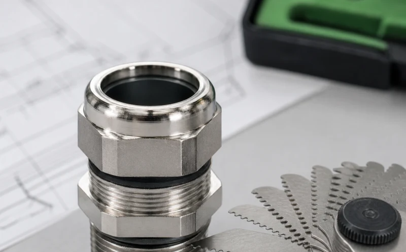
# 「M20 電纜密封接頭」究竟代表什麼？規格拆解

> Source: https://chinacableglands.com/zh-hant/blog/what-does-m20-cable-gland-actually-mean-a-spec-breakdown/
> Language: zh-Hant
> Publisher: 倍拓電纜接頭
> Author: Henry Xu
> Published: 2026-05-02
> Updated: 2026-10-29

解讀 M20 電纜密封接頭規格：20 mm 標稱引入口螺紋、螺距、可用螺紋長度、面板開孔及電纜範圍，並比較三個安裝選型實例。

<p>「<strong>M20 電纜密封接頭</strong>」採用公制外殼引入口螺紋，標稱直徑為 20 mm。完整標示 <strong>M20 × 1.5</strong> 另指出螺距為 1.5 mm。我會將外殼側配合與電纜範圍分開檢查：數字 20 表示引入口螺紋規格，並非 20 mm 的電纜開口。</p>
<p>選型時，應一併查看三組尺寸：旋入外殼的螺紋、穿過面板可用的長度，以及密封件可接受的電纜直徑。即使兩個接頭具有相同的 M20 引入口，其餘兩項尺寸仍可能不同。</p>
<blockquote>
<p><strong>重點摘要</strong></p>
<ul>
<li>M20 表示公制引入口螺紋的標稱直徑。</li>
<li>在圖面上標明數字螺距及介面標準；M20 × 1.5 已明確列出螺距。</li>
<li>依接頭型式的電纜密封範圍，配合已完成電纜的完整外徑區間。</li>
<li>將攻牙引入口與搭配鎖緊螺帽的間隙孔，視為不同的安裝方式進行檢查。</li>
<li>在可用外螺紋長度內，為面板、墊圈及所需旋合長度預留空間。</li>
</ul>
</blockquote>
<h2 id="decode-the-m20-cable-gland-designation">解讀 M20 電纜密封接頭標示</h2>
<p><strong>標稱直徑</strong>是用來命名螺紋規格的尺寸。M20 中的 20 表示 20 mm。<strong>螺距</strong>是相鄰螺紋上對應點之間、沿軸向的間距。M20 × 1.5 中的 1.5 表示螺距為 1.5 mm；它不是壁厚、電纜尺寸或鎖緊預留量。</p>
<p><a href="https://webstore.iec.ch/en/publication/7034">IEC 62444:2010 範圍</a>涵蓋配有 IEC 60423 公制引入口螺紋的完整電纜密封接頭。<a href="https://webstore.iec.ch/en/publication/2112">IEC 60423:2007</a> 涵蓋導管與配件的螺紋尺寸。我會一併記錄完整的 M20 × 1.5 引入口標示及其介面標準，讓接收孔、鎖緊螺帽與接頭採用同一套規格。</p>
<table>
<thead>
<tr>
<th>標示或尺寸</th>
<th>所描述的項目</th>
<th>用途</th>
</tr>
</thead>
<tbody>
<tr>
<td>M20</td>
<td>公制引入口螺紋標稱直徑，20 mm</td>
<td>辨識外殼側的尺寸系列。</td>
</tr>
<tr>
<td>× 1.5</td>
<td>螺距，1.5 mm</td>
<td>配合對接螺紋，並計算理想軸向移動量。</td>
</tr>
<tr>
<td>可用外螺紋長度</td>
<td>從定義的安裝基準面起算，可用螺紋沿軸向的範圍</td>
<td>檢查壁厚與配件疊層。</td>
</tr>
<tr>
<td>電纜範圍</td>
<td>該型式可接受的成品電纜外徑</td>
<td>依預定密封位置確認電纜是否適用。</td>
</tr>
<tr>
<td>扳手尺寸</td>
<td>指定扳手平面之間的寬度</td>
<td>規劃工具操作空間及各引入口之間的間距。</td>
</tr>
</tbody>
</table>
<p>這就是我在替換訂單上保留完整標示的原因。在已定義的圖面系統內，「M20」可作為簡稱；但團隊或供應商更換時，螺距與介面細節也必須隨零件一併傳遞。《<a href="/zh-hant/blog/pg-vs-metric-vs-npt-threads-which-cable-gland-threading-system-should-you-choose/">公制、PG 與 NPT 螺紋指南</a>》說明各螺紋系列的差異。</p>
<p>《<a href="https://assets.publishing.service.gov.uk/media/5a7ed602e5274a2e8ab48826/November_Bulletin.pdf">英國 AAIB 調查報告，印刷頁第 163 頁</a>》提供了油濾器安裝的實例。報告區分 M20 × 1.5 與 3/4 × 16 螺紋：兩者螺距相近，但直徑不同。即使配錯螺紋的濾器仍可鎖緊，其旋合量也較少。對電纜引入口而言，同樣的配合經驗也適用：只能部分旋入或感覺已鎖緊，都不能取代完整核對螺紋規格。</p>
<h2 id="why-a-caliper-reading-is-only-part-of-thread-inspection">為什麼卡尺讀值只涵蓋螺紋檢查的一部分</h2>
<p><strong>大徑</strong>是沿外螺紋牙頂量得的直徑。成品 M20 螺紋的實測值可能低於標稱 20 mm，因為實際尺寸由適用的螺紋限值界定。應將量測尺寸與圖面限值比較，不要把 20.000 mm 當成通用驗收值。</p>
<p><strong>螺紋節徑</strong>是穿過螺紋牙形的中間基準圓柱直徑，會影響牙側之間的配合。<a href="https://www.nist.gov/publications/pitch-diameter-measurement-threaded-gages-using-cmm">NIST 螺紋量規量測研究</a>指出，螺紋節徑圓柱是量測基準，並討論其量測不確定度。因此，量測牙頂直徑或使用螺距規檢查，都只能回答部分檢查問題。</p>
<p>我會先用螺距規辨識可能的螺距，再依介面檢查所需尺寸及量規。外螺紋與內螺紋的配合限值、塗層狀態及可用長度，應納入同一次圖面審查。若零件旋入不久便卡住，或在引入口內晃動，應先檢查配合螺紋，再使用扳手。</p>
<img alt="公制螺距規置於金屬電纜引入零件旁。" src="/images/blog/what-does-m20-cable-gland-actually-mean-a-spec-breakdown/m20-thread-pitch-gauge-inspection.webp" width="800" height="498" loading="lazy" decoding="async">
<p><em>一組螺距規葉片放在金屬引入零件旁。將其中一片與螺紋配合，有助於辨識螺距；完整配合檢查仍由圖面及指定量規界定。</em></p>
<h3 id="worked-example-pitch-and-free-axial-travel">實例：螺距與自由軸向移動量</h3>
<p>對單線螺紋而言，旋轉一整圈的理想軸向前進量等於螺距。假設兩個相配的 M20 × 1.5 零件在接觸前有 3.75 mm 的自由軸向移動量，理想旋轉圈數為：</p>
<div class="article-math article-math-display" data-latex="N=\frac{A}{P}=\frac{3.75}{1.5}=2.5\ \text{turns}"><span class="katex"><math xmlns="http://www.w3.org/1998/Math/MathML" display="block"><semantics><mrow><mi>N</mi><mo>=</mo><mfrac><mi>A</mi><mi>P</mi></mfrac><mo>=</mo><mfrac><mn>3.75</mn><mn>1.5</mn></mfrac><mo>=</mo><mn>2.5</mn><mtext> turns</mtext></mrow><annotation encoding="application/x-tex">N=\frac{A}{P}=\frac{3.75}{1.5}=2.5\ \text{turns}</annotation></semantics></math></span></div>
<p>此處，<span class="article-math article-math-inline" data-latex="A"><span class="katex"><math xmlns="http://www.w3.org/1998/Math/MathML"><semantics><mrow><mi>A</mi></mrow><annotation encoding="application/x-tex">A</annotation></semantics></math></span></span> 表示假設的自由軸向移動量（單位為毫米），<span class="article-math article-math-inline" data-latex="P"><span class="katex"><math xmlns="http://www.w3.org/1998/Math/MathML"><semantics><mrow><mi>P</mi></mrow><annotation encoding="application/x-tex">P</annotation></semantics></math></span></span> 表示每圈以毫米表示的螺距。旋轉兩圈半相當於 900°。這是螺紋相配且可自由轉動時的幾何示例。密封件或肩部一旦接觸，應依產品的鎖緊說明操作；移動量計算不會決定最終壓縮量。</p>
<p><a class="article-tool-card article-tool-card-link" href="/zh-hant/resource-center/tools/metric-thread-pitch-turns-calculator/" aria-label="公制螺紋螺距與圈數計算器"><span class="article-tool-card-index">工具</span><span class="article-tool-card-kicker">螺紋與引入口幾何尺寸</span><strong class="article-tool-card-title">公制螺紋螺距與圈數計算器</strong><span class="article-tool-card-copy">輸入接頭圖面上的螺距與自由軸向移動距離，以比較理想旋轉圈數。將實際承靠面、螺紋退尾段及可用螺紋嚙合納入考量，最後依產品規定的鎖緊方式操作。</span><span class="article-tool-card-formula">N = L / P; θ = 360° × N</span><span class="article-tool-card-inputs" aria-label="計算器輸入項目"><em>螺距</em><em>所需軸向移動距離</em></span><span class="article-tool-card-action">開啟計算器 <span aria-hidden="true">-&gt;</span></span></a></p><p>《<a href="/zh-hant/blog/m20x1-5-vs-m20-the-engineers-guide-to-fine-pitch-gland-threads/">M20 與 M20 × 1.5 比較指南</a>》更詳細說明螺距識別及螺紋不匹配問題。在本規格拆解中，我用螺距計算了解移動量，並將它與強度及密封檢查分開。</p>
<h2 id="allow-for-usable-thread-and-the-panel-stack">預留可用螺紋及面板疊層所需空間</h2>
<p><strong>可用螺紋</strong>是供預定對接旋合使用的完整牙形部分。倒角與螺紋退尾段含有不完整牙形，因此從肩部到端部的可見距離，可能高估鎖緊螺帽或攻牙凸台實際可用的螺紋長度。計算疊層前，先在圖面上標出安裝基準及完整牙形螺紋的界限。</p>
<p>在間隙孔安裝中，接頭安裝基準與鎖緊螺帽之間的面板及任何墊圈都會占用軸向空間。剩餘的完整牙形螺紋必須符合規定的鎖緊螺帽旋合長度。若使用攻牙引入口，也要檢查內螺紋深度、肩部間隙及盲孔底部。</p>
<p>我會在本體獲得支撐且工具與螺紋軸線對齊時，從圖面基準面量至螺紋末端，以量測軸向伸出量。我會分別記錄螺紋退尾段及末端倒角。即使可見螺紋很長，加入厚壁面或凹入式引入口後，完整牙形螺紋仍可能不足。</p>
<figure>
<picture>
<source media="(max-width: 640px)" srcset="/images/blog/what-does-m20-cable-gland-actually-mean-a-spec-breakdown/m20-entry-thread-axial-projection-600.webp">
<img alt="數位卡尺對準電纜密封接頭的引入螺紋，一個量測面位於肩部基準，另一個位於螺紋末端。" src="/images/blog/what-does-m20-cable-gland-actually-mean-a-spec-breakdown/m20-entry-thread-axial-projection.webp" width="1200" height="750" loading="lazy" decoding="async">
</picture>
<figcaption>卡尺跨在肩部區域與螺紋末端之間，接頭放在支撐塊上。記錄軸向伸出量時，應使用圖面定義的基準面。</figcaption>
</figure>
<h3 id="worked-example-the-same-thread-size-different-mounting-fit">實例：相同螺紋尺寸，不同的安裝配合</h3>
<p>假設面板厚 5.0 mm，指定的端面墊圈在安裝狀態下占用 1.0 mm。此假設組件需要 4.0 mm 的完整牙形螺紋供鎖緊螺帽旋合。所需的最小可用長度為：</p>
<div class="article-math article-math-display" data-latex="L_{\mathrm{required}}=5.0+1.0+4.0=10.0\ \mathrm{mm}"><span class="katex"><math xmlns="http://www.w3.org/1998/Math/MathML" display="block"><semantics><mrow><msub><mi>L</mi><mrow><mi mathvariant="normal">r</mi><mi mathvariant="normal">e</mi><mi mathvariant="normal">q</mi><mi mathvariant="normal">u</mi><mi mathvariant="normal">i</mi><mi mathvariant="normal">r</mi><mi mathvariant="normal">e</mi><mi mathvariant="normal">d</mi></mrow></msub><mo>=</mo><mn>5.0</mn><mo>+</mo><mn>1.0</mn><mo>+</mo><mn>4.0</mn><mo>=</mo><mn>10.0</mn><mtext> </mtext><mrow><mi mathvariant="normal">m</mi><mi mathvariant="normal">m</mi></mrow></mrow><annotation encoding="application/x-tex">L_{\mathrm{required}}=5.0+1.0+4.0=10.0\ \mathrm{mm}</annotation></semantics></math></span></div>
<p>在這個簡化示例中，列出的可用長度已將倒角與螺紋退尾段納入考量，且鎖緊螺帽所需區段具有完整牙形螺紋。可用長度為 9.5 mm 時，扣除面板與墊圈後剩下 3.5 mm，比假設要求少 0.5 mm。可用長度為 12.0 mm 時，剩下 6.0 mm，比該要求多 2.0 mm。</p>
<p>兩個零件都可能採用 M20 × 1.5。若其餘配合及性能檢查都通過，較長的可用螺紋長度即可解決所述疊層問題，沒有必要更改螺紋標稱直徑。實際接頭與配件圖面才是旋合要求的依據；4.0 mm 是本示例的輸入值，不是通用的 M20 規則。</p>
<h2 id="choose-the-receiving-entry-geometry">選擇接收端引入口幾何</h2>
<p><strong>攻牙引入口</strong>具有與接頭配合的內螺紋。先核對螺紋系列、標稱直徑、螺距及配合，再檢查可用深度與導入端。盲孔引入口應保留規定的端部間隙，讓接頭先到達密封座面，再抵到底部。檢查肩部的密封承面，並使用指定的端面密封或螺紋密封。</p>
<p><strong>間隙孔</strong>是未加工螺紋的開口，供接頭外螺紋穿過。鎖緊螺帽從另一側固定接頭。孔徑與公差必須允許外螺紋通過，同時保留規定的密封承面及配件支撐。這些尺寸應依接頭與外殼圖面確認。僅有 20 mm 標稱螺紋規格，並不足以作為開孔指示。</p>
<p><strong>轉接頭或縮徑接頭</strong>可連接兩個已定義的介面。記錄兩側的螺紋、螺距及外螺紋或內螺紋形式，再將其增加的長度納入疊層。也要檢查新增的密封面及工具操作空間。《<a href="/zh-hant/blog/how-to-select-the-correct-entry-hole-size-for-your-cable-gland/">引入口孔徑選型指南</a>》說明接收開口的相關細節。</p>
<p>對於間隙孔引入口，我會依預定順序試裝本體、端面墊圈、面板及鎖緊螺帽。配合檢查時先不要鎖緊螺帽，並另外支撐電纜。最終鎖緊前，檢查兩側是否有扳手操作空間、附近是否受阻，以及可用螺紋長度是否足夠。</p>
<figure>
<picture>
<source media="(max-width: 640px)" srcset="/images/blog/what-does-m20-cable-gland-actually-mean-a-spec-breakdown/m20-clearance-hole-stack-dry-fit-600.webp">
<img alt="電纜密封接頭穿過垂直面板進行乾式試裝，墊圈位於外側，尚未鎖緊的鎖緊螺帽位於內側螺紋上，電纜由獨立支撐承托。" src="/images/blog/what-does-m20-cable-gland-actually-mean-a-spec-breakdown/m20-clearance-hole-stack-dry-fit.webp" width="1200" height="750" loading="lazy" decoding="async">
</picture>
<figcaption>乾式試裝時，墊圈置於面板外側，尚未鎖緊的鎖緊螺帽位於內側。另一個獨立支撐承托電纜，以便檢查各層的疊合情況。</figcaption>
</figure>
<figure class="blog-chart" style="container-type: inline-size;">
<svg xmlns="http://www.w3.org/2000/svg" viewBox="0 0 520 1280" role="img" aria-labelledby="cg-m20-boundary-title cg-m20-boundary-desc" style="display:block;max-width:520px;margin-inline:auto;font-family:var(--font-body); width: 100% !important; max-width: 100% !important; height: auto !important;" id="cg-typography-153557a262310fcc">
<style>
#cg-typography-153557a262310fcc { --svg-body-screen: 17px; }
@media (max-width: 760px) { #cg-typography-153557a262310fcc { --svg-body-screen: 16px; } }
</style>
<title id="cg-m20-boundary-title">M20 電纜密封接頭引入口的尺寸檢查項目</title>
<desc id="cg-m20-boundary-desc">三個堆疊圖分別呈現電纜外徑與密封件接觸、M20 × 1.5 入口螺紋、外殼壁與配件疊層，以及剩餘可用外螺紋長度。</desc>
<text x="260" y="42" text-anchor="middle" fill="var(--color-carbon)" font-size="28" font-weight="700" style="font-size: calc(22px * 520px / 100cqw) !important;">M20 標示入口螺紋</text>
<text x="260" y="78" text-anchor="middle" fill="var(--color-carbon)" font-size="28" font-weight="700" style="font-size: calc(22px * 520px / 100cqw) !important;">電纜配合須另行檢查</text>
<text x="260" y="120" text-anchor="middle" fill="var(--color-graphite)" font-size="19" style="font-size: calc(var(--svg-body-screen) * 520px / 100cqw) !important;">面板疊層包括接頭、壁面、</text>
<text x="260" y="149" text-anchor="middle" fill="var(--color-graphite)" font-size="19" style="font-size: calc(var(--svg-body-screen) * 520px / 100cqw) !important;">墊圈、鎖緊螺帽及可用螺紋。</text>
<rect x="28" y="180" width="464" height="280" rx="18" fill="var(--surface-card)" stroke="var(--color-pewter)" stroke-width="3"/>
<text x="52" y="222" fill="var(--color-carbon)" font-size="22" font-weight="700" style="font-size: calc(18px * 520px / 100cqw) !important;">1. 電纜＋密封件</text>
<text x="52" y="260" fill="var(--color-graphite)" font-size="19" style="font-size: calc(var(--svg-body-screen) * 520px / 100cqw) !important;">使電纜 OD 符合密封範圍。</text>
<text x="52" y="289" fill="var(--color-graphite)" font-size="19" style="font-size: calc(var(--svg-body-screen) * 520px / 100cqw) !important;">在指定的電纜層上形成密封。</text>
<rect x="190" y="316" width="140" height="72" rx="18" fill="var(--color-ash)" stroke="var(--color-graphite)" stroke-width="3"/>
<rect x="190" y="339" width="140" height="26" fill="var(--surface-card)"/>
<rect x="218" y="330" width="84" height="11" rx="3" fill="var(--color-primary)"/>
<rect x="218" y="363" width="84" height="11" rx="3" fill="var(--color-primary)"/>
<path d="M82 352H438" stroke="var(--color-graphite)" stroke-width="22" stroke-linecap="round"/>
<path d="M82 352H438" stroke="var(--surface-card)" stroke-width="14" stroke-linecap="round"/>
<text x="260" y="432" text-anchor="middle" fill="var(--color-graphite)" font-size="19" style="font-size: calc(16px * 520px / 100cqw) !important;">電纜外徑 · 密封接觸 · 接頭本體</text>
<rect x="28" y="490" width="464" height="350" rx="18" fill="var(--surface-card)" stroke="var(--color-primary)" stroke-width="3"/>
<text x="52" y="532" fill="var(--color-carbon)" font-size="22" font-weight="700" style="font-size: calc(18px * 520px / 100cqw) !important;">2. M20 × 1.5 引入口</text>
<text x="52" y="570" fill="var(--color-graphite)" font-size="19" style="font-size: calc(var(--svg-body-screen) * 520px / 100cqw) !important;">標示完整的螺紋規格。</text>
<text x="52" y="599" fill="var(--color-graphite)" font-size="19" style="font-size: calc(var(--svg-body-screen) * 520px / 100cqw) !important;">核對配合及可用外螺紋長度。</text>
<path d="M120 642H308V666H278V734H308V758H120L92 738V662Z" fill="var(--color-ash)" stroke="var(--color-graphite)" stroke-width="3"/>
<rect x="92" y="686" width="190" height="28" fill="var(--surface-card)"/>
<rect x="118" y="674" width="30" height="16" fill="var(--color-primary)"/>
<rect x="118" y="710" width="30" height="16" fill="var(--color-primary)"/>
<path d="M278 666H430V686H278M278 714H430V734H278" fill="var(--color-ash)" stroke="var(--color-graphite)" stroke-width="3"/>
<rect x="308" y="638" width="14" height="28" fill="var(--color-primary)"/>
<rect x="308" y="734" width="14" height="28" fill="var(--color-primary)"/>
<rect x="322" y="620" width="24" height="46" fill="var(--color-graphite)"/>
<rect x="322" y="734" width="24" height="46" fill="var(--color-graphite)"/>
<path d="M346 646H390L410 666H346ZM346 734H410L390 754H346Z" fill="var(--color-ash)" stroke="var(--color-graphite)" stroke-width="3"/>
<path d="M282 666l8 8M282 734l8 -8" stroke="var(--color-primary)" stroke-width="3"/>
<path d="M298 666l8 8M298 734l8 -8" stroke="var(--color-primary)" stroke-width="3"/>
<path d="M314 666l8 8M314 734l8 -8" stroke="var(--color-primary)" stroke-width="3"/>
<path d="M330 666l8 8M330 734l8 -8" stroke="var(--color-primary)" stroke-width="3"/>
<path d="M346 666l8 8M346 734l8 -8" stroke="var(--color-primary)" stroke-width="3"/>
<path d="M362 666l8 8M362 734l8 -8" stroke="var(--color-primary)" stroke-width="3"/>
<path d="M378 666l8 8M378 734l8 -8" stroke="var(--color-primary)" stroke-width="3"/>
<path d="M394 666l8 8M394 734l8 -8" stroke="var(--color-primary)" stroke-width="3"/>
<path d="M410 666l8 8M410 734l8 -8" stroke="var(--color-primary)" stroke-width="3"/>
<path d="M70 700H450" stroke="var(--color-graphite)" stroke-width="20" stroke-linecap="round"/>
<path d="M70 700H450" stroke="var(--surface-card)" stroke-width="12" stroke-linecap="round"/>
<text x="260" y="798" text-anchor="middle" fill="var(--color-graphite)" font-size="19" style="font-size: calc(16px * 520px / 100cqw) !important;">本體 · M20 × 1.5 螺紋 · 墊圈</text>
<text x="260" y="825" text-anchor="middle" fill="var(--color-graphite)" font-size="19" style="font-size: calc(16px * 520px / 100cqw) !important;">壁面 · 鎖緊螺帽</text>
<rect x="28" y="870" width="464" height="250" rx="18" fill="var(--surface-card)" stroke="var(--color-pewter)" stroke-width="3"/>
<text x="52" y="912" fill="var(--color-carbon)" font-size="22" font-weight="700" style="font-size: calc(18px * 520px / 100cqw) !important;">3. 可用螺紋長度</text>
<text x="52" y="950" fill="var(--color-graphite)" font-size="19" style="font-size: calc(var(--svg-body-screen) * 520px / 100cqw) !important;">將面板及墊圈計入</text>
<text x="52" y="979" fill="var(--color-graphite)" font-size="19" style="font-size: calc(var(--svg-body-screen) * 520px / 100cqw) !important;">可用外螺紋長度。</text>
<line x1="92" y1="1028" x2="428" y2="1028" stroke="var(--color-primary)" stroke-width="4"/>
<line x1="92" y1="1014" x2="92" y2="1042" stroke="var(--color-primary)" stroke-width="4"/>
<line x1="428" y1="1014" x2="428" y2="1042" stroke="var(--color-primary)" stroke-width="4"/>
<text x="260" y="1071" text-anchor="middle" fill="var(--color-graphite)" font-size="19" style="font-size: calc(var(--svg-body-screen) * 520px / 100cqw) !important;">剩餘的完整牙形螺紋</text>
<text x="260" y="1098" text-anchor="middle" fill="var(--color-graphite)" font-size="19" style="font-size: calc(var(--svg-body-screen) * 520px / 100cqw) !important;">供鎖緊螺帽達到規定旋合長度</text>
<rect x="28" y="1150" width="464" height="100" rx="16" fill="var(--color-ash)" stroke="var(--color-pewter)" stroke-width="3"/>
<text x="260" y="1191" text-anchor="middle" fill="var(--color-carbon)" font-size="20" font-weight="700" style="font-size: calc(18px * 520px / 100cqw) !important;">將電纜配合與入口配合</text>
<text x="260" y="1222" text-anchor="middle" fill="var(--color-carbon)" font-size="20" font-weight="700" style="font-size: calc(18px * 520px / 100cqw) !important;">分成兩項各自獨立的通過／不通過檢查</text>
</svg>
<figcaption>電纜與密封件的配合，以及接頭與外殼引入口的配合，需要分開檢查。圖中端面密封墊圈位於壁面外側；鎖緊螺帽則在內側與可用螺紋旋合。</figcaption>
</figure>
<h2 id="match-the-cable-range-to-the-chosen-m20-variant">依所選 M20 型式配合電纜範圍</h2>
<p><strong>電纜密封範圍</strong>是特定接頭型式及組件可接受的成品電纜外徑區間。先確認電纜外徑的最小值與最大值，並納入製造公差。該區間兩端都必須落在接頭聲明的範圍內。</p>
<p>接著，我會檢查密封件下方的表面。設計可能要求連續且圓形的外被；肋紋、橢圓度、鎧裝、編織層或外被轉接處，都會改變接觸狀況。對於帶屏蔽或鎧裝的構造，請依剖面圖比較每個額外接觸點、夾具及密封直徑。《<a href="/zh-hant/blog/double-compression-vs-single-compression-glands-a-definitive-guide/">單壓縮與雙壓縮接頭指南</a>》說明這些不同介面。</p>
<p>接續使用面板假設範例，電纜 OD 為 10.0–10.6 mm。假設下列三個候選型式都具有正確的 M20 × 1.5 介面，並使用相同的指定端面墊圈，其安裝後厚度為 1.0 mm；三者的圓形外被構造也都相容。5.0 mm 面板及 4.0 mm 旋合要求保持不變。</p>
<table>
<thead>
<tr>
<th>假設的 M20 型式</th>
<th>電纜範圍</th>
<th>可用外螺紋長度</th>
<th>10.0–10.6 mm 電纜的配合情況</th>
<th>面板與墊圈 6.0 mm 疊層後剩餘的完整螺紋</th>
<th>尺寸判定</th>
</tr>
</thead>
<tbody>
<tr>
<td>A</td>
<td>6.0–12.0 mm</td>
<td>9.5 mm</td>
<td>在範圍內</td>
<td>3.5 mm；比要求少 0.5 mm</td>
<td>選擇較長的可用螺紋長度。</td>
</tr>
<tr>
<td>B</td>
<td>10.5–14.0 mm</td>
<td>12.0 mm</td>
<td>電纜外徑的 10.0 mm 下限低於該型式範圍下限</td>
<td>6.0 mm；符合假設的 4.0 mm 要求</td>
<td>選用電纜範圍合適的型式。</td>
</tr>
<tr>
<td>C</td>
<td>6.0–12.0 mm</td>
<td>12.0 mm</td>
<td>在範圍內</td>
<td>6.0 mm；符合假設的 4.0 mm 要求</td>
<td>兩項尺寸檢查皆符合。</td>
</tr>
</tbody>
</table>
<p>在這個假設比較中，我發現只有 C 同時符合電纜和安裝疊層要求。A 符合電纜範圍，但螺紋太短；B 可穿過面板，卻未涵蓋部分電纜公差範圍。若只根據共同的 M20 標示選型，這兩種失效情況都會被掩蓋。</p>
<p>我會將 C 納入後續應用檢查：本體與密封件材料、外被相容性、保持力、環境及所需安裝方法。此表只提供尺寸選型；產品聲明的性能仍須符合該工況。</p>
<h2 id="turn-the-designation-into-a-complete-specification">將標示轉化為完整規格</h2>
<p>實用的 M20 規格應將引入口細節與確切接頭型式及其預定電纜配對。下列欄位讓外殼設計者、安裝人員與採購人員依據相同組件作業：</p>
<ol>
<li>完整接頭料號及現行圖面版次。</li>
<li>M20 × 1.5 引入口標示、介面標準及適用的配合限值。</li>
<li>可用外螺紋長度及所需旋合長度，並標明基準面。</li>
<li>攻牙引入口細節，或間隙孔直徑及公差。</li>
<li>面板厚度、密封承面、墊圈、鎖緊螺帽及任何轉接頭或接地片。</li>
<li>電纜標示、完整 OD 區間、外被形狀，以及各額外鎧裝或屏蔽介面。</li>
<li>本體與密封件材料、所需性能、鎖緊方法及操作空間。</li>
</ol>
<p><strong>侵入防護</strong>描述 IP 代碼所分類的外殼防護程度。《<a href="https://webstore.iec.ch/en/publication/2452">IEC 60529 範圍</a>》涉及此外殼分類。對接頭引入口而言，應選用指定的電纜與配件、準備密封承面，並遵循與所需防護程度相關的組裝條件。</p>
<p>我會將材料、溫度、腐蝕、保持力、EMC 及危險區域要求，與尺寸一併視為應用選型條件。M20 引入口也可用於為截然不同工況設計的產品。請查閱所選構造的相關產品資料及核准條件，再確認安裝空間足以容納本體、扳手及電纜彎曲。</p>
<p>若文件對引入口螺紋、密封範圍、夾持範圍或鎖緊螺帽的用語不一致，可查閱<a href="/zh-hant/resource-center/cable-entry-glossary/">電纜引入口術語表</a>。若曝露情況包含洪水或積水，<a href="/zh-hant/blog/the-engineers-guide-to-deluge-proof-glands-for-extreme-weather-protection/">極端天候引入口指南</a>會說明這項不同的工況評估。</p>
<h2 id="conclusion">結論</h2>
<p>M20 告訴我公制外殼引入口螺紋的標稱尺寸。我會將螺距及介面標準與該標示一併記錄，再檢查穿過面板所需的可用長度，以及確切接頭型式的電纜範圍。</p>
<p>這項範例比較說明為何兩類檢查必須分開：接頭可能適合電纜，螺紋卻仍太短；也可能適合面板，卻不符合電纜的最小直徑。選用同時符合兩項要求的型式，再確認其材料、性能及安裝條件適用於該應用。</p>
<h2 id="faqs-about-m20-cable-gland-specifications">M20 電纜密封接頭規格常見問題</h2>
<h3 id="why-can-an-m20-male-thread-measure-slightly-under-20-mm">為什麼 M20 外螺紋的實測直徑可能略小於 20 mm？</h3>
<p>M20 是標稱尺寸。適用的螺紋尺寸及公差界定成品外徑。應依據這些限值比較量測結果並進行指定配合檢查；卡尺量測牙頂不能檢查完整螺紋牙形。</p>
<h3 id="can-i-install-an-m20-gland-in-a-20-mm-punched-hole">我可以將 M20 接頭裝入 20 mm 沖孔嗎？</h3>
<p>請使用所選接頭及安裝方式指定的間隙孔直徑與公差。開口必須讓外螺紋通過，同時支撐所需墊圈與密封承面。面板厚度、孔口表面處理及鎖緊螺帽的操作空間也會影響配合。</p>
<h3 id="is-an-m20--15-gland-interchangeable-with-any-part-marked-m20">標示為 M20 的零件都能與 M20 × 1.5 接頭互換嗎？</h3>
<p>先核對完整螺紋系統、螺距及配合，再比較可用長度、外螺紋／內螺紋形式、密封座面及配件疊層。僅有相同標稱直徑或部分手動旋入，仍無法確定其他尺寸是否相符。</p>
<h3 id="which-cable-diameter-fits-an-m20-gland">哪種電纜直徑適用於 M20 接頭？</h3>
<p>請使用確切接頭型式的電纜範圍。成品電纜外徑的最小值與最大值都必須落在該範圍內，且外被形狀及密封位置須符合設計。不同 M20 型式可接受不同的電纜範圍。</p>
<h3 id="sources-and-technical-references">來源與技術參考資料</h3>
<ul>
<li><a href="https://webstore.iec.ch/en/publication/2112">IEC 60423:2007 — 導管及配件螺紋尺寸</a>，查閱日期：2026-10-29。</li>
<li><a href="https://webstore.iec.ch/en/publication/7034">IEC 62444:2010 — 電氣裝置用電纜密封接頭</a>，查閱日期：2026-10-29。</li>
<li><a href="https://webstore.iec.ch/en/publication/2452">IEC 60529 — 外殼提供的防護等級（IP 代碼）</a>，查閱日期：2026-10-29。</li>
<li><a href="https://assets.publishing.service.gov.uk/media/5a7ed602e5274a2e8ab48826/November_Bulletin.pdf">英國 AAIB 公報 11/2006 — G-CCKF 油濾器比較（印刷頁第 163 頁）</a>，查閱日期：2026-10-29。</li>
<li><a href="https://www.nist.gov/publications/pitch-diameter-measurement-threaded-gages-using-cmm">NIST — 使用 CMM 量測螺紋量規節徑</a>，查閱日期：2026-10-29。</li>
</ul>