# 電纜密封接頭尺寸選型完整指南：如何讓接頭與電纜外徑相配

> Source: https://chinacableglands.com/zh-hant/blog/the-ultimate-guide-to-cable-gland-sizing-how-to-match-glands-to-cable-diameters/
> Language: zh-Hant
> Publisher: 倍拓電纜接頭
> Author: Leo Xu
> Published: 2026-04-18
> Updated: 2026-10-22

先將電纜完整外徑區間與接頭密封範圍比較，再確認鎧裝、入口螺紋、外殼壁面及安裝配合。

<p><strong>電纜密封接頭尺寸選型</strong>會將電纜完整外徑（OD）區間，對照所選接頭與密封件面向電纜的範圍。我會先確認這項配合，再檢查電纜結構、入口螺紋或開口、壁厚、配件、環境及說明。M20 表示入口螺紋；它不代表電纜範圍。</p>
<p>我會在預定密封位置測量成品電纜，並保留其生產規格的最小與最大限值。將兩者與接頭範圍比較。使用<a href="/zh-hant/blog/how-do-you-decode-cable-gland-size-charts-to-match-your-cable-diameter-perfectly/">尺寸表</a>之前，先確認製造商、系列、版次及單位，確保選定列項仍對應該接頭。</p>
<blockquote>
<p><strong>重點整理</strong></p>
<ul>
<li>記錄成品電纜的最小與最大外徑（OD）；註明量帶讀取的是圓周長還是直徑。</li>
<li>將完整電纜尺寸區間與確切接頭所聲明的密封或夾持區間比較。</li>
<li>將外護套、內墊層、鎧裝及屏蔽接觸尺寸分別記錄。</li>
<li>將電纜端配合與外殼引入口配合視為兩項獨立檢查。</li>
<li>依產品圖面與安裝說明確認最終型號及鎖緊方式。</li>
</ul>
</blockquote>
<h2 id="start-with-the-three-dimensions-that-must-match">先確認必須相符的三個尺寸</h2>
<p><strong>適切的電纜密封接頭選型須使三個介面對齊：</strong>成品電纜在密封處、接頭必須夾持或接觸的其他電纜層，以及接頭與外殼之間的安裝介面。每個介面都有各自的尺寸；一項通過，不能補償另一項不匹配。</p>
<p><a href="https://webstore.iec.ch/en/publication/7034">IEC 62444:2010</a>對供應狀態下完整電纜密封接頭的結構與性能規定要求及試驗。其涵蓋採用 IEC 60423 公制引入螺紋的接頭，也可在其明定範圍內適用於其他引入螺紋類型。因此，尺寸標示屬於完整產品配置的一部分，並非通用的電纜範圍。</p>
<figure class="blog-chart" style="container-type: inline-size;">
<svg xmlns="http://www.w3.org/2000/svg" viewBox="0 0 480 955" role="img" aria-labelledby="cgsz-title cgsz-desc" style="font-family:var(--font-body); width: 100% !important; max-width: 100% !important; height: auto !important;" id="cg-typography-56e8fcbb1d56e6f8">
<style>
#cg-typography-56e8fcbb1d56e6f8 { --svg-body-screen: 17px; }
@media (max-width: 760px) { #cg-typography-56e8fcbb1d56e6f8 { --svg-body-screen: 16px; } }
</style>
<title id="cgsz-title">電纜密封接頭尺寸選型的三個介面</title>
<desc id="cgsz-desc">垂直尺寸選型圖從成品電纜直徑區間，依序連到接頭面向電纜的範圍，再到外殼引入口與壁面堆疊配置。</desc>
<defs><marker id="cgsz-arrow" markerWidth="8" markerHeight="8" refX="7" refY="4" orient="auto"><path d="M0 0L8 4L0 8Z" fill="var(--color-primary)"/></marker></defs>
<text x="240" y="42" text-anchor="middle" fill="var(--color-carbon)" font-size="25" font-weight="700" style="font-size: calc(22px * 480px / 100cqw) !important;">核對三個介面尺寸</text>
<rect x="24" y="76" width="432" height="216" rx="18" fill="var(--surface-card)" stroke="var(--color-primary)" stroke-width="3"/>
<text x="48" y="118" fill="var(--color-primary)" font-size="20" font-weight="700" style="font-size: calc(18px * 480px / 100cqw) !important;">1. 密封處的成品電纜</text>
<text x="48" y="158" fill="var(--color-carbon)" font-size="17" font-weight="700" style="font-size: calc(var(--svg-body-screen) * 480px / 100cqw) !important;">記錄完整外徑區間</text>
<text x="48" y="192" fill="var(--color-graphite)" font-size="16" style="font-size: calc(16px * 480px / 100cqw) !important;">最小外徑：Dmin</text>
<text x="48" y="224" fill="var(--color-graphite)" font-size="16" style="font-size: calc(16px * 480px / 100cqw) !important;">最大外徑：Dmax</text>
<text x="48" y="256" fill="var(--color-graphite)" font-size="16" style="font-size: calc(var(--svg-body-screen) * 480px / 100cqw) !important;">橢圓截面的長軸與短軸外徑</text>
<path d="M240 304 V350" fill="none" stroke="var(--color-primary)" stroke-width="4" marker-end="url(#cgsz-arrow)"/>
<rect x="24" y="370" width="432" height="238" rx="18" fill="var(--surface-card)" stroke="var(--color-primary)" stroke-width="3"/>
<text x="48" y="412" fill="var(--color-primary)" font-size="20" font-weight="700" style="font-size: calc(18px * 480px / 100cqw) !important;">2. 接頭面向電纜的範圍</text>
<text x="48" y="452" fill="var(--color-carbon)" font-size="17" font-weight="700" style="font-size: calc(var(--svg-body-screen) * 480px / 100cqw) !important;">比較各個實際作用的介面</text>
<text x="48" y="486" fill="var(--color-graphite)" font-size="16" style="font-size: calc(var(--svg-body-screen) * 480px / 100cqw) !important;">護套密封件：Gmin 至 Gmax</text>
<text x="48" y="518" fill="var(--color-graphite)" font-size="16" style="font-size: calc(var(--svg-body-screen) * 480px / 100cqw) !important;">適用時的鎧裝或內墊層範圍</text>
<text x="48" y="550" fill="var(--color-graphite)" font-size="16" style="font-size: calc(var(--svg-body-screen) * 480px / 100cqw) !important;">貫通孔與準備方式</text>
<text x="48" y="582" fill="var(--color-graphite)" font-size="16" style="font-size: calc(var(--svg-body-screen) * 480px / 100cqw) !important;">嵌件、密封件及接頭變型識別</text>
<path d="M240 620 V666" fill="none" stroke="var(--color-primary)" stroke-width="4" marker-end="url(#cgsz-arrow)"/>
<rect x="24" y="686" width="432" height="170" rx="18" fill="var(--surface-card)" stroke="var(--color-primary)" stroke-width="3"/>
<text x="48" y="728" fill="var(--color-primary)" font-size="20" font-weight="700" style="font-size: calc(18px * 480px / 100cqw) !important;">3. 外殼介面</text>
<text x="48" y="768" fill="var(--color-carbon)" font-size="17" font-weight="700" style="font-size: calc(var(--svg-body-screen) * 480px / 100cqw) !important;">配合安裝配置</text>
<text x="48" y="802" fill="var(--color-graphite)" font-size="16" style="font-size: calc(var(--svg-body-screen) * 480px / 100cqw) !important;">螺紋或開孔、壁面及承靠面</text>
<text x="48" y="834" fill="var(--color-graphite)" font-size="16" style="font-size: calc(var(--svg-body-screen) * 480px / 100cqw) !important;">密封件、墊圈、鎖緊螺帽及可用螺紋</text>
<rect x="24" y="878" width="432" height="65" rx="12" fill="var(--color-primary)"/>
<text x="240" y="904" text-anchor="middle" fill="#fff" font-size="16" font-weight="700" style="font-size: calc(var(--svg-body-screen) * 480px / 100cqw) !important;"><tspan x="240" dy="0">所有必要介面皆符合 </tspan><tspan x="240" dy="25">同一配置</tspan></text>
</svg>
<figcaption>此尺寸圖將電纜外徑區間、接頭面向電纜的各範圍，以及外殼安裝堆疊配置分成三項獨立檢查。</figcaption>
</figure>
<p>我會用圖示區分三個介面。接著，依所選接頭的剖面圖找出密封件、夾持部、鎧裝錐、屏蔽接觸處、入口密封件及鎖緊螺帽的位置。將每一項<a href="/zh-hant/blog/what-is-cable-gland-clamping-range-and-why-does-it-matter-for-your-installation/">夾持範圍</a>套用至其實際作用的電纜層。</p>
<h2 id="measure-the-cable-at-the-sealing-location">在密封位置測量電纜</h2>
<p><strong>電纜外徑（OD）</strong>是密封件所在位置成品表面兩側之間的尺寸，也就是被測量尺寸。選擇量具前先說明要測量的表面：導體、剝除後的層、面板開口與接頭螺紋各自代表不同尺寸。</p>
<table>
<thead>
<tr>
<th>尺寸</th>
<th>測量或規定位置</th>
<th>在尺寸比較中的用途</th>
</tr>
</thead>
<tbody>
<tr>
<td>成品電纜外徑</td>
<td>密封處外護套的外側尺寸</td>
<td>與聲明的外護套密封範圍比較</td>
</tr>
<tr>
<td>裸導體直徑</td>
<td>金屬導體兩側之間的尺寸</td>
<td>不能代表成品電纜外徑</td>
</tr>
<tr>
<td>面板孔直徑</td>
<td>外殼開口兩側之間的尺寸</td>
<td>檢查安裝介面與入口密封件</td>
</tr>
<tr>
<td>標稱螺紋尺寸</td>
<td>完整螺紋標示中的尺寸</td>
<td>辨識配合螺紋，而非電纜範圍</td>
</tr>
</tbody>
</table>
<p><a href="https://knowledge.bsigroup.com/products/geometrical-product-specifications-gps-dimensional-tolerancing-part-1-linear-sizes">ISO 14405-1:2025</a> 提供線性尺寸特性的規定方式，包括圓柱特性的尺寸。其公開適用範圍不會為尺寸特性指定功能配合。選擇電纜密封接頭時，圖面必須標明聲明範圍所代表的表面及尺寸定義。</p>
<p>進料檢查時，我會清潔電纜表面與量具接觸面，並讓樣品達到規定狀態。避免壓縮柔軟的外護套。在不同方向讀取數值，並在印字、凸肋、過渡段、接續處、損傷或橢圓度可能影響尺寸時，沿密封區重複測量。保留最大與最小讀值，不要用平均值掩蓋局部限值。</p>
<h3 id="choose-between-a-caliper-circumference-tape-and-diameter-tape">選擇卡尺、圓周長量帶或直徑量帶</h3>
<p><strong>刻度決定量帶讀值的意義。</strong>卡尺讀取外護套兩側之間的距離；一般圓周長量帶讀取繞外護套一圈的距離；直徑量帶則以纏繞刻度直接顯示直徑。將數值輸入計算器前，先確認刻度標籤、單位、量程與使用說明。</p>
<table>
<thead>
<tr>
<th>量具</th>
<th>讀取的量</th>
<th>下一步</th>
</tr>
</thead>
<tbody>
<tr>
<td>外測爪卡尺</td>
<td>電纜局部橫向尺寸</td>
<td>按方向與位置重複測量，保留極值</td>
</tr>
<tr>
<td>一般圓周長量帶</td>
<td>圓周長，<span class="article-math article-math-inline" data-latex="C"><span class="katex"><math xmlns="http://www.w3.org/1998/Math/MathML"><semantics><mrow><mi>C</mi></mrow><annotation encoding="application/x-tex">C</annotation></semantics></math></span></span></td>
<td>以 <span class="article-math article-math-inline" data-latex="C/\pi"><span class="katex"><math xmlns="http://www.w3.org/1998/Math/MathML"><semantics><mrow><mi>C</mi><mi mathvariant="normal">/</mi><mi>π</mi></mrow><annotation encoding="application/x-tex">C/\pi</annotation></semantics></math></span></span> 換算一次，得到圓等效值</td>
</tr>
<tr>
<td>OD 直徑量帶，亦稱 π 量帶</td>
<td>由校正過的纏繞刻度顯示的直徑</td>
<td>記錄顯示的直徑；不要再除以 π</td>
</tr>
</tbody>
</table>
<p><a href="https://tsapps.nist.gov/publication/get_pdf.cfm?pub_id=917404">NIST 的 PI 量帶程序</a>說明會纏繞在圓形或圓柱形物件上並顯示其直徑的量帶，也討論了刻度內含的修正及量帶厚度造成的影響。請使用量具指定的 OD 刻度與方法，不要把任意繞在電纜上的帶條當成可互換的直徑量具。</p>
<p>使用卡尺時，應選擇適當的量爪與測力。<a href="https://www.npl.co.uk/resources/gpgs/callipers-micrometers">NPL 的卡尺指南</a>說明測力可能使柔軟材料變形，也說明對齊方式、溫度及量具狀態如何影響結果。加大壓力可能因外護套被壓扁而使顯示數值變小；這不會讓電纜外徑量得更準確。</p>
<p>環繞量帶應位於同一截面平面，不要沿電纜斜向繞行。遵循量具的張力與讀值說明，並確認該方法是否適用於外護套。實驗室校正量帶所用的力，不會自動成為適用於柔軟電纜的測力量。若兩種方法的結果不一致，先比較測量表面、方向與測力，再考慮平均讀值。</p>
<h3 id="convert-circumference-to-a-circular-equivalent-diameter">將圓周長換算為圓等效直徑</h3>
<p><strong>圓等效直徑</strong>是具有所測圓周長之圓的直徑。這是幾何換算，不是重新測量電纜長軸與短軸所得的尺寸。NIST 的 PI 量帶程序給出圓的關係式 <span class="article-math article-math-inline" data-latex="C=\pi D"><span class="katex"><math xmlns="http://www.w3.org/1998/Math/MathML"><semantics><mrow><mi>C</mi><mo>=</mo><mi>π</mi><mi>D</mi></mrow><annotation encoding="application/x-tex">C=\pi D</annotation></semantics></math></span></span>。重新整理後可得：</p>
<div class="article-math article-math-display" data-latex="D_{\mathrm{eq}}=\frac{C}{\pi}"><span class="katex"><math xmlns="http://www.w3.org/1998/Math/MathML" display="block"><semantics><mrow><msub><mi>D</mi><mrow><mi mathvariant="normal">e</mi><mi mathvariant="normal">q</mi></mrow></msub><mo>=</mo><mfrac><mi>C</mi><mi>π</mi></mfrac></mrow><annotation encoding="application/x-tex">D_{\mathrm{eq}}=\frac{C}{\pi}</annotation></semantics></math></span></div>
<p>其中，<span class="article-math article-math-inline" data-latex="C"><span class="katex"><math xmlns="http://www.w3.org/1998/Math/MathML"><semantics><mrow><mi>C</mi></mrow><annotation encoding="application/x-tex">C</annotation></semantics></math></span></span> 代表圓周長，<span class="article-math article-math-inline" data-latex="D_{\mathrm{eq}}"><span class="katex"><math xmlns="http://www.w3.org/1998/Math/MathML"><semantics><mrow><msub><mi>D</mi><mrow><mi mathvariant="normal">e</mi><mi mathvariant="normal">q</mi></mrow></msub></mrow><annotation encoding="application/x-tex">D_{\mathrm{eq}}</annotation></semantics></math></span></span> 代表圓等效直徑，兩者使用相同長度單位。Pi 為無因次量。舉例而言，圓周長 37.70 mm 約得圓等效直徑 12.00 mm。若原始讀值為 3.770 cm，先換算為 37.70 mm，再輸入以毫米為單位的工具。不可將公分數值輸入毫米欄位。OD 直徑量帶讀值 12.00 mm 已是直徑。再次除以 pi 會得到約 3.82 mm，並成為接頭比較的錯誤輸入值。請將原始讀值及刻度類型與計算值一併保存。計算器顯示更多位數不會提升量測解析度，也不會建立生產公差。此換算描述具有該周長的圓，不能保證密封輪廓為圓形。</p>
<p><a class="article-tool-card article-tool-card-link" href="/zh-hant/resource-center/tools/cable-circumference-to-diameter-calculator/" aria-label="電纜周長轉直徑計算器"><span class="article-tool-card-index">工具</span><span class="article-tool-card-kicker">電纜尺寸</span><strong class="article-tool-card-title">電纜周長轉直徑計算器</strong><span class="article-tool-card-copy">輸入實際圓周長（毫米），不可輸入 OD π 量帶顯示的直徑。將計算出的圓等效直徑與實測長軸及短軸並列，再比較確切接頭範圍。</span><span class="article-tool-card-formula">D = C / π</span><span class="article-tool-card-inputs" aria-label="計算器輸入項目"><em>量測周長</em></span><span class="article-tool-card-action">開啟計算器 <span aria-hidden="true">-&gt;</span></span></a></p><h3 id="keep-ovality-and-measurement-extremes-visible">保留橢圓度與量測極值</h3>
<p><strong>橢圓度</strong>表示截面偏離圓形的程度。圓周長換算會將整個周長化為一個數值，因此無法顯示同一截面上最寬與最窄的橫向距離。檢查預定密封區時，應保留這些局部尺寸、測量位置、電纜狀態與量具方法。</p>
<p>例如，某截面的一個軸向量得 12.4 mm，垂直軸向量得 11.8 mm；兩個尺寸都應保留。接近兩者中間值的圓等效直徑會掩蓋較大的通過需求及較窄的密封接觸區。沿預定密封長度重複檢查：鄰近的彎曲、印字凸起或過渡段可能改變控制尺寸的截面。</p>
<p>若量測方法受溫度影響，應記錄電纜與量具的溫度，並在相同條件下比較。<a href="https://www.nist.gov/metrology/metrological-traceability">NIST 的可追溯性指引</a>說明結果如何連結至有文件記錄的量測與校正鏈；僅有量具標籤不足以證明不確定度適用。請將解析度、校正識別資料及任何聲明的不確定度與讀值一併保存，不要把顯示器最後一位數當成公差。</p>
<p>簡短的量測紀錄能讓初步尺寸詢問更有用。下列欄位可與相關電纜圖面或標出密封位置的照片一併提供。這些資訊用來描述量測，不要求首次聯繫時就準備完整技術規格。</p>
<table>
<thead>
<tr>
<th>量測紀錄</th>
<th>應提供的內容</th>
</tr>
</thead>
<tbody>
<tr>
<td>電纜與位置</td>
<td>電纜料號／捲盤或樣品識別碼、外護套層、預定密封區</td>
</tr>
<tr>
<td>量具與刻度</td>
<td>量具識別碼、卡尺／一般量帶／OD π 量帶、單位、解析度及校正參考資料</td>
</tr>
<tr>
<td>條件</td>
<td>溫度與表面狀態；相關狀態調節或施力方法</td>
</tr>
<tr>
<td>各次讀值</td>
<td>位置、方向及原始讀值；長軸／短軸數值應一併保留</td>
</tr>
<tr>
<td>衍生結果</td>
<td>使用時的圓周長轉直徑換算，並附原始圓周長</td>
</tr>
<tr>
<td>比較範圍</td>
<td>實測極值及另行聲明的圖面限值，包括圖面版次</td>
</tr>
<tr>
<td>位置照片</td>
<td>標示外護套截面與量測方向的照片</td>
</tr>
</tbody>
</table>
<p>量測紀錄中應明確標示單位。<a href="https://www.nist.gov/pml/special-publication-811/nist-guide-si-chapter-7-rules-and-style-conventions-expressing-values">NIST SP 811 第 7 章</a>說明如何避免歧義地表達量值與範圍。數值應附單位；應區分實測範圍與帶公差的標稱值，並標示換算結果，使收件者能重現計算。</p>
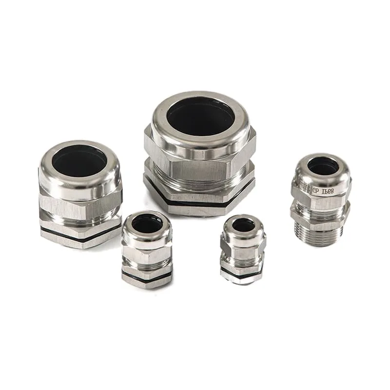
<img alt="五個金屬電纜密封接頭，接頭本體與電纜開口尺寸各不相同" src="/images/blog/the-ultimate-guide-to-cable-gland-sizing-how-to-match-glands-to-cable-diameters/cable-gland-size-family.webp" srcset="/images/blog/the-ultimate-guide-to-cable-gland-sizing-how-to-match-glands-to-cable-diameters/cable-gland-size-family-600.webp 600w, /images/blog/the-ultimate-guide-to-cable-gland-sizing-how-to-match-glands-to-cable-diameters/cable-gland-size-family.webp 800w" sizes="(max-width: 640px) 100vw, 800px" width="800" height="800" loading="lazy" decoding="async" />
<figcaption>圖中五個接頭本體的電纜開口與安裝尺寸明顯不同，因此每個候選接頭仍須分別查核其尺寸表列項及圖面。</figcaption>
<h2 id="convert-nominal-od-and-tolerance-into-a-cable-interval">將標稱外徑與公差換算為電纜尺寸區間</h2>
<p><strong>標稱外徑是中心值或尺寸標示，不等於允許範圍內所有產品的尺寸。</strong>我會採用圖面列出的上下限。若上下公差幅度不同，應保留其不對稱性。不要改用推測的百分比。</p>
<p>對於成品電纜標稱直徑<span class="article-math article-math-inline" data-latex="D_{\text{nom}}"><span class="katex"><math xmlns="http://www.w3.org/1998/Math/MathML"><semantics><mrow><msub><mi>D</mi><mtext>nom</mtext></msub></mrow><annotation encoding="application/x-tex">D_{\text{nom}}</annotation></semantics></math></span></span>、下公差幅度<span class="article-math article-math-inline" data-latex="T_{-}"><span class="katex"><math xmlns="http://www.w3.org/1998/Math/MathML"><semantics><mrow><msub><mi>T</mi><mo lspace="0em" rspace="0em">−</mo></msub></mrow><annotation encoding="application/x-tex">T_{-}</annotation></semantics></math></span></span>，上公差幅度<span class="article-math article-math-inline" data-latex="T_{+}"><span class="katex"><math xmlns="http://www.w3.org/1998/Math/MathML"><semantics><mrow><msub><mi>T</mi><mo lspace="0em" rspace="0em">+</mo></msub></mrow><annotation encoding="application/x-tex">T_{+}</annotation></semantics></math></span></span>，計算如下：</p>
<div class="article-math article-math-display" data-latex="D_{\min}=D_{\text{nom}}-T_{-},\qquad D_{\max}=D_{\text{nom}}+T_{+}"><span class="katex"><math xmlns="http://www.w3.org/1998/Math/MathML" display="block"><semantics><mrow><msub><mi>D</mi><mi>min</mi><mo>⁡</mo></msub><mo>=</mo><msub><mi>D</mi><mtext>nom</mtext></msub><mo>−</mo><msub><mi>T</mi><mo lspace="0em" rspace="0em">−</mo></msub><mo separator="true">,</mo><mspace width="2em"/><msub><mi>D</mi><mi>max</mi><mo>⁡</mo></msub><mo>=</mo><msub><mi>D</mi><mtext>nom</mtext></msub><mo>+</mo><msub><mi>T</mi><mo lspace="0em" rspace="0em">+</mo></msub></mrow><annotation encoding="application/x-tex">D_{\min}=D_{\text{nom}}-T_{-},\qquad D_{\max}=D_{\text{nom}}+T_{+}</annotation></semantics></math></span></div>
<p>其中，<span class="article-math article-math-inline" data-latex="D_{\min}"><span class="katex"><math xmlns="http://www.w3.org/1998/Math/MathML"><semantics><mrow><msub><mi>D</mi><mi>min</mi><mo>⁡</mo></msub></mrow><annotation encoding="application/x-tex">D_{\min}</annotation></semantics></math></span></span> 及 <span class="article-math article-math-inline" data-latex="D_{\max}"><span class="katex"><math xmlns="http://www.w3.org/1998/Math/MathML"><semantics><mrow><msub><mi>D</mi><mi>max</mi><mo>⁡</mo></msub></mrow><annotation encoding="application/x-tex">D_{\max}</annotation></semantics></math></span></span>分別是以相同長度單位表示的電纜最小與最大外徑。我會用此計算將圖面限值帶入比較。它不會預測護套壓縮量或密封壓力。將尺寸記號、單位、公差方向及版次一併記錄於結果中。接頭資料與說明會界定電纜範圍的適用方式。</p>
<p>例如，若電纜圖面標示標稱外徑 12.0 mm、公差 +0.4 mm 及 -0.2 mm，完整區間為 11.8 至 12.4 mm。現場讀值 12.1 mm 落在此區間內，但這不會消除未來電纜批次適用的圖面限值。若數個核准電纜來源的限值不同，應分別檢查各來源；只有在專案確實允許互換時，才使用合併後的極值。</p>
<p>三種不同界限應分開處理：圖面公差表示允許的電纜尺寸；抽樣極值表示實際量測的零件與位置；量測不確定度則說明結果的限制。由圓周長換算出的 12.00 mm，不能取代 11.8 至 12.4 mm 的圖面區間。接近接頭限值時，應使用規定的判定規則及適當的量測能力；不可自行增加容許量，也不可將接近界限的結果修約到範圍內。</p>
<h2 id="compare-the-full-cable-interval-with-the-gland-range">比較完整電纜區間與接頭範圍</h2>
<p><strong>電纜密封範圍</strong>是針對確切接頭、密封件及嵌件配置所聲明的最小至最大外徑區間。只有兩個邊界都落入該聲明範圍內時，電纜區間才符合。令 <span class="article-math article-math-inline" data-latex="G_{\min}"><span class="katex"><math xmlns="http://www.w3.org/1998/Math/MathML"><semantics><mrow><msub><mi>G</mi><mi>min</mi><mo>⁡</mo></msub></mrow><annotation encoding="application/x-tex">G_{\min}</annotation></semantics></math></span></span> 及 <span class="article-math article-math-inline" data-latex="G_{\max}"><span class="katex"><math xmlns="http://www.w3.org/1998/Math/MathML"><semantics><mrow><msub><mi>G</mi><mi>max</mi><mo>⁡</mo></msub></mrow><annotation encoding="application/x-tex">G_{\max}</annotation></semantics></math></span></span> 分別為該範圍的電纜最小與最大外徑。初步尺寸條件如下：</p>
<div class="article-math article-math-display" data-latex="G_{\min}\le D_{\min}\quad\text{且}\quad D_{\max}\le G_{\max}"><span class="katex"><math xmlns="http://www.w3.org/1998/Math/MathML" display="block"><semantics><mrow><msub><mi>G</mi><mi>min</mi><mo>⁡</mo></msub><mo>≤</mo><msub><mi>D</mi><mi>min</mi><mo>⁡</mo></msub><mspace width="1em"/><mtext>且</mtext><mspace width="1em"/><msub><mi>D</mi><mi>max</mi><mo>⁡</mo></msub><mo>≤</mo><msub><mi>G</mi><mi>max</mi><mo>⁡</mo></msub></mrow><annotation encoding="application/x-tex">G_{\min}\le D_{\min}\quad\text{且}\quad D_{\max}\le G_{\max}</annotation></semantics></math></span></div>
<p>下側裕度為 <span class="article-math article-math-inline" data-latex="M_{L}=D_{\min}-G_{\min}"><span class="katex"><math xmlns="http://www.w3.org/1998/Math/MathML"><semantics><mrow><msub><mi>M</mi><mi>L</mi></msub><mo>=</mo><msub><mi>D</mi><mi>min</mi><mo>⁡</mo></msub><mo>−</mo><msub><mi>G</mi><mi>min</mi><mo>⁡</mo></msub></mrow><annotation encoding="application/x-tex">M_{L}=D_{\min}-G_{\min}</annotation></semantics></math></span></span>，上側裕度為 <span class="article-math article-math-inline" data-latex="M_{U}=G_{\max}-D_{\max}"><span class="katex"><math xmlns="http://www.w3.org/1998/Math/MathML"><semantics><mrow><msub><mi>M</mi><mi>U</mi></msub><mo>=</mo><msub><mi>G</mi><mi>max</mi><mo>⁡</mo></msub><mo>−</mo><msub><mi>D</mi><mi>max</mi><mo>⁡</mo></msub></mrow><annotation encoding="application/x-tex">M_{U}=G_{\max}-D_{\max}</annotation></semantics></math></span></span>。正值表示電纜區間在該側位於聲明範圍內。零表示電纜到達聲明邊界。負值指出未符合的是哪一側。不要自行增加 10% 或 15% 的容許量；應直接比較文件記載的限值，並遵循製造商對端點採包含或排除的規則。</p>
<p>以上述 11.8 至 12.4 mm 電纜為例，假設某接頭範圍為 10.0 至 14.0 mm，則其涵蓋完整區間。下側裕度為 11.8 − 10.0 = 1.8 mm；上側裕度為 14.0 − 12.4 = 1.6 mm。因此上側的尺寸裕度較小。另一個 12.0 至 16.0 mm 的範圍則在下限處不符合：11.8 − 12.0 = −0.2 mm。即使實測樣品 12.1 mm 落在兩個範圍內，這仍指出尺寸不匹配。接受任一候選接頭前，應確認兩個範圍指的是相同外護套層與相同密封件選項。第一個結果只確認直徑區間被涵蓋；並未確立密封相容性、固定能力、溫度適用性、安裝配合或確切配置的性能。</p>
<table>
<thead>
<tr>
<th>比較項目</th>
<th>輸入值</th>
<th>記錄結果</th>
</tr>
</thead>
<tbody>
<tr>
<td>電纜下限與接頭下限</td>
<td><span class="article-math article-math-inline" data-latex="D_{\min}"><span class="katex"><math xmlns="http://www.w3.org/1998/Math/MathML"><semantics><mrow><msub><mi>D</mi><mi>min</mi><mo>⁡</mo></msub></mrow><annotation encoding="application/x-tex">D_{\min}</annotation></semantics></math></span></span> 及 <span class="article-math article-math-inline" data-latex="G_{\min}"><span class="katex"><math xmlns="http://www.w3.org/1998/Math/MathML"><semantics><mrow><msub><mi>G</mi><mi>min</mi><mo>⁡</mo></msub></mrow><annotation encoding="application/x-tex">G_{\min}</annotation></semantics></math></span></span></td>
<td>下側裕度：通過或不通過</td>
</tr>
<tr>
<td>電纜上限與接頭上限</td>
<td><span class="article-math article-math-inline" data-latex="D_{\max}"><span class="katex"><math xmlns="http://www.w3.org/1998/Math/MathML"><semantics><mrow><msub><mi>D</mi><mi>max</mi><mo>⁡</mo></msub></mrow><annotation encoding="application/x-tex">D_{\max}</annotation></semantics></math></span></span> 及 <span class="article-math article-math-inline" data-latex="G_{\max}"><span class="katex"><math xmlns="http://www.w3.org/1998/Math/MathML"><semantics><mrow><msub><mi>G</mi><mi>max</mi><mo>⁡</mo></msub></mrow><annotation encoding="application/x-tex">G_{\max}</annotation></semantics></math></span></span></td>
<td>上側裕度：通過或不通過</td>
</tr>
<tr>
<td>邊界判定方式</td>
<td>產品範圍說明或指示</td>
<td>包含端點、排除端點或尚未釐清</td>
</tr>
<tr>
<td>電纜形狀</td>
<td>長軸與短軸外徑、凸肋、平面及過渡段</td>
<td>圓形範圍是否適用，或是否需要特殊密封件</td>
</tr>
<tr>
<td>確切配置</td>
<td>接頭系列、尺寸、嵌件、密封件及版次</td>
<td>與候選零件相連結的資料列</td>
</tr>
</tbody>
</table>
<p><a class="article-tool-card article-tool-card-link" href="/zh-hant/resource-center/tools/cable-od-tolerance-calculator/" aria-label="電纜外徑公差計算器"><span class="article-tool-card-index">工具</span><span class="article-tool-card-kicker">電纜尺寸</span><strong class="article-tool-card-title">電纜外徑公差計算器</strong><span class="article-tool-card-copy">輸入電纜圖面的標稱外徑及分開列出的正、負公差，再將計算所得的上下限與確切接頭所聲明的密封範圍比較。</span><span class="article-tool-card-formula">Dmin = Dnom − T−; Dmax = Dnom + T+</span><span class="article-tool-card-inputs" aria-label="計算器輸入項目"><em>電纜標稱外徑</em><em>上限公差</em><em>下限公差</em></span><span class="article-tool-card-action">開啟計算器 <span aria-hidden="true">-&gt;</span></span></a></p><h2 id="keep-armoured-and-non-round-cable-dimensions-separate">鎧裝與非圓電纜尺寸應分開記錄</h2>
<p><strong>單一整體外徑無法描述特殊接頭所處理的所有層。</strong>對於鎧裝引入口，我會分別記錄外護套直徑、鎧裝直徑與類型、內墊層或內護套直徑，以及剝除尺寸。內墊層位於鎧裝之下。電磁相容性（EMC）接頭也可能需要已處理的屏蔽接觸直徑。每項數值都應對應至其作用部件。</p>
<p>不要擴大外護套範圍來掩蓋鎧裝或內墊層不匹配。確認哪些<a href="/zh-hant/blog/armored-vs-unarmored-cable-glands-which-one-do-you-really-need/">鎧裝或非鎧裝電纜層</a>需要密封、夾持或等電位連接，再確認所選接頭圖面顯示各已處理層位於其預定介面。</p>
<p>對橢圓形電纜，應將量測紀錄中的長軸與短軸數值帶入產品比較。長軸數值決定能否通過圓形開口，短軸數值則會影響圓形密封件與電纜的接觸。扁平、帶狀、波紋及多電纜引入口需要適用於該幾何形狀的密封件。不可將<a href="/zh-hant/blog/what-are-flat-cable-glands-and-when-should-you-use-them-for-specialized-installations/">扁平電纜輪廓</a>簡化為一個圓等效直徑，因為這種簡化可能掩蓋角落間隙。</p>
<h2 id="match-the-gland-to-the-enclosure-entry-and-wall">使接頭配合外殼引入口與壁面</h2>
<p><strong>電纜配合並不能決定引入口螺紋或孔徑。</strong>我會另外辨識螺紋孔、搭配鎖緊螺帽的無螺紋通孔、轉接頭或縮徑接頭，以及特定開口系統。取得其尺寸與公差、壁厚、平整的密封承靠面、入口密封件、配件、內部間隙及可用嚙合長度。</p>
<p><a href="https://webstore.iec.ch/en/publication/2112">IEC 60423:2007</a>規定導管外徑及相關螺紋與接頭尺寸。將其用於公制電纜管理螺紋，再依接頭圖面確認電纜範圍、突出長度、密封件及安裝方式。</p>
<p>我會先從外殼文件確認受配合螺紋或無螺紋通孔配置。檢查完整外螺紋入口、可用螺紋、導入段及密封面。確認<a href="/zh-hant/blog/pg-vs-metric-vs-npt-threads-which-cable-gland-threading-system-should-you-choose/">公制、PG 或 NPT 結構</a>：PG 與 NPT 是不同的螺紋系統；NPT 指美制錐管螺紋。指定加工方式前，先區分<a href="/zh-hant/blog/how-to-select-the-correct-entry-hole-size-for-your-cable-gland/">螺紋孔與無螺紋通孔</a>。</p>
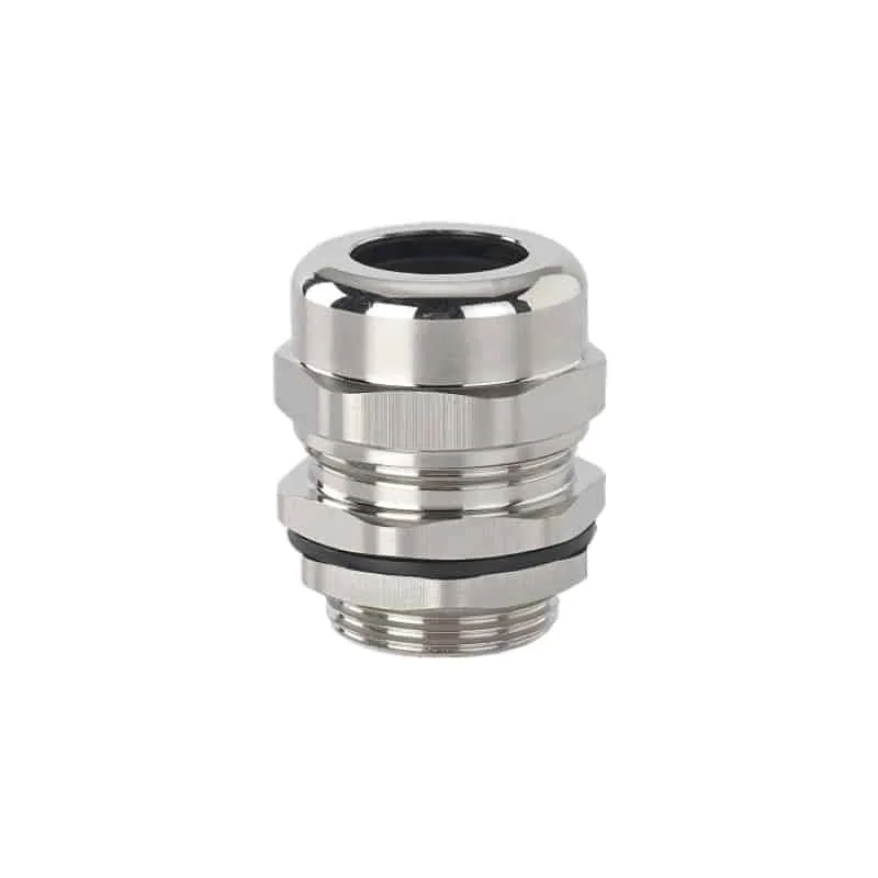
<img alt="金屬電纜密封接頭，顯示其電纜開口、壓帽、本體平面、入口密封件及外螺紋安裝螺紋" src="/images/blog/the-ultimate-guide-to-cable-gland-sizing-how-to-match-glands-to-cable-diameters/gland-cable-entry-interfaces.webp" srcset="/images/blog/the-ultimate-guide-to-cable-gland-sizing-how-to-match-glands-to-cable-diameters/gland-cable-entry-interfaces-600.webp 600w, /images/blog/the-ultimate-guide-to-cable-gland-sizing-how-to-match-glands-to-cable-diameters/gland-cable-entry-interfaces.webp 800w" sizes="(max-width: 640px) 100vw, 800px" width="800" height="800" loading="lazy" decoding="async" />
<figcaption>電纜由上方的壓帽進入；外螺紋與入口密封件則由下方安裝至外殼。</figcaption>
<p>對無螺紋通孔，我會將壁面、入口密封件、墊圈、任何接地片及所需螺帽嚙合長度納入螺紋長度計算。對螺紋孔引入口，則檢查可用內螺紋深度、導入段、不完整尾端螺紋或螺紋收尾段、密封面及底部間隙。先確認完整組裝，再選擇標準或長螺紋結構。</p>
<h2 id="carry-the-size-decision-through-installation">讓尺寸選型決策貫穿安裝過程</h2>
<p><strong>安裝時應維持所選電纜及各介面的狀態。</strong>切割前，我會確認電纜、接頭料號、散件、引入口及說明。若電纜來源、嵌件、轉接頭、鎖緊螺帽或墊圈變更，尺寸判定結果也可能改變。</p>
<ol>
<li>檢查密封區是否有切口、平面、污染、舊壓痕，或會改變局部表面的印字。</li>
<li>穿入電纜時不要刮傷護套或使密封件零件移位。確認連接器或已處理的端頭能通過每個內部孔徑。</li>
<li>依圖面指定的介面定位鎧裝、內墊層、屏蔽及護套。不要讓外護套密封件落在已剝除或有階差的區域。</li>
<li>將入口密封件置於指定的外殼表面，鎖緊時保持接頭對齊。</li>
<li>使用指定工具並鎖緊至規定終點。通用扭矩值不能取代所選尺寸、材料、螺紋、密封件及潤滑狀態所對應的說明。</li>
<li>支撐電纜，避免其重量與彎曲使接頭受擾。佈線後重新檢查密封區及安裝接合處。</li>
</ol>
<p><a href="https://webstore.iec.ch/en/publication/2452">IEC 60529:1989+A1:1999+A2:2013</a>在其範圍內對外殼防護進行分類。其侵入防護（IP）代碼適用於受評估組件。電纜與接頭標稱尺寸相符，並不能證明該結果。我會保留經測試的引入口配置，並遵循產品及外殼說明。</p>
<h2 id="correct-common-sizing-failures-at-the-right-interface">在正確介面處理常見尺寸選型失誤</h2>
<p><strong>尺寸選型失誤</strong>是已識別的電纜或外殼介面不匹配。電纜小於接頭最小值時，可能無法達到預期密封接觸；大於最大值時，可能無法穿過，或超出密封件幾何範圍。應選擇相容的接頭或核准嵌件，不要強行裝配。</p>
<p>若電纜配合檢查通過但安裝介面不符，請採用核准的接頭變型或有文件依據的轉接配置。下一個較大的螺紋尺寸不一定能提供所需電纜範圍。遇到鎧裝不匹配時，我會回到各層尺寸分別檢查；對扁平、明顯橢圓、帶肋、波紋或成束電纜，則選擇適合其輪廓的密封件。</p>
<p>若量測結果與圖面不一致，應先釐清電纜識別、狀態與量測方法，再選擇不同接頭。將實測極值與受控的電纜限值一併保留。更換電纜、嵌件或入口配件會改變比較結果，並須重新檢查受影響的尺寸。</p>
<h2 id="conclusion">結論</h2>
<p>電纜密封接頭尺寸選型從成品外護套及其完整外徑區間開始。換算前先辨識量具刻度：一般圓周長讀值需除以 pi；OD 直徑量帶顯示的讀值已是直徑。保留實測極值與圖面限值，再將電纜的上下邊界與確切接頭配置比較。鎧裝、內墊層、屏蔽、貫通孔及非圓形幾何各有不同作用，應分別記錄。</p>
<p>電纜端的檢查通過後，我會確認安裝方式、壁厚、配件及安裝空間。將這些資訊放入同一份比較紀錄，並在下單或安裝前依據現行電纜資料、接頭圖面及說明核對每個介面。</p>
<h2 id="faqs-about-cable-gland-sizing">電纜密封接頭尺寸選型常見問題</h2>
<h3 id="is-an-m20-cable-gland-made-for-a-20-mm-cable">M20 電纜密封接頭是為 20 mm 電纜設計的嗎？</h3>
<p>不是。M20 表示標稱公制引入口螺紋尺寸，並非電纜密封範圍。不同 M20 接頭系列或密封嵌件可配用不同電纜直徑。查閱確切產品資料列與圖面，將電纜完整外徑區間與聲明範圍比較，並另行檢查外殼引入口。</p>
<h3 id="should-i-divide-a-diameter-tape-reading-by-pi">直徑量帶的讀值需要除以 pi 嗎？</h3>
<p>不需要。OD 直徑量帶會依其校正過的纏繞刻度直接顯示直徑。只有原始數值確實是圓周長時才除以 pi。確認刻度與單位，保留原始讀值，並將長軸與短軸尺寸和任何圓等效結果一併記錄。</p>
<h3 id="can-the-cable-sit-exactly-on-a-gland-range-boundary">電纜尺寸可以剛好落在接頭範圍邊界上嗎？</h3>
<p>遵循產品資料或安裝說明中的邊界規則。列出的限值可能包含端點、排除端點，或受密封件／嵌件選項限定。將零裕度記錄為邊界狀態，並核實確切配置；不要用四捨五入或假設的容許量把數值往範圍內移。</p>
<h3 id="how-should-i-size-a-gland-for-an-oval-cable">橢圓形電纜的接頭尺寸應如何選擇？</h3>
<p>在相同截面位置測量長軸與短軸直徑，並記錄其沿密封區的變化。長軸直徑決定能否通過圓形孔徑，兩個方向都會影響密封接觸。只有產品資料允許該幾何形狀時才使用圓形接頭；否則應選擇外形相符的密封方案。</p>
<h3 id="does-a-cable-diameter-match-prove-an-ip-rating">電纜直徑相符能證明 IP 防護等級嗎？</h3>
<p>不能。直徑相符僅是尺寸初篩。適用的 IP 結果取決於受評估的外殼、接頭、電纜、入口密封件、安裝表面、組裝狀態及試驗條件。確認確切配置與安裝說明，再依專案要求驗證完成後的外殼。</p>
<h3 id="sources-and-technical-references">來源與技術參考資料</h3>
<ul>
<li>
<p><a href="https://webstore.iec.ch/en/publication/7034">IEC 62444:2010，電氣裝置用電纜密封接頭</a>，存取日期 2026-10-22。</p>
</li>
<li>
<p><a href="https://www.nist.gov/metrology/metrological-traceability">NIST，計量可追溯性</a>，存取日期 2026-10-22。</p>
</li>
<li>
<p><a href="https://webstore.iec.ch/en/publication/2112">IEC 60423:2007，導管外徑及螺紋尺寸</a>，存取日期 2026-10-22。</p>
</li>
<li>
<p><a href="https://webstore.iec.ch/en/publication/2452">IEC 60529 合併版，外殼提供的防護等級</a>，存取日期 2026-10-22。</p>
</li>
<li>
<p><a href="https://knowledge.bsigroup.com/products/geometrical-product-specifications-gps-dimensional-tolerancing-part-1-linear-sizes">ISO 14405-1:2025，線性尺寸的尺寸公差</a>，存取日期 2026-10-22。</p>
</li>
<li>
<p><a href="https://tsapps.nist.gov/publication/get_pdf.cfm?pub_id=917404">NISTIR 8028，長度校正選定實驗室與量測實務及程序，SOP 23</a>，存取日期 2026-10-22。</p>
</li>
<li>
<p><a href="https://www.npl.co.uk/resources/gpgs/callipers-micrometers">NPL，良好實務指南 40：卡尺與千分尺</a>，存取日期 2026-10-22。</p>
</li>
<li>
<p><a href="https://www.nist.gov/pml/special-publication-811/nist-guide-si-chapter-7-rules-and-style-conventions-expressing-values">NIST SP 811，第 7 章：量值表達方式</a>，存取日期 2026-10-22。</p>
</li>
</ul>