# 保護敏感電子設備：EMC 屏蔽指南

> Source: https://chinacableglands.com/zh-hant/blog/protecting-sensitive-electronics-how-emc-shielding-solutions-prevent-million-dollar-equipment-failures/
> Language: zh-Hant
> Publisher: 倍拓電纜接頭
> Author: Victor Huang
> Published: 2026-01-27
> Updated: 2026-10-22

追蹤電纜屏蔽層經過 EMC 電纜密封接頭的路徑，解讀 dB 振幅比與功率比，並區分元件量測與設備 EMC 佐證。

<p><strong>EMC 屏蔽方案若能切斷通往易受影響電路的耦合路徑，便可保護敏感電子設備。</strong>EMC 是電磁相容性（electromagnetic compatibility）的縮寫：設備必須在其電磁環境中正常運作，且不造成不可接受的干擾。在電纜引入口，我會追蹤從電纜屏蔽層經接觸元件與接頭本體到外殼的導電路徑。</p>
<p>屏蔽層是電纜的導電屏蔽層；耦合路徑是干擾到達電路的路線。設備抗擾度——在干擾期間維持運作的能力——取決於干擾源、該路徑、受影響電路及適用的設備測試。以分貝表示的結果也須考量其量測物理量及參考值。</p>
<p>電磁干擾可能使生產停擺、量測失真、觸發重設，或損壞設備。成本取決於系統的重要性，以及停擺時間。我會先找出電纜引入口處屏蔽邊界的中斷點，再確認元件佐證是否適用於完成組裝的設備。</p>
<blockquote>
<p><strong>重點摘要</strong></p>
<ul>
<li>先從干擾源、耦合路徑及易受影響功能著手。電纜引入方案可處理穿越該引入口的路徑。</li>
<li>將電纜屏蔽層、接觸區、接頭本體、面板介面與外殼視為一條相連路徑，並留意其中多個可能失效的位置。</li>
<li>「360 度接觸」描述的是幾何形狀；分貝數值、頻率範圍及完成設備的結果，分別來自各自的測試。</li>
<li>將參考值/殘餘值振幅比以 20 log 換算，功率比則以 10 log 換算；同時保留頻率、測試設定與物理量基準。</li>
<li>EMC、保護等電位連接、侵入防護、保持能力與環境耐久性應分開主張。</li>
</ul>
</blockquote>
<h2 id="the-cable-entry-is-part-of-the-shielding-boundary">電纜引入口是屏蔽邊界的一部分</h2>
<p><strong>屏蔽邊界</strong>是一種可降低干擾與易受影響電路之間耦合的結構。它可以是導電結構或電磁結構。電纜屏蔽層、端接、外殼、接縫、門板及濾波器都可能構成其一部分。當電纜屏蔽層穿過外殼壁時，電纜密封接頭可延續該邊界，也可能留下中斷處。</p>
<p>2023 年的 <a href="https://webstore.iec.ch/en/publication/70473">IEC TR 61000-1-1 公開範圍</a>以干擾源、易受影響設備或系統及耦合機制為 EMC 建立框架。該範圍區分標準測試，與製造地點或已安裝地點的量測。我在評估電纜密封接頭時會保留這項區分。元件可能依預期運作，但導體、接縫、通氣口、連接器或內部配置仍可能形成另一條通往設備內的主要路徑。每個穿越邊界的位置都須個別評估。</p>
<p>更廣泛的 <a href="/zh-hant/blog/what-is-electromagnetic-compatibility-emc-shielding-and-why-does-your-business-need-it/">EMC 屏蔽基礎指南</a>說明這些層面。在電纜引入口，相關層面是接頭處屏蔽層至外殼的轉接介面。</p>
<table>
<thead>
<tr>
<th>路徑組成部分</th>
<th>引入口處的預定功能</th>
<th>可能使路徑中斷的因素</th>
</tr>
</thead>
<tbody>
<tr>
<td>電纜屏蔽層</td>
<td>將屏蔽電流導至端接區</td>
<td>屏蔽層選錯、編織層或金屬箔受損、準備方式不適當</td>
</tr>
<tr>
<td>接觸元件</td>
<td>使指定屏蔽表面與電纜密封接頭導通</td>
<td>接觸範圍錯誤、未形成完整圓周接觸、污染、移動</td>
</tr>
<tr>
<td>導電接頭本體</td>
<td>讓路徑穿過電纜引入口</td>
<td>非導電型式、介面鬆動、轉接頭不適用</td>
</tr>
<tr>
<td>面板介面</td>
<td>將電纜密封接頭組件連接至外殼邊界</td>
<td>油漆、陽極處理層、腐蝕、絕緣墊圈、貼合不良</td>
</tr>
<tr>
<td>外殼</td>
<td>延續電子設備周圍的屏蔽邊界</td>
<td>開放的接縫、門板、通氣口或其他貫穿處</td>
</tr>
</tbody>
</table>
<p>2023 年 <a href="https://webstore.iec.ch/en/publication/61223">IEC TR 61000-5-1 範圍</a>說明一般安裝層級的 EMC 措施。該系列的整體安裝指南涵蓋電纜、等電位連接、接地、濾波器及屏蔽外殼等主題。EMC 電纜密封接頭在此系統的一個介面上發揮作用。</p>
<h2 id="how-does-an-emc-cable-gland-preserve-screen-continuity">EMC 電纜密封接頭如何維持屏蔽層連續性？</h2>
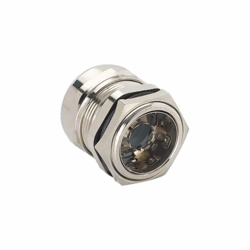
<p><strong>EMC 電纜密封接頭</strong>會與指定電纜屏蔽層形成受控接觸，並可讓導電路徑跨越外殼引入口。它也有機械與環境方面的功能要求。屏蔽功能取決於電氣介面。依產品設計，接觸系統可能採用彈簧指、夾持環、錐體，或製造商規定的其他結構。</p>
<p>我會只在說明要求露出屏蔽層的位置處理護套。請確認接觸元件符合處理後屏蔽層的直徑與結構。使用指定的屏蔽表面；排流線（用於連接部分箔屏蔽的導線）不能自動取代該接觸。</p>
<p>接著確認從接頭本體到外殼的路徑，或透過指定的導電轉接頭及等電位連接結構形成的路徑。油漆、非導電面板或不適用的配件可能中斷這條高頻連接。即使電氣路徑已中斷，鎖緊螺帽仍可能牢牢固定接頭。</p>
<img alt="金屬 EMC 電纜密封接頭的外觀，可見電纜引入口內的徑向彈簧指。" src="/images/blog/protecting-sensitive-electronics-how-emc-shielding-solutions-prevent-million-dollar-equipment-failures/wp-emc-gland-radial-spring-contact.webp" width="800" height="800" loading="lazy" decoding="async">
<p><em>金屬接頭內部的徑向彈簧指會在處理後的電纜屏蔽層周圍，形成環周接觸區。</em></p>
<p>這份 <a href="/zh-hant/blog/how-do-you-choose-the-right-emc-cable-gland-to-eliminate-electromagnetic-interference-problems/">EMC 電纜密封接頭選型指南</a>將兩種範圍分開說明。一種涵蓋電纜外徑，另一種涵蓋屏蔽層接觸範圍。兩者都可能適用於同一個接頭，但代表不同介面。電纜可能符合環境密封範圍，而處理後的屏蔽層直徑卻超出接觸系統所標示的範圍。</p>
<h2 id="shield-continuity-across-the-cable-entry-interface">跨越電纜引入口介面的屏蔽連續性</h2>
<p><strong>屏蔽連續性</strong>是指指定導電路徑沒有非預期的絕緣中斷。路徑從電纜屏蔽層延伸至外殼。下方示意圖標示該路徑中的四個介面。請依確切接頭圖面及電纜準備說明，確定接觸長度與組裝幾何形狀。</p>
<figure class="blog-chart" style="container-type: inline-size;">
<svg xmlns="http&#58;//www.w3.org/2000/svg" viewBox="0 0 480 1374.15" role="img" aria-labelledby="emc-entry-path-title emc-entry-path-desc" style="font-family:var(--font-body); width: 100% !important; max-width: 100% !important; height: auto !important;" id="cg-typography-4f241fc2b16c0427">
<style>
#cg-typography-4f241fc2b16c0427 { --svg-body-screen: 17px; }
@media (max-width: 760px) { #cg-typography-4f241fc2b16c0427 { --svg-body-screen: 16px; } }
</style>
<title id="emc-entry-path-title">EMC 電纜引入介面中的電纜屏蔽層連續性</title>
<desc id="emc-entry-path-desc">垂直示意圖沿導電路徑追蹤，從電纜屏蔽層經環周接觸與接頭本體到外殼壁；接著列出五項中斷線索，並區分直流連續性量測與射頻組件量測。</desc>
<defs>
<marker id="emc-entry-path-arrow" markerWidth="8" markerHeight="8" refX="7" refY="4" orient="auto">
<path d="M0 0L8 4L0 8Z" fill="var(--color-primary)"/>
</marker>
</defs>
<text x="32" y="36" fill="var(--color-carbon)" font-size="24" font-weight="700" style="font-size: calc(22px * 480px / 100cqw) !important;">外殼引入口處的</text>
<text x="32" y="68.1478" fill="var(--color-carbon)" font-size="24" font-weight="700" style="font-size: calc(22px * 480px / 100cqw) !important;">屏蔽電流路徑</text>
<text x="32" y="100.148" fill="var(--color-graphite)" font-size="18" style="font-size: calc(var(--svg-body-screen) * 480px / 100cqw) !important;">沿著指定電纜引入組件</text>
<text x="32" y="126.148" fill="var(--color-graphite)" font-size="18" style="font-size: calc(var(--svg-body-screen) * 480px / 100cqw) !important;">逐一追蹤導電介面。</text>
<rect x="32" y="142.148" width="416" height="120" rx="14" fill="var(--surface-card)" stroke="var(--color-cloud)" stroke-width="2"/>
<text x="56" y="180.148" fill="var(--color-carbon)" font-size="20" font-weight="700" style="font-size: calc(18px * 480px / 100cqw) !important;">1 電纜屏蔽層</text>
<text x="56" y="216.148" fill="var(--color-graphite)" font-size="18" style="font-size: calc(var(--svg-body-screen) * 480px / 100cqw) !important;">比對確切結構及</text>
<text x="56" y="242.148" fill="var(--color-graphite)" font-size="18" style="font-size: calc(var(--svg-body-screen) * 480px / 100cqw) !important;">處理後的屏蔽層直徑。</text>
<path d="M240 262.148 V296.148" stroke="var(--color-primary)" stroke-width="4" marker-end="url(#emc-entry-path-arrow)"/>
<rect x="32" y="314.148" width="416" height="142" rx="14" fill="var(--surface-card)" stroke="var(--color-primary)" stroke-width="3"/>
<text x="56" y="354.148" fill="var(--color-carbon)" font-size="20" font-weight="700" style="font-size: calc(18px * 480px / 100cqw) !important;">2 環周接觸</text>
<text x="56" y="390.148" fill="var(--color-graphite)" font-size="18" style="font-size: calc(var(--svg-body-screen) * 480px / 100cqw) !important;">彈簧或夾具會接觸指定的</text>
<text x="56" y="416.148" fill="var(--color-graphite)" font-size="18" style="font-size: calc(var(--svg-body-screen) * 480px / 100cqw) !important;">屏蔽層表面並環繞其圓周。</text>
<path d="M240 456.148 V490.148" stroke="var(--color-primary)" stroke-width="4" marker-end="url(#emc-entry-path-arrow)"/>
<rect x="32" y="508.148" width="416" height="122" rx="14" fill="var(--surface-card)" stroke="var(--color-cloud)" stroke-width="2"/>
<text x="56" y="546.148" fill="var(--color-carbon)" font-size="20" font-weight="700" style="font-size: calc(18px * 480px / 100cqw) !important;">3 導電接頭本體</text>
<text x="56" y="582.148" fill="var(--color-graphite)" font-size="18" style="font-size: calc(var(--svg-body-screen) * 480px / 100cqw) !important;">讓路徑穿過螺紋、</text>
<text x="56" y="608.148" fill="var(--color-graphite)" font-size="18" style="font-size: calc(var(--svg-body-screen) * 480px / 100cqw) !important;">轉接頭及指定配件。</text>
<path d="M240 630.148 V664.148" stroke="var(--color-primary)" stroke-width="4" marker-end="url(#emc-entry-path-arrow)"/>
<rect x="32" y="682.148" width="416" height="142" rx="14" fill="var(--color-ash)" stroke="var(--color-primary)" stroke-width="3"/>
<text x="56" y="720.148" fill="var(--color-carbon)" font-size="20" font-weight="700" style="font-size: calc(18px * 480px / 100cqw) !important;">4 外殼壁與</text>
<text x="56" y="746.148" fill="var(--color-carbon)" font-size="20" font-weight="700" style="font-size: calc(18px * 480px / 100cqw) !important;">屏蔽邊界</text>
<text x="56" y="786.148" fill="var(--color-graphite)" font-size="18" style="font-size: calc(var(--svg-body-screen) * 480px / 100cqw) !important;">讓路徑完整穿過指定的</text>
<text x="56" y="812.148" fill="var(--color-graphite)" font-size="18" style="font-size: calc(var(--svg-body-screen) * 480px / 100cqw) !important;">導電面板介面。</text>
<rect x="32" y="854.148" width="416" height="330" rx="14" fill="var(--surface-card)" stroke="var(--color-cloud)" stroke-width="2"/>
<text x="56" y="894.148" fill="var(--color-carbon)" font-size="20" font-weight="700" style="font-size: calc(18px * 480px / 100cqw) !important;">五項中斷線索</text>
<circle cx="64" cy="932.148" r="6" fill="var(--color-primary)"/>
<text x="84" y="938.148" fill="var(--color-graphite)" font-size="18" style="font-size: calc(16px * 480px / 100cqw) !important;">屏蔽層選用錯誤</text>
<circle cx="64" cy="974.148" r="6" fill="var(--color-primary)"/>
<text x="84" y="980.148" fill="var(--color-graphite)" font-size="18" style="font-size: calc(16px * 480px / 100cqw) !important;">處理後的屏蔽層直徑</text>
<text x="84" y="1006.15" fill="var(--color-graphite)" font-size="18" style="font-size: calc(16px * 480px / 100cqw) !important;">超出接觸範圍</text>
<circle cx="64" cy="1044.15" r="6" fill="var(--color-primary)"/>
<text x="84" y="1050.15" fill="var(--color-graphite)" font-size="18" style="font-size: calc(16px * 480px / 100cqw) !important;">介面鬆動或受到污染</text>
<circle cx="64" cy="1086.15" r="6" fill="var(--color-primary)"/>
<text x="84" y="1092.15" fill="var(--color-graphite)" font-size="18" style="font-size: calc(16px * 480px / 100cqw) !important;">路徑中使用了非導電轉接頭</text>
<circle cx="64" cy="1128.15" r="6" fill="var(--color-primary)"/>
<text x="84" y="1134.15" fill="var(--color-graphite)" font-size="18" style="font-size: calc(16px * 480px / 100cqw) !important;">預定的面板接觸部位仍有</text>
<text x="84" y="1160.15" fill="var(--color-graphite)" font-size="18" style="font-size: calc(var(--svg-body-screen) * 480px / 100cqw) !important;">塗層殘留</text>
<rect x="32" y="1208.15" width="416" height="140" rx="14" fill="var(--color-ash)" stroke="var(--color-cloud)" stroke-width="2"/>
<text x="56" y="1246.15" fill="var(--color-carbon)" font-size="20" font-weight="700" style="font-size: calc(18px * 480px / 100cqw) !important;">依用途選擇量測方法</text>
<text x="56" y="1282.15" fill="var(--color-graphite)" font-size="18" style="font-size: calc(var(--svg-body-screen) * 480px / 100cqw) !important;">直流連續性量測記錄路徑電阻。</text>
<text x="56" y="1308.15" fill="var(--color-graphite)" font-size="18" style="font-size: calc(var(--svg-body-screen) * 480px / 100cqw) !important;">射頻測試會描述依頻率</text>
<text x="56" y="1334.15" fill="var(--color-graphite)" font-size="18" style="font-size: calc(var(--svg-body-screen) * 480px / 100cqw) !important;">變化的組件行為。</text>
</svg>
<figcaption>屏蔽電流路徑會穿越四個介面：電纜屏蔽層、環周接觸、接頭本體與導電外殼壁。五項中斷線索可定位路徑可能開路或被絕緣隔斷的位置。</figcaption>
</figure>
<p>我會檢查接頭兩側。若塗層使預定導電表面絕緣化，良好的屏蔽接觸在面板介面處作用有限。同樣地，即使面板接點是乾淨的金屬對金屬連接，仍須接觸正確的電纜屏蔽層。其他開口（外殼上的貫穿開口）都是需要另行調查的路徑。</p>
<h2 id="why-does-termination-geometry-matter-at-higher-frequencies">為何端接幾何形狀在較高頻率下很重要？</h2>
<p><strong>在高頻下，屏蔽效果取決於電流路徑的幾何形狀。</strong>豬尾線是用於連接屏蔽層的短導線。細長豬尾線與沿屏蔽層圓周形成的短接點，都可能通過直流（DC）連續性檢查，但兩者在高頻下的表現不同。迴路面積、屏蔽層外露長度、接觸圓周、鄰近導體及外殼參考基準都可能影響結果。</p>
<p>1997 年 <a href="https://webstore.iec.ch/en/publication/4234">IEC TR 61000-5-2 公開範圍</a>涵蓋工業、商業及住宅裝置中的 EMC 接地與電纜佈線實務。該安裝範圍比單一元件更廣，因此須在實際系統中評估佈線與端接方式。我也會將保護性等電位連接與高頻屏蔽端接分開看待，如<a href="/zh-hant/blog/how-proper-electrical-bonding-and-grounding-with-cable-glands-saves-lives/">等電位連接與接地指南</a>所述。同一金屬零件可能同時用於兩種路徑，但其用途與佐證不同。</p>
<p>我僅將波長與開口比用於初步幾何尺度比較。波長是電磁波完成一個週期時前進的距離。此比值是比較波長與開口尺寸。接著，我會評估實際耦合路徑、接縫形狀、屏蔽層端接及外殼幾何形狀。適用的 EMC 測試必須能代表已安裝組件的表現。</p>
<p>比較端接方式時，我會讓電纜及屏蔽層準備方式保持不變。使用相同治具、外殼介面、方法、頻率範圍及驗收準則。針對該組件，回報整個量測範圍內的轉移阻抗或屏蔽衰減。這樣能重複進行豬尾線與環周接觸的比較，並使判定依據維持在受測配置上。</p>
<h2 id="component-measurements-and-equipment-protection-answer-different-questions">元件量測與設備防護回答的是不同問題</h2>
<p><strong>轉移阻抗</strong>會量測屏蔽路徑中的電流如何耦合出一個穿越該路徑的電壓。轉移阻抗會隨頻率變化。<strong>屏蔽衰減</strong>則描述在指定測試方法下電磁耦合的降低程度。這是不同的量測物理量；兩者都可用來描述經屏蔽的連接器或電纜組件。完成設備的抗擾度須透過適用的設備層級測試確認。</p>
<h3 id="define-the-measured-quantity-and-reference">界定量測物理量與參考值</h3>
<p>比較兩筆讀數前，先說明量測物理量：電場強度、電壓、功率或轉移阻抗。場量與電壓振幅所用的分貝係數不同於功率。轉移阻抗描述不同物理量之間的耦合。若只標示「40 dB 屏蔽」，卻未說明量測物理量、參考狀態、測試方法與頻率，資訊並不完整。</p>
<p>以下換算中，分子為<strong>參考值</strong>，分母為所述屏蔽變更後的<strong>殘餘值</strong>。保持頻率、電纜試樣、治具、量測位置、頻寬及檢波器定義一致。例如，RMS 電壓應與使用相同單位的 RMS 電壓比較。請確切記錄參考配置與屏蔽配置之間有哪些變更；參考配置不一定代表完全未屏蔽的產品。</p>
<p>特定方法的屏蔽量測也可能在指定埠定義激勵功率與耦合功率。請依方法要求使用這些參考平面與修正值。在方便位置的感測器上進行前後讀值，不會自動成為該接頭的標準化屏蔽衰減量；它仍只是針對所述量測配置所做的比較。</p>
<h3 id="use-the-amplitude-or-power-decibel-convention-explicitly">明確指出採用振幅或功率的分貝慣例</h3>
<p><strong>分貝</strong>表示對數比值。<a href="https://www.nist.gov/pml/special-publication-811/nist-guide-si-chapter-8">NIST SP 811 對數量的說明</a>（收錄於 2008 年 SI 指南）區分場量／振幅量與功率量，並要求明確說明參考值。對於大於零的參考值/殘餘值比，兩種衰減慣例如下：</p>
<div class="article-math article-math-display" data-latex="a_A=20\log_{10}R_A,\qquad R_A=\frac{F_{\mathrm{ref}}}{F_{\mathrm{res}}}"><span class="katex"><math xmlns="http://www.w3.org/1998/Math/MathML" display="block"><semantics><mrow><msub><mi>a</mi><mi>A</mi></msub><mo>=</mo><mn>20</mn><msub><mrow><mi>log</mi><mo>⁡</mo></mrow><mn>10</mn></msub><msub><mi>R</mi><mi>A</mi></msub><mo separator="true">,</mo><mspace width="2em"/><msub><mi>R</mi><mi>A</mi></msub><mo>=</mo><mfrac><msub><mi>F</mi><mrow><mi mathvariant="normal">r</mi><mi mathvariant="normal">e</mi><mi mathvariant="normal">f</mi></mrow></msub><msub><mi>F</mi><mrow><mi mathvariant="normal">r</mi><mi mathvariant="normal">e</mi><mi mathvariant="normal">s</mi></mrow></msub></mfrac></mrow><annotation encoding="application/x-tex">a_A=20\log_{10}R_A,\qquad R_A=\frac{F_{\mathrm{ref}}}{F_{\mathrm{res}}}</annotation></semantics></math></span></div>
<div class="article-math article-math-display" data-latex="a_P=10\log_{10}R_P,\qquad R_P=\frac{P_{\mathrm{ref}}}{P_{\mathrm{res}}}"><span class="katex"><math xmlns="http://www.w3.org/1998/Math/MathML" display="block"><semantics><mrow><msub><mi>a</mi><mi>P</mi></msub><mo>=</mo><mn>10</mn><msub><mrow><mi>log</mi><mo>⁡</mo></mrow><mn>10</mn></msub><msub><mi>R</mi><mi>P</mi></msub><mo separator="true">,</mo><mspace width="2em"/><msub><mi>R</mi><mi>P</mi></msub><mo>=</mo><mfrac><msub><mi>P</mi><mrow><mi mathvariant="normal">r</mi><mi mathvariant="normal">e</mi><mi mathvariant="normal">f</mi></mrow></msub><msub><mi>P</mi><mrow><mi mathvariant="normal">r</mi><mi mathvariant="normal">e</mi><mi mathvariant="normal">s</mi></mrow></msub></mfrac></mrow><annotation encoding="application/x-tex">a_P=10\log_{10}R_P,\qquad R_P=\frac{P_{\mathrm{ref}}}{P_{\mathrm{res}}}</annotation></semantics></math></span></div>
<p>其中 <span class="article-math article-math-inline" data-latex="F"><span class="katex"><math xmlns="http://www.w3.org/1998/Math/MathML"><semantics><mrow><mi>F</mi></mrow><annotation encoding="application/x-tex">F</annotation></semantics></math></span></span> 代表所選的場量或振幅量，例如電場強度或電壓；<span class="article-math article-math-inline" data-latex="P"><span class="katex"><math xmlns="http://www.w3.org/1998/Math/MathML"><semantics><mrow><mi>P</mi></mrow><annotation encoding="application/x-tex">P</annotation></semantics></math></span></span> 代表功率。下標用來標示參考值與殘餘值讀數。兩種衰減結果的單位皆為 dB。比值大於 1 時會得到正衰減；反轉比值會改變其正負號，而殘餘值為零時無法得到有限的對數結果。</p>
<p>係數相差 2，是因為在相容條件下振幅與功率具有平方關係。<a href="https://helpfiles.keysight.com/csg/89600B/Webhelp/Subsystems/gettingstarted/content/concepts_decibels.htm">Keysight 的分貝公式</a>以電阻性負載的 <span class="article-math article-math-inline" data-latex="P=V_{\mathrm{RMS}}^2/R"><span class="katex"><math xmlns="http://www.w3.org/1998/Math/MathML"><semantics><mrow><mi>P</mi><mo>=</mo><msubsup><mi>V</mi><mrow><mi mathvariant="normal">R</mi><mi mathvariant="normal">M</mi><mi mathvariant="normal">S</mi></mrow><mn>2</mn></msubsup><mi mathvariant="normal">/</mi><mi>R</mi></mrow><annotation encoding="application/x-tex">P=V_{\mathrm{RMS}}^2/R</annotation></semantics></math></span></span> 說明此關係。負載電阻相等時，十倍電壓比代表百倍功率比，因此兩者都得到 20 dB。若電阻不相等，電壓比的 20 log 仍描述該電壓比；未考慮負載時，它不再等於功率衰減。</p>
<p>同樣地，若要將場量振幅比等同於功率比，就必須具備相關的平方關係及相容的波動條件。不能只因電場讀值也能以對數表示，就把它當成功率讀值。換算只會改變已定義比值的表示方式，不會補上缺少的物理關係。</p>
<h3 id="convert-a-declared-ratio-to-db-and-back">將已知比值換算為 dB，再換回原比值</h3>
<p>假設在某一頻率下有下列示範讀值：參考電壓為 <strong>10 mV RMS</strong>，殘餘電壓為 <strong>1 mV RMS</strong>；兩者以相同治具與檢波器，量測於相同的 <strong>50 Ω 電阻性負載</strong>上。只有所述的屏蔽配置不同。這些數值僅用於示範算術，不代表任何特定 EMC 電纜密封接頭的實測性能。</p>
<table>
<thead>
<tr>
<th>本例中的量測物理量</th>
<th>參考值</th>
<th>殘餘值</th>
<th>參考值/殘餘值比</th>
<th>衰減量</th>
<th>殘餘百分比</th>
</tr>
</thead>
<tbody>
<tr>
<td>RMS 電壓</td>
<td>10 mV</td>
<td>1 mV</td>
<td>10:1</td>
<td>20 log₁₀(10) = 20 dB</td>
<td>參考電壓的 10%</td>
</tr>
<tr>
<td>相同 50 Ω 負載中的功率</td>
<td>2 μW</td>
<td>20 nW</td>
<td>100:1</td>
<td>10 log₁₀(100) = 20 dB</td>
<td>參考功率的 1%</td>
</tr>
</tbody>
</table>
<p>功率是將以伏特為單位的電壓平方，再除以 50 Ω 得出的。例如，<span class="article-math article-math-inline" data-latex="(0.010\,\mathrm{V})^2/(50\,\Omega)=2\,\mu\mathrm{W}"><span class="katex"><math xmlns="http://www.w3.org/1998/Math/MathML"><semantics><mrow><mo stretchy="false">(</mo><mn>0.010</mn><mtext> </mtext><mi mathvariant="normal">V</mi><msup><mo stretchy="false">)</mo><mn>2</mn></msup><mi mathvariant="normal">/</mi><mo stretchy="false">(</mo><mn>50</mn><mtext> </mtext><mi mathvariant="normal">Ω</mi><mo stretchy="false">)</mo><mo>=</mo><mn>2</mn><mtext> </mtext><mi>μ</mi><mi mathvariant="normal">W</mi></mrow><annotation encoding="application/x-tex">(0.010\,\mathrm{V})^2/(50\,\Omega)=2\,\mu\mathrm{W}</annotation></semantics></math></span></span>。反向換算時仍採用相同的物理量基準：</p>
<div class="article-math article-math-display" data-latex="R_A=10^{a_A/20},\qquad R_P=10^{a_P/10}"><span class="katex"><math xmlns="http://www.w3.org/1998/Math/MathML" display="block"><semantics><mrow><msub><mi>R</mi><mi>A</mi></msub><mo>=</mo><msup><mn>10</mn><mrow><msub><mi>a</mi><mi>A</mi></msub><mi mathvariant="normal">/</mi><mn>20</mn></mrow></msup><mo separator="true">,</mo><mspace width="2em"/><msub><mi>R</mi><mi>P</mi></msub><mo>=</mo><msup><mn>10</mn><mrow><msub><mi>a</mi><mi>P</mi></msub><mi mathvariant="normal">/</mi><mn>10</mn></mrow></msup></mrow><annotation encoding="application/x-tex">R_A=10^{a_A/20},\qquad R_P=10^{a_P/10}</annotation></semantics></math></span></div>
<p>以 20 dB 為起點，振幅比為 <span class="article-math article-math-inline" data-latex="{10}^{20/20}=10"><span class="katex"><math xmlns="http://www.w3.org/1998/Math/MathML"><semantics><mrow><msup><mn>10</mn><mrow><mn>20</mn><mi mathvariant="normal">/</mi><mn>20</mn></mrow></msup><mo>=</mo><mn>10</mn></mrow><annotation encoding="application/x-tex">{10}^{20/20}=10</annotation></semantics></math></span></span>，而功率比為 <span class="article-math article-math-inline" data-latex="{10}^{20/10}=100"><span class="katex"><math xmlns="http://www.w3.org/1998/Math/MathML"><semantics><mrow><msup><mn>10</mn><mrow><mn>20</mn><mi mathvariant="normal">/</mi><mn>10</mn></mrow></msup><mo>=</mo><mn>100</mn></mrow><annotation encoding="application/x-tex">{10}^{20/10}=100</annotation></semantics></math></span></span>。將原始 10 mV 參考值除以 10，即可回復 1 mV；將原始 2 μW 除以 100，即可回復 20 nW。使用錯誤的指數會描述不同的量測。</p>
<p><a class="article-tool-card article-tool-card-link" href="/zh-hant/resource-center/tools/shielding-ratio-db-converter/" aria-label="屏蔽比與 dB 計算器"><span class="article-tool-card-index">工具</span><span class="article-tool-card-kicker">電氣連續性</span><strong class="article-tool-card-title">屏蔽比與 dB</strong><span class="article-tool-card-copy">選擇振幅或功率，接著輸入參考值除以殘餘值的比值，或輸入 dB 衰減量。請保持頻率、治具及參考定義一致。殘餘百分比依所選物理量而定；換算不會建立電纜密封接頭的屏蔽性能。</span><span class="article-tool-card-formula">a = c log₁₀(R); R = 10^(a/c)</span><span class="article-tool-card-inputs" aria-label="計算器輸入項目"><em>已知衰減量</em><em>比值類型</em><em>參考值／殘餘值比</em><em>衰減量</em></span><span class="article-tool-card-action">開啟計算器 <span aria-hidden="true">-&gt;</span></span></a></p><p>殘餘百分比為 <span class="article-math article-math-inline" data-latex="{100}/R"><span class="katex"><math xmlns="http://www.w3.org/1998/Math/MathML"><semantics><mrow><mn>100</mn><mi mathvariant="normal">/</mi><mi>R</mi></mrow><annotation encoding="application/x-tex">{100}/R</annotation></semantics></math></span></span>，其中 <span class="article-math article-math-inline" data-latex="R"><span class="katex"><math xmlns="http://www.w3.org/1998/Math/MathML"><semantics><mrow><mi>R</mi></mrow><annotation encoding="application/x-tex">R</annotation></semantics></math></span></span> 是所選基準下的參考值/殘餘值比。在本例中，電壓殘餘為 10% 代表電壓降低 90%；功率殘餘為 1% 代表功率降低 99%。兩者都不應未加限定地稱為「屏蔽百分比」。同樣地，100:1 比值對振幅代表 40 dB，對功率則代表 20 dB；應依物理量判定適用哪一個數值。</p>
<p>若殘餘值低於量測系統的雜訊底限，應回報該方法可支持的界限或偵測極限，而非代入零並宣稱衰減為無限大。請在結果中保留儀器設定、不確定度及參考條件。比較微小耦合訊號與大得多的參考訊號時，這點尤其重要。</p>
<h3 id="keep-attenuation-separate-from-transfer-impedance">將衰減量與轉移阻抗分開</h3>
<p>以 dB 表示的衰減量，是透過指定比值比較相同物理量。轉移阻抗則描述感應電壓與屏蔽電流的關係：電壓除以電流，單位為<strong>歐姆（Ω）</strong>。分布式電纜的結果可能依指定測試長度正規化，並以 <strong>Ω/m</strong> 表示。是否適用此正規化方式，取決於方法與受測物；短連接器的結果不能自動視為等同於每公尺電纜的結果。</p>
<table>
<thead>
<tr>
<th>回報的物理量</th>
<th>單位所描述的內容</th>
<th>比較結果所需的資訊</th>
</tr>
</thead>
<tbody>
<tr>
<td>衰減量，dB</td>
<td>對數振幅比或功率比</td>
<td>比值方向、參考值、物理量基準、頻率與方法</td>
</tr>
<tr>
<td>轉移阻抗，Ω</td>
<td>耦合電壓相對於激勵電流</td>
<td>受測物、參考平面、治具、電流路徑與頻率</td>
</tr>
<tr>
<td>單位長度的轉移阻抗，Ω/m</td>
<td>以指定長度正規化的耦合電壓/電流</td>
<td>相同條件，另加長度及有效的正規化方法</td>
</tr>
</tbody>
</table>
<p>dB 與 Ω 或 Ω/m 之間沒有通用換算關係。換算需要目前未提供的激勵、端接、幾何形狀及量測關係。在各自條件匹配的測試中，較小的轉移阻抗值與較大的正衰減值都可能代表較佳結果；但不能只比較印出的數字，就替不同試樣排序。</p>
<h3 id="compare-the-installed-cable-entry-path-under-matched-tests">在匹配的測試條件下比較已安裝的電纜引入路徑</h3>
<p>2025 年整合版 <a href="https://webstore.iec.ch/en/publication/110359">IEC 62153-4-7 公開範圍</a>涵蓋三同軸管中管法，採用規定的巢狀管測試配置。其範圍包括已配接的屏蔽連接器、電纜至連接器的連接，以及電纜組件。我會連同受測物、電纜、連接、量測物理量、治具及頻率範圍一併解讀結果。電纜屏蔽層、接觸準備方式或面板介面一旦改變，證據所代表的組件也會改變。</p>
<p><a href="/zh-hant/blog/how-does-transfer-impedance-testing-quantify-emc-cable-gland-shielding-effectiveness/">轉移阻抗測試指南</a>說明曲線、單位、治具及可比較的測試界線。我會將每個數值與具名的接頭、電纜、端接方式及面板組件一併保留。解讀數值也需要方法、治具及頻率範圍。</p>
<table>
<thead>
<tr>
<th>證據層級</th>
<th>可回答的問題</th>
<th>結果未涵蓋的範圍</th>
</tr>
</thead>
<tbody>
<tr>
<td>接觸或零件紀錄</td>
<td>零件身分、材料、表面處理及範圍是否受控？</td>
<td>屏蔽組件的性能</td>
</tr>
<tr>
<td>電纜引入組件測試</td>
<td>具名電纜、端接方式、接頭及治具在該方法下的表現如何？</td>
<td>其他電纜、轉接頭、面板或準備方式</td>
</tr>
<tr>
<td>設備 EMC 測試</td>
<td>已配置的設備是否符合其發射或抗擾度準則？</td>
<td>未評估的變型及後續安裝變更</td>
</tr>
<tr>
<td>已安裝系統評估</td>
<td>實際組裝的系統在指定環境中的表現是否可接受？</td>
<td>其他場址、配置或運轉狀態</td>
</tr>
<tr>
<td>受控變更比較</td>
<td>單一引入口介面變更是否影響相同且可重複出現的症狀？</td>
<td>其他耦合路徑及不同運轉狀態</td>
</tr>
</tbody>
</table>
<p>2020 年的 <a href="https://webstore.iec.ch/en/publication/59849">IEC 61000-4-3 範圍</a>提供評估設備對輻射射頻（RF）電磁場抗擾度的共同方法。2023 年的 <a href="https://webstore.iec.ch/en/publication/65586">IEC 61000-4-6 範圍</a>則涵蓋射頻電磁場在連接的電線或電纜上感應出的傳導擾動。輻射擾動透過電磁場到達設備；傳導擾動沿連接導體傳播。適用的產品或系統要求會指定設備測試方法、等級及性能準則。電纜引入測試仍只適用於其自身組件與結果。</p>
<h2 id="installation-details-that-keep-the-path-intact">維持路徑完整的安裝細節</h2>
<p><strong>安裝應重現說明書涵蓋的電纜與電纜密封接頭配置。</strong>電纜屏蔽結構、護套及處理後屏蔽層的直徑，須符合所選接觸元件與電纜密封接頭。引入口、轉接頭、面板材料與塗層、配件及鎖緊方式共同構成導電路徑。替換零件可能改變這條 EMC 路徑。</p>
<ol>
<li><strong>辨識指定的導電層。</strong>依電纜圖面區分編織層、金屬箔、排流線、鎧裝層、保護導體及整體屏蔽層。</li>
<li><strong>只處理指定的接觸區域。</strong>屏蔽層外露過多或剝除過多護套會改變幾何形狀，並可能削弱電纜。接觸區域過小則可能無法形成完整接觸。</li>
<li><strong>比對面向電纜的兩項適用範圍。</strong>確認環境密封件適用於電纜外徑，並確認 EMC 接觸系統適用於處理後的屏蔽層直徑。</li>
<li><strong>完成引入口至面板的介面。</strong>妥善處理塗層、鎖緊螺帽、轉接頭、墊圈與面板材料，不要臨時拼湊導電路徑。</li>
<li><strong>維持各項功能分立。</strong>建立屏蔽路徑時，不得削弱密封、保持能力或彎曲控制。保護等電位連接、防火及安全要求也須維持。面板介面須使用外殼所規定的接觸處理方式與塗層表面準備方法。</li>
</ol>
<p>這份<a href="/zh-hant/blog/what-are-the-critical-dos-and-donts-that-make-or-break-cable-gland-installation-success/">電纜密封接頭安裝注意與禁忌指南</a>涵蓋機械安裝順序與常見組裝錯誤。<a href="https://webstore.iec.ch/en/publication/7034">IEC 62444:2010 公開範圍</a>適用於由製造商或負責供應商提供的完整電纜密封接頭，並涵蓋其結構與性能要求。在其適用範圍內，使用 IEC 62444 佐證接頭功能；頻率相關的電纜屏蔽路徑則使用相關 EMC 方法。</p>
<h2 id="trace-the-dominant-coupling-path-before-choosing-a-fix">選擇修正措施前，先追蹤主要耦合路徑</h2>
<p><strong>只有當主要耦合路徑穿越屏蔽接觸處時，EMC 電纜密封接頭才能處理該干擾。</strong>路徑也可能沿著未經濾波的導體、外殼另一開口、接縫、非預期的參考路徑，或設備內部的干擾源傳播。遇到這種情況，應在實際路徑上採取緩解措施。</p>
<p>在嘗試對策前，先確認可重現的症狀、受影響功能及干擾源的運轉狀態。保持連接電纜、外殼配置與量測設定一致，再一次只改變一項安全變因，並將反應與規定判準比較。更改引入口後若狀況改善，表示該路徑可能是原因之一；症狀未變時，則應檢查導體、開口、接縫、參考連接或設備內部來源。</p>
<p>例如，某條感測器電纜只在附近變頻器運轉時反覆出現錯誤。我會在電纜與外殼保持不變的情況下記錄基準狀態。接著，只變更經核准的屏蔽層至接頭接觸準備方式。若錯誤可重複地減少，表示問題可能與引入口路徑有關。若結果不變，則應轉而調查導體、接縫、開口、佈線或內部電路。</p>
<p>如需實作診斷方法，請使用<a href="/zh-hant/blog/data-center-emi-rfi-interference-how-did-we-solve-critical-electromagnetic-compatibility-issues/">資料中心 EMI/RFI 故障排查指南</a>。該指南保留基準狀態，並區分傳導與輻射假設。接著隔離引入口路徑，並透過可重複的重測，排列其餘可能路徑的優先順序。</p>
<h2 id="how-emc-shielding-solutions-contribute-to-equipment-protection">EMC 屏蔽方案如何協助保護設備</h2>
<p><strong>選型與安裝正確的 EMC 接頭，可支援屏蔽邊界中的電纜引入口部分。</strong>它透過導電本體，將指定屏蔽層連接至相容的外殼介面。我會依特定組件及其測試佐證評估這項作用。</p>
<p>設備抗擾度須依適用的成品設備要求與測試判定。法規符合性也需要規定的技術文件。我會另外依據運轉及財務紀錄評估避免的損失。單憑接頭測試結果無法證明這項節省。</p>
<p>在歐盟，<a href="https://single-market-economy.ec.europa.eu/sectors/electrical-and-electronic-engineering-industries-eei/electromagnetic-compatibility-emc-directive_en">歐盟執委會的 EMC 指令概覽</a>說明 2014/30/EU 指令。該指令涵蓋設備與固定裝置的發射及抗擾度。電纜密封接頭為完成設計提供一個受控介面。</p>
<p>將侵入防護視為並行的驗證項目。接頭可能同時具備環境防護與 EMC 功能，但相關測試回答的問題不同。連續性檢查記錄直流路徑。轉移阻抗結果描述屏蔽組件隨頻率變化的特性。侵入防護測試評估所述環境配置。IP 代碼記錄該侵入防護結果。</p>
<h2 id="conclusion">結論</h2>
<p>EMC 屏蔽方案可藉由衰減通往易受影響電子設備的耦合路徑，降低設備故障風險。在電纜引入口，路徑包括電纜屏蔽層、接觸系統、導電接頭本體、面板介面及外殼邊界。這些部件必須作為一個明確界定的組件共同運作。即使所有可見部件都是金屬，缺失或絕緣的介面仍可能破壞預定路徑。</p>
<p>我的起點是干擾源、耦合路徑及受影響功能。我會使電纜與接觸幾何相符，安裝文件所述的組件，並依受測物與頻率範圍解讀各項結果。對於 dB 結果，應保留參考值、殘餘值以及振幅或功率基準。數值換算不能取代電纜引入量測或完成設備測試。若受控的引入口變更後症狀仍未改變，請繼續調查導體、開口、外殼、佈線及設備路徑，再判定故障是否由電纜密封接頭造成。</p>
<h2 id="faqs-about-emc-shielding-at-cable-entries">電纜引入口 EMC 屏蔽常見問題</h2>
<h3 id="does-any-metal-cable-gland-provide-emc-shielding">任何金屬電纜密封接頭都能提供 EMC 屏蔽嗎？</h3>
<p>不能。金屬結構可以構成導電路徑的一部分，但它本身無法確定電纜屏蔽層接觸、面板介面、頻率響應或受測組件。EMC 主張需要確切的接頭配置及相容的電纜屏蔽層準備方式，也需要導電的外殼連接、測試方法、回報的量測物理量及頻率範圍。</p>
<h3 id="why-can-a-1001-shielding-ratio-mean-either-20-db-or-40-db">為什麼 100:1 屏蔽比可能代表 20 dB，也可能代表 40 dB？</h3>
<p>功率比使用 10 log₁₀，因此 100:1 為 20 dB。振幅比使用 20 log₁₀，因此為 40 dB。請辨明物理量，並使用參考值除以殘餘值。將電壓比解讀為等效功率衰減時，兩側電阻須相等；測試頻率與參考條件仍適用。</p>
<h3 id="can-a-continuity-meter-prove-that-the-gland-works-at-radio-frequencies">連續性測試儀能否證明接頭在射頻下正常運作？</h3>
<p>不能。連續性測試儀可在一種條件下偵測直流路徑是否開路或電阻是否異常偏高。射頻表現也取決於路徑幾何形狀與測試頻率。屏蔽層外露長度、接觸圓周、外殼介面及完整組件同樣重要。請使用設計或產品標準要求的頻率相關方法。</p>
<h3 id="can-an-emc-gland-replace-a-filter-or-enclosure-treatment">EMC 接頭能取代濾波器或外殼處理嗎？</h3>
<p>只有在需要修正的路徑正是電纜引入口屏蔽路徑時才可以。即使如此，接頭也只處理該介面。濾波器作用於沿導體傳播的擾動；接縫、門板、通氣口及開口處理則作用於外殼路徑。選擇緩解措施前，先診斷干擾源、傳播路徑與受影響設備之間的關係。</p>
<h3 id="does-better-emc-performance-prove-the-cable-entry-is-sealed">較佳的 EMC 性能能否證明電纜引入口已密封？</h3>
<p>不能。EMC 與侵入防護是不同功能，需要不同測試佐證。導電接觸可能正常，但環境密封件未必適用於該電纜；引入口即使密封，也可能缺少適當的屏蔽路徑。請針對相同的已安裝配置，分別確認兩項功能。</p>
<h3 id="sources-and-technical-references">來源與技術參考資料</h3>
<ul>
<li>
<p><a href="https://webstore.iec.ch/en/publication/70473">IEC TR 61000-1-1:2023，EMC 基本定義與術語的應用及解讀</a>，查閱日期 2026-10-22。</p>
</li>
<li>
<p><a href="https://webstore.iec.ch/en/publication/61223">IEC TR 61000-5-1:2023，EMC 裝設與緩解指南：一般考量</a>，查閱日期 2026-10-22。</p>
</li>
<li>
<p><a href="https://webstore.iec.ch/en/publication/4234">IEC TR 61000-5-2:1997，EMC 裝設與緩解指南：接地與電纜佈線</a>，查閱日期 2026-10-22。</p>
</li>
<li>
<p><a href="https://webstore.iec.ch/en/publication/110359">IEC 62153-4-7:2021+AMD1:2025 CSV，屏蔽連接器與電纜組件的轉移阻抗及屏蔽測試</a>，查閱日期 2026-10-22。</p>
</li>
<li>
<p><a href="https://webstore.iec.ch/en/publication/59849">IEC 61000-4-3:2020，輻射射頻電磁場抗擾度測試</a>，查閱日期 2026-10-22。</p>
</li>
<li>
<p><a href="https://webstore.iec.ch/en/publication/65586">IEC 61000-4-6:2023，對射頻電磁場感應之傳導擾動的抗擾度</a>，查閱日期 2026-10-22。</p>
</li>
<li>
<p><a href="https://webstore.iec.ch/en/publication/7034">IEC 62444:2010，電氣裝置用電纜密封接頭</a>，查閱日期 2026-10-22。</p>
</li>
<li>
<p><a href="https://single-market-economy.ec.europa.eu/sectors/electrical-and-electronic-engineering-industries-eei/electromagnetic-compatibility-emc-directive_en">歐盟執委會，電磁相容性指令</a>，查閱日期 2026-10-22。</p>
</li>
<li>
<p><a href="https://www.nist.gov/pml/special-publication-811/nist-guide-si-chapter-8">NIST — SP 811，第 8 章第 8.7 節：對數量及其單位</a>，查閱日期 2026-10-22。</p>
</li>
<li>
<p><a href="https://helpfiles.keysight.com/csg/89600B/Webhelp/Subsystems/gettingstarted/content/concepts_decibels.htm">Keysight Technologies — 實用公式：分貝</a>，查閱日期 2026-10-22。</p>
</li>
</ul>