# 電纜牽引負荷：如何估算摩擦、提升與彎曲

> Source: https://chinacableglands.com/zh-hant/blog/preliminary-cable-pulling-loads/
> Language: zh-Hant
> Publisher: 倍拓電纜接頭
> Author: Henry Xu
> Published: 2026-10-22
> Updated: 2026-10-28

依序估算直線段、上升段與彎道的電纜牽引負荷。透過 SI 單位的路線計算範例，檢查張力、側壁負荷與支撐工況。

<p><strong>逐一估算各路線區段的電纜牽引負荷：加上直線段阻力，納入無支撐上升段的重量，再計算彎道張力與側壁負荷。</strong>我從電纜盤開始，沿牽引方向追蹤。離開一個區段的張力會成為下一區段的起始張力，因此直線段與彎道的排列順序很重要。</p>
<p>我會將計算出的力與電纜、牽引附件及支撐的承載能力比較。範例採用明確假設；實際安裝時，應將該電纜與設備目前適用的限值列在計算負荷旁。</p>
<blockquote>
<p><strong>重點摘要</strong></p>
<ul>
<li>水平滑動計算得出增加的摩擦力；進入張力須另行納入。</li>
<li>使用重力加速度，將 kg 質量換算為 N 力，且只換算一次。</li>
<li>在每個彎道依其局部出口張力與適用半徑檢查側壁負荷。</li>
<li>採用能代表實際接觸方式的滑動、滾輪或導管模型。</li>
<li>在電纜接頭端頭收尾固定之前，先將懸吊重量及其他路線負荷分配給經設計的支撐件。</li>
</ul>
</blockquote>
<h2 id="divide-the-route-into-load-cases">將路線分成不同負荷工況</h2>
<p><strong>路線區段是一段具有明確方向、支撐條件與計算模型的電纜長度。</strong>標出電纜盤、牽引端、彎道、高程變化及支撐點。我為每段直線長度指定專屬識別碼，並記錄電纜是在表面上滑動、在設備上滾動，還是自由懸垂。</p>
<table>
<thead>
<tr>
<th>路線條件</th>
<th>主要計算</th>
<th>會改變結果的輸入值</th>
</tr>
</thead>
<tbody>
<tr>
<td>水平滑動段</td>
<td>由受支撐重量產生的增加摩擦力</td>
<td>電纜質量、長度及接觸係數</td>
</tr>
<tr>
<td>無支撐垂直段</td>
<td>由張力負荷路徑承受的重量</td>
<td>無支撐長度及附掛質量</td>
</tr>
<tr>
<td>滑動接觸彎道</td>
<td>張力增加量及局部側壁負荷</td>
<td>進入張力、角度、摩擦、半徑及導管內電纜的排列方式</td>
</tr>
<tr>
<td>滾輪或滑輪配置</td>
<td>依設備而定的滾動與彎曲阻力</td>
<td>滾輪狀況、間距、滑輪幾何及電纜剛度</td>
</tr>
</tbody>
</table>
<figure class="blog-chart">
<svg xmlns="http://www.w3.org/2000/svg" viewBox="0 0 520 930" role="img" aria-labelledby="pull-load-title pull-load-desc" style="font-family:var(--font-body)">
<title id="pull-load-title">水平、垂直與彎曲負荷工況</title>
<desc id="pull-load-desc">三幅分開的示意圖分別呈現水平滑動、垂直懸垂長度，以及電纜繞過內側彎曲導向件的情形。在彎道處，箭頭表示導向件施加於電纜的力，方向沿徑向向外、由曲率中心指向外側。</desc>
<defs><marker id="pull-load-arrow" markerWidth="7" markerHeight="7" refX="6" refY="3.5" orient="auto"><path d="M0 0L7 3.5L0 7Z" fill="var(--color-primary)"/></marker></defs>
<text x="260" y="46" text-anchor="middle" fill="var(--color-carbon)" font-size="30" font-weight="700">三種路線負荷工況</text>
<text x="40" y="110" fill="var(--color-carbon)" font-size="26" font-weight="700">水平滑動</text>
<path d="M80 186H420" stroke="var(--color-carbon)" stroke-width="12" stroke-linecap="round"/>
<path d="M60 209H450" stroke="var(--color-graphite)" stroke-width="3"/>
<text x="365" y="131" text-anchor="middle" fill="var(--color-carbon)" font-size="22">移動方向</text>
<path d="M310 150H420" stroke="var(--color-primary)" stroke-width="3" marker-end="url(#pull-load-arrow)"/>
<text x="80" y="260" fill="var(--color-graphite)" font-size="22">摩擦力會阻礙沿著</text>
<text x="80" y="290" fill="var(--color-graphite)" font-size="22">受支撐的直線區段移動。</text>
<path d="M40 325H480" stroke="var(--color-cloud)" stroke-width="2"/>
<text x="40" y="375" fill="var(--color-carbon)" font-size="26" font-weight="700">垂直懸垂段</text>
<path d="M180 415V540" stroke="var(--color-carbon)" stroke-width="12" stroke-linecap="round"/>
<path d="M240 435V520" stroke="var(--color-primary)" stroke-width="3" marker-end="url(#pull-load-arrow)"/>
<text x="275" y="485" fill="var(--color-carbon)" font-size="22">重量</text>
<text x="80" y="585" fill="var(--color-graphite)" font-size="22">上方支撐承受</text>
<text x="80" y="615" fill="var(--color-graphite)" font-size="22">下方未受支撐部分的質量。</text>
<path d="M40 650H480" stroke="var(--color-cloud)" stroke-width="2"/>
<text x="40" y="700" fill="var(--color-carbon)" font-size="26" font-weight="700">受張力的彎曲段</text>
<path d="M90 800H220A70 70 0 0 0 290 730" fill="none" stroke="var(--color-carbon)" stroke-width="12" stroke-linecap="round"/>
<path d="M220 792A62 62 0 0 0 282 730" fill="none" stroke="var(--color-graphite)" stroke-width="4"/>
<path d="M270 780L309 819" stroke="var(--color-primary)" stroke-width="3" marker-end="url(#pull-load-arrow)"/>
<text x="80" y="867" fill="var(--color-graphite)" font-size="22">導向件將電纜向外推。</text>
<text x="80" y="897" fill="var(--color-graphite)" font-size="22">檢查局部張力與半徑。</text>
</svg>
<figcaption>分開的示意圖呈現滑動摩擦、懸吊重量與受張力的彎道。彎道箭頭表示導向件施加於電纜的力。</figcaption>
</figure>
<p>沿著電纜將力追蹤至其支撐結構。導向件可承受橫向反力，而牽引附件則承受軸向張力。在計算中，應為各組件指定其實際承受的負荷。</p>
<h2 id="how-do-i-calculate-a-level-sliding-segment">如何計算水平滑動區段？</h2>
<p><strong>對水平滑動段，將受支撐電纜的重量乘以適用摩擦係數，再把該阻力加到進入張力上。</strong>以下模型假設只有一條直線電纜、維持穩定移動，且接觸條件固定：</p>
<div class="article-math article-math-display" data-latex="F_{\mathrm{friction}}=\mu\lambda Lg"><span class="katex"><math xmlns="http://www.w3.org/1998/Math/MathML" display="block"><semantics><mrow><msub><mi>F</mi><mrow><mi mathvariant="normal">f</mi><mi mathvariant="normal">r</mi><mi mathvariant="normal">i</mi><mi mathvariant="normal">c</mi><mi mathvariant="normal">t</mi><mi mathvariant="normal">i</mi><mi mathvariant="normal">o</mi><mi mathvariant="normal">n</mi></mrow></msub><mo>=</mo><mi>μ</mi><mi>λ</mi><mi>L</mi><mi>g</mi></mrow><annotation encoding="application/x-tex">F_{\mathrm{friction}}=\mu\lambda Lg</annotation></semantics></math></span></div>
<p>此處 <span class="article-math article-math-inline" data-latex="\mu"><span class="katex"><math xmlns="http://www.w3.org/1998/Math/MathML"><semantics><mrow><mi>μ</mi></mrow><annotation encoding="application/x-tex">\mu</annotation></semantics></math></span></span> 為無量綱摩擦係數，<span class="article-math article-math-inline" data-latex="\lambda"><span class="katex"><math xmlns="http://www.w3.org/1998/Math/MathML"><semantics><mrow><mi>λ</mi></mrow><annotation encoding="application/x-tex">\lambda</annotation></semantics></math></span></span> 為電纜單位長度質量，單位 kg/m；<span class="article-math article-math-inline" data-latex="L"><span class="katex"><math xmlns="http://www.w3.org/1998/Math/MathML"><semantics><mrow><mi>L</mi></mrow><annotation encoding="application/x-tex">L</annotation></semantics></math></span></span> 為滑動長度，單位 m；<span class="article-math article-math-inline" data-latex="g"><span class="katex"><math xmlns="http://www.w3.org/1998/Math/MathML"><semantics><mrow><mi>g</mi></mrow><annotation encoding="application/x-tex">g</annotation></semantics></math></span></span> 為重力加速度，單位 m/s²。表面承托電纜重量。彎道、斜坡、障礙物及其他負荷應納入路線模型的其他區段。</p>
<p><strong>進入張力</strong>是區段入口處已存在的軸向負荷。對此穩態水平平衡，出口張力等於進入張力加上該區段的摩擦力。此處採用 <a href="https://www.southwire.com/medias/sys_master/installation-manuals/installation-manuals/h29/hb6/8887676141598/PowerCableInstallGuidepdf.pdf">Southwire《電力電纜安裝指南》</a>提出的逐段計算方法，並一致使用 SI 單位。</p>
<p>例如，取一條<strong>假設電纜</strong>，質量為 0.8 kg/m，水平滑動長度為 20 m，假設摩擦係數為 0.30，且 <span class="article-math article-math-inline" data-latex="g=9.80665"><span class="katex"><math xmlns="http://www.w3.org/1998/Math/MathML"><semantics><mrow><mi>g</mi><mo>=</mo><mn>9.80665</mn></mrow><annotation encoding="application/x-tex">g=9.80665</annotation></semantics></math></span></span> m/s²。假設該區段保持穩定移動且沒有其他阻力：</p>
<table>
<thead>
<tr>
<th>量值</th>
<th>計算式</th>
<th>結果</th>
</tr>
</thead>
<tbody>
<tr>
<td>移動中的電纜質量</td>
<td>0.8 × 20</td>
<td>16 kg</td>
</tr>
<tr>
<td>此模型中的法向力</td>
<td>16 × 9.80665</td>
<td>156.91 N</td>
</tr>
<tr>
<td>增加的滑動阻力</td>
<td>0.30 × 156.9064</td>
<td>47.07 N</td>
</tr>
<tr>
<td>進入張力為 25 N 時的出口張力</td>
<td>25 + 47.07192</td>
<td>72.07 N</td>
</tr>
</tbody>
</table>
<p>我會將 <strong>72.07 N 的出口張力</strong>帶入下一個區段。<strong>47.07 N 的摩擦力</strong>僅是該區段在進入張力 25 N 之外增加的部分。</p>
<p><a class="article-tool-card article-tool-card-link" href="/zh-hant/resource-center/tools/cable-pulling-force-calculator/" aria-label="電纜牽引力計算器"><span class="article-tool-card-index">工具</span><span class="article-tool-card-kicker">機械載荷</span><strong class="article-tool-card-title">電纜牽引力計算器</strong><span class="article-tool-card-copy">輸入電纜單位長度質量、水平滑動長度、適用的摩擦係數與重力加速度。將計算所得摩擦力加到已知的進入張力上，再繼續計算下一個路線區段。</span><span class="article-tool-card-formula">Fpull = μλLg</span><span class="article-tool-card-inputs" aria-label="計算器輸入項目"><em>電纜單位長度質量</em><em>電纜牽引長度</em><em>摩擦係數</em><em>重力加速度</em></span><span class="article-tool-card-action">開啟計算器 <span aria-hidden="true">-&gt;</span></span></a></p><h3 id="test-the-uncertain-contact-input">測試不確定的接觸輸入值</h3>
<p>對相同電纜與長度，假設摩擦係數為 0.20 與 0.40 時，所得阻力分別為 31.38 N 和 62.76 N。在此模型中，摩擦係數加倍，摩擦力也加倍。這些敏感度輸入說明，確認接觸條件比再增加一位小數更重要。</p>
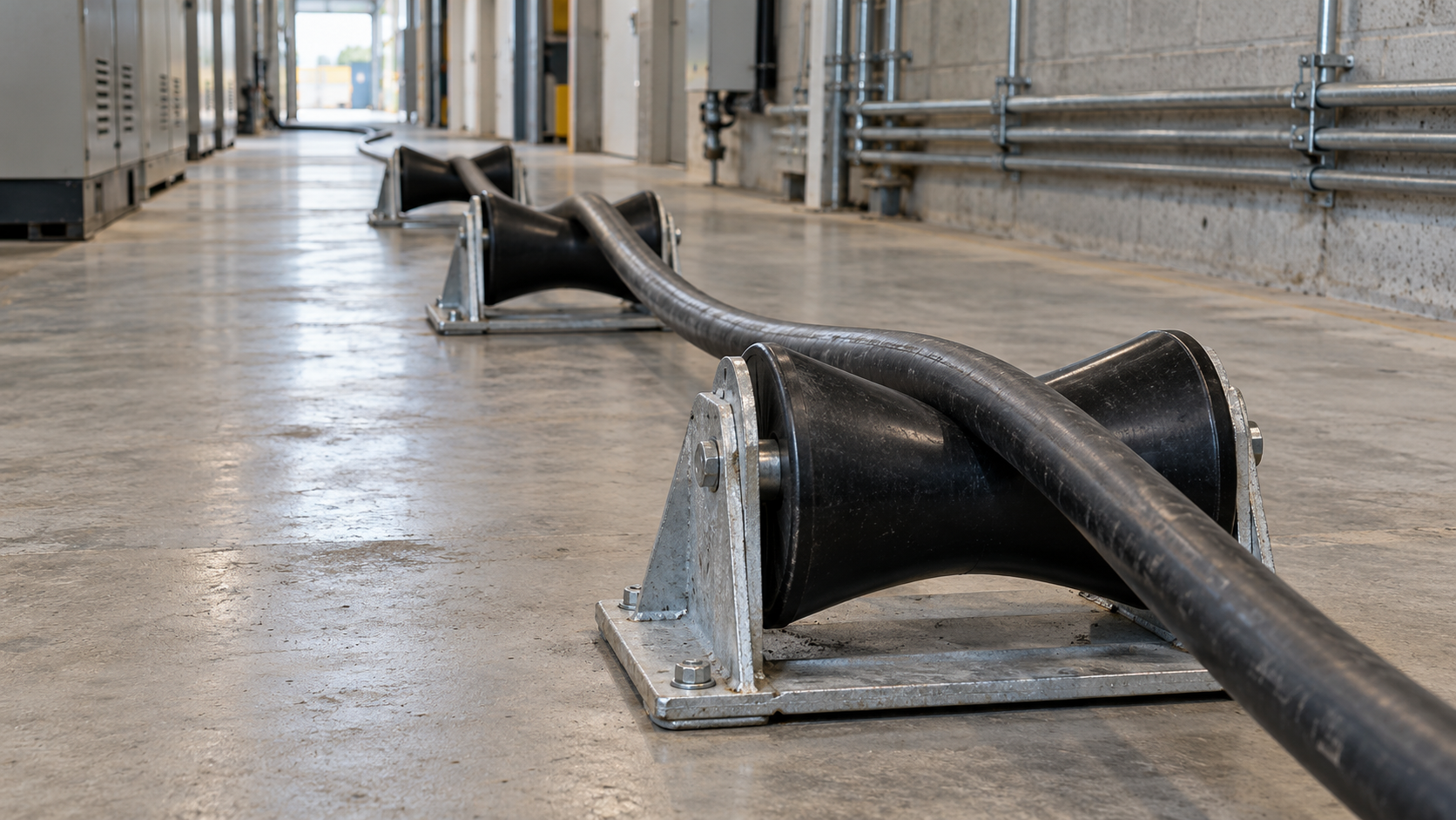
<p>我會區分起始接觸與運轉中的接觸，接著確認外護套、導管或支撐表面，以及相容的潤滑劑。滾輪應採用適用的模型並納入設備狀況；路線水平，不代表滾輪接觸可視為滑動表面。</p>
<figure>
<img alt="連續的黑色電纜沿工業走廊地面，架在三個低矮的線軸狀滾輪上" src="/images/blog/preliminary-cable-pulling-loads/preliminary-cable-pulling-loads-scene-01.png" width="1672" height="941" loading="lazy" decoding="async">
<figcaption>安裝在地面的滾輪沿路線支撐電纜，並界定電纜與支撐設備之間的接觸情形。</figcaption>
</figure>
<h2 id="how-much-load-does-a-vertical-cable-add">垂直電纜會增加多少負荷？</h2>
<p>對處於靜態平衡、自由懸垂且無支撐的一段電纜：</p>
<div class="article-math article-math-display" data-latex="W=\lambda L_vg"><span class="katex"><math xmlns="http://www.w3.org/1998/Math/MathML" display="block"><semantics><mrow><mi>W</mi><mo>=</mo><mi>λ</mi><msub><mi>L</mi><mi>v</mi></msub><mi>g</mi></mrow><annotation encoding="application/x-tex">W=\lambda L_vg</annotation></semantics></math></span></div>
<p><strong>懸吊重量</strong>是檢查點以下無支撐質量所受的重力。此處的 <span class="article-math article-math-inline" data-latex="L_v"><span class="katex"><math xmlns="http://www.w3.org/1998/Math/MathML"><semantics><mrow><msub><mi>L</mi><mi>v</mi></msub></mrow><annotation encoding="application/x-tex">L_v</annotation></semantics></math></span></span> 代表該長度，單位為公尺。我會先標出中間支撐點，再決定各點承受的長度。</p>
<p>再以同一條假設電纜的 6 m 懸垂段為例，電纜質量為 0.8 kg/m。該段重量為 47.07 N。若上方支撐點還承受一個 1.5 kg 的附掛件，該附掛件會增加 14.71 N，因此此靜態範例的總負荷為 61.78 N。附掛件只計算一次。若實際路線同時包含水平和垂直段，應分別計算兩段長度。</p>
<p>質量與重量必須使用不同單位。<a href="https://www.nist.gov/pml/special-publication-811/nist-guide-si-chapter-4-two-classes-si-units-and-si-prefixes">NIST 的 SI 單位表</a>將質量定義為公斤、力定義為牛頓。若電纜資料已提供 N/m 表示的單位長度重量，直接乘以長度即可。再次乘以重力加速度會高估該力。</p>
<p>對提升作業，應在適用的動態模型中納入加速度、支撐摩擦、附掛件及移動方向。若牽引作業已停止，應找出拆除牽引設備後承受重量的永久支撐件。</p>
<h2 id="what-changes-at-a-bend">彎道會帶來哪些變化？</h2>
<p><strong>彎道會同時改變牽引張力，以及將電纜壓向導向件的負荷。</strong>我會先計算局部出口張力，再將其代入適用的側壁負荷公式。導管內電纜的排列方式也很重要：單條電纜與多條各自獨立、共用一條導管的電纜，其接觸配置不同。</p>
<p>對採滑動接觸的單條電纜，常用的彎道初步近似式為：</p>
<div class="article-math article-math-display" data-latex="T_{\mathrm{out}}\approx T_{\mathrm{in}}e^{\mu_b\theta}"><span class="katex"><math xmlns="http://www.w3.org/1998/Math/MathML" display="block"><semantics><mrow><msub><mi>T</mi><mrow><mi mathvariant="normal">o</mi><mi mathvariant="normal">u</mi><mi mathvariant="normal">t</mi></mrow></msub><mo>≈</mo><msub><mi>T</mi><mrow><mi mathvariant="normal">i</mi><mi mathvariant="normal">n</mi></mrow></msub><msup><mi>e</mi><mrow><msub><mi>μ</mi><mi>b</mi></msub><mi>θ</mi></mrow></msup></mrow><annotation encoding="application/x-tex">T_{\mathrm{out}}\approx T_{\mathrm{in}}e^{\mu_b\theta}</annotation></semantics></math></span></div>
<p>此處 <span class="article-math article-math-inline" data-latex="\mu_b"><span class="katex"><math xmlns="http://www.w3.org/1998/Math/MathML"><semantics><mrow><msub><mi>μ</mi><mi>b</mi></msub></mrow><annotation encoding="application/x-tex">\mu_b</annotation></semantics></math></span></span> 為彎道的動摩擦係數，<span class="article-math article-math-inline" data-latex="\theta"><span class="katex"><math xmlns="http://www.w3.org/1998/Math/MathML"><semantics><mrow><mi>θ</mi></mrow><annotation encoding="application/x-tex">\theta</annotation></semantics></math></span></span> 為接觸角度，單位為弧度；<span class="article-math article-math-inline" data-latex="e"><span class="katex"><math xmlns="http://www.w3.org/1998/Math/MathML"><semantics><mrow><mi>e</mi></mrow><annotation encoding="application/x-tex">e</annotation></semantics></math></span></span> 為指數常數。這是 Southwire 近似式 E-15 的單電纜情況，其重量修正係數等於一。90°轉彎為 <span class="article-math article-math-inline" data-latex="\pi/2"><span class="katex"><math xmlns="http://www.w3.org/1998/Math/MathML"><semantics><mrow><mi>π</mi><mi mathvariant="normal">/</mi><mn>2</mn></mrow><annotation encoding="application/x-tex">\pi/2</annotation></semantics></math></span></span> 弧度。若將 90 當作弧度值輸入，結果會完全不同。</p>
<p>此近似式代表滑動接觸，並不涵蓋每一種旋轉滑輪或高剛度電纜彎道。Southwire 將自由轉動滑輪與電纜彎曲阻力分開處理。對實際路線，應採用適用的導管內電纜排列方式、彎道幾何及設備模型，並依該模型保留任何額外彎曲阻力或起動阻力。</p>
<h3 id="keep-sidewall-loading-in-nm">以 N/m 表示側壁負荷</h3>
<p>對單一單芯電纜，或置於同一共用外護套中的多條導體，簡化側壁指標為：</p>
<div class="article-math article-math-display" data-latex="q=\frac{T_{\mathrm{out}}}{R}"><span class="katex"><math xmlns="http://www.w3.org/1998/Math/MathML" display="block"><semantics><mrow><mi>q</mi><mo>=</mo><mfrac><msub><mi>T</mi><mrow><mi mathvariant="normal">o</mi><mi mathvariant="normal">u</mi><mi mathvariant="normal">t</mi></mrow></msub><mi>R</mi></mfrac></mrow><annotation encoding="application/x-tex">q=\frac{T_{\mathrm{out}}}{R}</annotation></semantics></math></span></div>
<p>使用離開彎道時的局部張力（N）和適用的彎曲半徑（m），得到的單位為 N/m。Southwire 將此形式列為 E-20，並為其他電纜排列方式提供不同公式。應依圖面保留模型採用的半徑慣例；滑輪外徑不一定就是所需的半徑。</p>
<p><strong>側壁負荷</strong>是沿彎道接觸面作用的單位長度力。雖然常稱為側壁壓力，這項指標並不是以帕斯卡表示的壓力。NIST 將帕斯卡定義為 N/m²。若要計算局部接觸應力，還需要接觸面積與負荷分佈。</p>
<p>以一個獨立範例來看，若有 <strong>400 N</strong> 張力離開彎道，半徑為 <strong>0.50 m</strong> 時，側壁指標為 <strong>800 N/m</strong>。同樣張力下，半徑為 <strong>0.80 m</strong> 時則為 <strong>500 N/m</strong>。較大的半徑會降低此指標，但所選幾何仍須符合電纜最小彎曲半徑，並能容納於路線之中。</p>
<h2 id="carry-tension-through-a-straightbendstraight-route">沿直線段—彎道—直線段路線傳遞張力</h2>
<p>此連續範例採用相同的假設電纜與重力值：單條電纜穩定滑過一段水平 20 m 直線、一個 90°彎道及另一段 10 m 直線。路線不含垂直區段。</p>
<p>假設第一段直線入口的張力為 25 N，兩段直線的摩擦係數皆為 0.30，彎道的摩擦係數為 0.20。側壁模型採用的彎曲半徑為 0.50 m。套用上文的簡化彎道近似式；此範例不納入起動瞬態、電纜剛度，以及該近似式以外的彎道重量修正。</p>
<table>
<thead>
<tr>
<th>位置或負荷項目</th>
<th>計算式</th>
<th>結果</th>
</tr>
</thead>
<tbody>
<tr>
<td>第一段直線的增加摩擦力</td>
<td>0.30 × 0.8 × 20 × 9.80665</td>
<td>47.07 N</td>
</tr>
<tr>
<td>進入彎道的張力</td>
<td>25 + 47.07192</td>
<td>72.07 N</td>
</tr>
<tr>
<td>彎道張力倍率</td>
<td>exp(0.20 × π/2)</td>
<td>1.3691</td>
</tr>
<tr>
<td>離開彎道的張力</td>
<td>72.07192 × 1.36910777</td>
<td>98.67 N</td>
</tr>
<tr>
<td>彎道局部側壁指標</td>
<td>98.67422572 / 0.50</td>
<td>197.35 N/m</td>
</tr>
<tr>
<td>第二段直線的增加摩擦力</td>
<td>0.30 × 0.8 × 10 × 9.80665</td>
<td>23.54 N</td>
</tr>
<tr>
<td>最後出口處的張力</td>
<td>98.67422572 + 23.53596</td>
<td>122.21 N</td>
</tr>
</tbody>
</table>
<p>將 <strong>122.21 N</strong> 用於最後出口處，並將 <strong>98.67 N</strong> 用於彎道出口處。把最終數值代入前面的彎道檢查，會混淆路線位置。我會在逐步計算時保留完整精度，並將顯示結果四捨五入。</p>
<p>依我對此範例的分析，將彎曲半徑從 0.50 m 增至 0.80 m，會使側壁指標從 197.35 降至 123.34 N/m；在相同張力下，降幅為 37.5%。由於半徑不在指數近似式中，估算張力維持不變。實際路線設計也須檢查電纜彎曲半徑與剛度。</p>
<p>牽引方向改變時，應重新計算。此時直線段與彎道的先後順序會不同，進入各彎道的張力也可能改變。若路線有高程變化，重量項對牽引負荷的貢獻方向也會隨之改變。應比較重新計算的局部負荷與設備可及性，而不只是反轉已完成計算表上的箭頭。</p>
<h2 id="which-limits-control-cable-pulling-loads">哪些限值會控制電纜牽引負荷？</h2>
<p><strong>將每項計算負荷與該電纜、附件、位置及工況所適用的限值比較。</strong>最後出口處的張力較低，並不能判定緊彎處的側壁負荷。同樣地，電纜張力限值較寬裕，也不會提高牽引眼或夾具的額定承載能力。</p>
<table>
<thead>
<tr>
<th>檢查項目</th>
<th>比較對象</th>
<th>比較未通過時</th>
</tr>
</thead>
<tbody>
<tr>
<td>電纜張力</td>
<td>指定構造及牽引方法的電纜限值</td>
<td>降低路線需求，或修訂已核准的牽引配置</td>
</tr>
<tr>
<td>牽引附件</td>
<td>額定承載能力及安裝條件</td>
<td>選擇合適的附件，並重新檢查整個系統</td>
</tr>
<tr>
<td>各彎道</td>
<td>適用的側壁負荷限值及最小彎曲半徑</td>
<td>增大半徑、改變路線，或降低進入彎道的張力</td>
</tr>
<tr>
<td>導向件與支撐件</td>
<td>軸向／橫向負荷能力及結構安裝方式</td>
<td>修訂組件、間距或安裝設計</td>
</tr>
<tr>
<td>最後的電纜入口</td>
<td>電纜對正、支撐及電纜密封接頭的保持工況</td>
<td>在完成電纜密封接頭端接前，修正電纜進線路徑與支撐配置</td>
</tr>
</tbody>
</table>
<p>Southwire 的指南將牽引設備限值、電纜張力、側壁負荷及路線幾何分別說明。允許數值應依目前適用的電纜與附件說明，並與各位置的計算需求比較。</p>
<p>負責的安裝工程師也會處理電纜盤阻力、起動效應、牽引期間的變化，以及障礙或卡阻風險。安裝計畫應納入負荷監測與停止準則。</p>
<h2 id="where-do-cleats-and-the-cable-gland-fit">電纜固定夾與電纜密封接頭應如何配合？</h2>
<p>我會將路線負荷分配給專為承受該負荷而設計的組件。<a href="https://webstore.iec.ch/en/publication/64504">IEC 61914:2021</a> 涵蓋電纜固定夾與中間固定件，包括其宣告的工況與指定安裝表面。<a href="https://webstore.iec.ch/en/publication/7034">IEC 62444:2010</a> 涵蓋完整的電纜密封接頭。這些組件的功能各自不同，且具有各自的安裝條件。</p>
<p>電纜密封接頭的電纜保持性能，並不表示它可作為牽引附件或不受限制的垂直支撐件。先確認無支撐長度、附掛負荷及支撐反力，再依該工況匹配組件。《<a href="/zh-hant/blog/a-technical-guide-to-cable-cleats-and-their-relationship-with-cable-glands/">電纜夾與電纜密封接頭指南</a>》說明兩者在外殼入口處的關係。</p>
<p>在最後一個彎道，我會檢查所需的直線進線段、外殼伸出量及支撐位置。避免電纜側向壓迫電纜密封接頭的入口端。《<a href="/zh-hant/blog/how-does-cable-bending-radius-affect-your-cable-gland-selection/">彎曲半徑選用指南</a>》說明相關幾何，《<a href="/zh-hant/blog/a-guide-to-strain-relief-in-cable-glands-preventing-cable-damage-and-disconnection/">應力釋放指南</a>》則說明安裝後的使用負荷。</p>
<h2 id="keep-a-usable-route-calculation-sheet">保留可用的路線計算表</h2>
<table>
<thead>
<tr>
<th>記錄項目</th>
<th>填入計算表的內容</th>
</tr>
</thead>
<tbody>
<tr>
<td>電纜</td>
<td>標示、單位長度質量、直徑及牽引方法</td>
</tr>
<tr>
<td>區段</td>
<td>方向、長度、角度、半徑及支撐條件</td>
</tr>
<tr>
<td>力平衡</td>
<td>進入張力、增加的負荷及出口張力</td>
</tr>
<tr>
<td>輸入值與限值</td>
<td>摩擦依據、電纜限值及附件限值</td>
</tr>
<tr>
<td>未解決的條件</td>
<td>電纜盤阻力、起動效應或設備狀況</td>
</tr>
</tbody>
</table>
<p>輸入值變動時，我會重新計算受影響的下游區段。未確認的負荷應明確列出，不要將其隱藏在通用係數中。</p>
<h2 id="conclusion">結論</h2>
<p>我會沿路線追蹤受力情況，以計算電纜牽引負荷。水平區段會增加摩擦力，無支撐的上升段會增加重量，而彎道會改變張力並產生局部側壁負荷。將出口張力帶入下一段，可以連結這些負荷貢獻，同時避免混淆其單位或作用位置。</p>
<p>選擇牽引配置前，應將局部結果與電纜、附件、彎道及支撐的限值比較。在外殼處，應提供預期的電纜支撐及進線路徑幾何配置，使電纜密封接頭發揮指定的引入與保持功能。</p>
<h2 id="faqs-about-preliminary-cable-pulling-loads">電纜牽引負荷常見問題</h2>
<h3 id="does-the-horizontal-calculator-give-the-total-pulling-tension">水平計算器會給出總牽引張力嗎？</h3>
<p>此模型會算出水平滑動區段增加的摩擦力。將進入張力另行加上，再依適用模型計算後續直線段、彎道或垂直區段。我會把各區段的結果列為路線表中的一項，而不把它當成每條路線的最終數值。</p>
<h3 id="can-i-enter-cable-weight-in-kilograms-as-a-force">可以把電纜重量以公斤輸入，當作力嗎？</h3>
<p>公斤表示質量。將質量乘以重力加速度，即可換算為牛頓表示的力。若資料表已提供單位長度重量 N/m，直接乘以長度，不要再乘一次重力加速度。整個計算中應清楚區分 kg/m 與 N/m。</p>
<h3 id="why-is-sidewall-pressure-expressed-in-nm">為什麼側壁壓力以 N/m 表示？</h3>
<p>簡化的單條電纜彎道指標，是以該彎道出口處的局部張力除以適用的彎曲半徑。其單位為單位長度的力，即使常稱為側壁壓力也是如此。若要以 N/m² 計算接觸應力，還需要接觸面積和負荷分佈資料。</p>
<h3 id="can-a-cable-gland-carry-the-weight-of-a-vertical-cable-run">電纜密封接頭能承受垂直電纜路線的重量嗎？</h3>
<p>只有在確切的電纜密封接頭、電纜與安裝配置均依該負荷明確規定時，才可讓它承受此工況。我會先找出無支撐長度和其他支撐，再依該負荷路徑選擇組件。僅有電纜保持能力，並不表示電纜密封接頭可作為牽引附件。</p>
<h3 id="will-a-larger-bend-always-reduce-the-final-pulling-tension">較大的彎曲半徑是否一定會降低最終牽引張力？</h3>
<p>在相同張力下，較大的半徑會降低簡化側壁指標。指數形式彎道近似式中的張力取決於進入張力、摩擦與角度，因此只改變半徑並不會改變該估算值。仍須檢查實際電纜剛度、彎道幾何和設備模型。</p>
<h3 id="sources-and-technical-references">來源與技術參考資料</h3>
<ul>
<li><a href="https://www.southwire.com/medias/sys_master/installation-manuals/installation-manuals/h29/hb6/8887676141598/PowerCableInstallGuidepdf.pdf">Southwire —《電力電纜安裝指南》（2005），牽引張力與側壁負荷模型</a>；取用日期：2026-10-28。</li>
<li><a href="https://www.nist.gov/pml/special-publication-811/nist-guide-si-chapter-4-two-classes-si-units-and-si-prefixes">NIST —《SI 單位指南》第 4 章：質量、力與壓力單位</a>；取用日期：2026-10-28。</li>
<li><a href="https://webstore.iec.ch/en/publication/64504">IEC 61914:2021 — 電氣裝置用電纜夾</a>；取用日期：2026-10-28。</li>
<li><a href="https://webstore.iec.ch/en/publication/7034">IEC 62444:2010 — 完整電纜密封接頭的構造與性能範圍</a>；取用日期：2026-10-28。</li>
</ul>
