# 轉移阻抗試驗如何量化 EMC 電纜密封接頭的屏蔽效能？

> Source: https://chinacableglands.com/zh-hant/blog/how-does-transfer-impedance-testing-quantify-emc-cable-gland-shielding-effectiveness/
> Language: zh-Hant
> Publisher: 倍拓電纜接頭
> Author: Victor Huang
> Published: 2026-03-01
> Updated: 2026-08-08

了解轉移阻抗如何將感應電壓與屏蔽電流轉換為依頻率表示的 EMC 電纜密封接頭結果，以及如何比較試驗報告。

<p><strong>轉移阻抗試驗會測量在已知電流流經外層屏蔽時，電纜引入試件受保護側的耦合電壓。</strong>對電磁相容性（EMC）電纜密封接頭而言，我會將其視為隨頻率變化的結果。只有當試件、治具、電纜、單位、頻率及計算方法相當時，較低的轉移阻抗才表示量測到的磁耦合較少。</p>
<blockquote>
<p><strong>重點摘要</strong></p>
<ul>
<li><strong>轉移阻抗</strong>是耦合電壓與屏蔽電流的比值，並以頻率為基準呈現。</li>
<li>以歐姆／公尺表示的電纜結果，不能與以歐姆表示的集中式連接器、穿隔件或電纜密封接頭結果互換。</li>
<li>IEC 62153 涵蓋電纜屏蔽層、連接器、組件、穿隔件、墊片及其他元件的不同方法。</li>
<li>並不存在適用於所有電纜密封接頭與應用的通用「優良」mΩ 或 mΩ/m 門檻。</li>
<li>有用的報告會先界定完整試件與試驗方法，再提供曲線或限值。</li>
</ul>
</blockquote>
<h2 id="what-does-transfer-impedance-actually-quantify">轉移阻抗實際量化什麼？</h2>
<p><strong>轉移阻抗試驗</strong>是在受控條件下量測屏蔽路徑的電磁耦合。試驗施加已知的屏蔽電流，並量測受保護側的感應電壓。我會讓結果始終對應到其試件與試驗條件。單靠這項結果，不能認證整個外殼、機器或安裝。</p>
<p>例如，若均勻電纜屏蔽層的結果按長度正規化，會使用下列簡化關係：</p>
<div class="article-math article-math-display" data-latex="Z&#39;_T(f) = \frac{U_2(f)}{I_1(f)L}"><span class="katex"><math xmlns="http://www.w3.org/1998/Math/MathML" display="block"><semantics><mrow><msubsup><mi>Z</mi><mi>T</mi><mo mathvariant="normal" lspace="0em" rspace="0em">′</mo></msubsup><mo stretchy="false">(</mo><mi>f</mi><mo stretchy="false">)</mo><mo>=</mo><mfrac><mrow><msub><mi>U</mi><mn>2</mn></msub><mo stretchy="false">(</mo><mi>f</mi><mo stretchy="false">)</mo></mrow><mrow><msub><mi>I</mi><mn>1</mn></msub><mo stretchy="false">(</mo><mi>f</mi><mo stretchy="false">)</mo><mi>L</mi></mrow></mfrac></mrow><annotation encoding="application/x-tex">Z&#x27;_T(f) = \frac{U_2(f)}{I_1(f)L}</annotation></semantics></math></span></div>
<p>其中，<span class="article-math article-math-inline" data-latex="Z&#39;_T(f)"><span class="katex"><math xmlns="http://www.w3.org/1998/Math/MathML"><semantics><mrow><msubsup><mi>Z</mi><mi>T</mi><mo mathvariant="normal" lspace="0em" rspace="0em">′</mo></msubsup><mo stretchy="false">(</mo><mi>f</mi><mo stretchy="false">)</mo></mrow><annotation encoding="application/x-tex">Z&#x27;_T(f)</annotation></semantics></math></span></span>表示以每公尺為基準、頻率<span class="article-math article-math-inline" data-latex="f"><span class="katex"><math xmlns="http://www.w3.org/1998/Math/MathML"><semantics><mrow><mi>f</mi></mrow><annotation encoding="application/x-tex">f</annotation></semantics></math></span></span>時的表面轉移阻抗，單位為歐姆／公尺；<span class="article-math article-math-inline" data-latex="U_2(f)"><span class="katex"><math xmlns="http://www.w3.org/1998/Math/MathML"><semantics><mrow><msub><mi>U</mi><mn>2</mn></msub><mo stretchy="false">(</mo><mi>f</mi><mo stretchy="false">)</mo></mrow><annotation encoding="application/x-tex">U_2(f)</annotation></semantics></math></span></span>表示耦合的縱向電壓，單位為伏特；<span class="article-math article-math-inline" data-latex="I_1(f)"><span class="katex"><math xmlns="http://www.w3.org/1998/Math/MathML"><semantics><mrow><msub><mi>I</mi><mn>1</mn></msub><mo stretchy="false">(</mo><mi>f</mi><mo stretchy="false">)</mo></mrow><annotation encoding="application/x-tex">I_1(f)</annotation></semantics></math></span></span>表示施加的屏蔽電流，單位為安培；而<span class="article-math article-math-inline" data-latex="L"><span class="katex"><math xmlns="http://www.w3.org/1998/Math/MathML"><semantics><mrow><mi>L</mi></mrow><annotation encoding="application/x-tex">L</annotation></semantics></math></span></span>表示受評估的屏蔽長度，單位為公尺。撇號用來區分以長度正規化的量與集中式元件結果。</p>
<p>對於局部連接器、穿隔件或電纜引入試件，我會確認報告是否採用集中式轉移阻抗。「集中式」表示數值適用於明確界定的元件，而不是按單位電纜長度計算：</p>
<div class="article-math article-math-display" data-latex="Z_T(f) = \frac{U_2(f)}{I_1(f)}"><span class="katex"><math xmlns="http://www.w3.org/1998/Math/MathML" display="block"><semantics><mrow><msub><mi>Z</mi><mi>T</mi></msub><mo stretchy="false">(</mo><mi>f</mi><mo stretchy="false">)</mo><mo>=</mo><mfrac><mrow><msub><mi>U</mi><mn>2</mn></msub><mo stretchy="false">(</mo><mi>f</mi><mo stretchy="false">)</mo></mrow><mrow><msub><mi>I</mi><mn>1</mn></msub><mo stretchy="false">(</mo><mi>f</mi><mo stretchy="false">)</mo></mrow></mfrac></mrow><annotation encoding="application/x-tex">Z_T(f) = \frac{U_2(f)}{I_1(f)}</annotation></semantics></math></span></div>
<p>此結果的單位為歐姆。我會依據確切方法及報告採用方程式、修正方式與正規化方式。<a href="https://webstore.iec.ch/en/publication/94796">IEC 62153-4-3:2013+AMD1:2024 CSV</a>規定在電纜屏蔽層上施加明確的電流與電壓，並量測感應電壓，以取得表面轉移阻抗。其範圍只量測磁性分量。正規化是指將結果表示為相對於指定基準的數值，例如長度。</p>
<table>
<thead>
<tr>
<th>報告的量</th>
<th>常用單位</th>
<th>讀者必須確認的事項</th>
</tr>
</thead>
<tbody>
<tr>
<td>電纜表面轉移阻抗</td>
<td>Ω/m or mΩ/m</td>
<td>受評估長度、電纜結構、頻率及方法</td>
</tr>
<tr>
<td>集中式元件轉移阻抗</td>
<td>Ω or mΩ</td>
<td>裝置邊界、治具、轉接頭、參考平面及頻率</td>
</tr>
<tr>
<td>屏蔽衰減或耦合衰減</td>
<td>dB</td>
<td>試驗方法、頻率範圍、阻抗及試件定義</td>
</tr>
<tr>
<td>直流導通或電阻</td>
<td>Ω or mΩ</td>
<td>電流路徑與接觸狀態；不能取代射頻曲線</td>
</tr>
</tbody>
</table>
<p>《<a href="/zh-hant/resource-center/cable-entry-glossary/">電纜引入詞彙表》</a>區分屏蔽、等電位連接、導通及 EMC 用語。我會將直流（DC）電阻與射頻（RF）響應分開看待。幾何形狀改變後，即使直流電阻低，高頻表現仍可能不佳。</p>
<h2 id="choosing-the-iec-method-for-the-device-under-test">如何為受測裝置選擇 IEC 方法</h2>
<p>我會依實際試件選擇方法。所謂「EMC 電纜密封接頭」可能在電纜組件、屏蔽連接、穿隔件或元件治具中受測。每種配置都有自己的試驗架設與報告規則。</p>
<table>
<thead>
<tr>
<th>IEC 出版文件</th>
<th>公開範圍摘要</th>
<th>與電纜密封接頭評估的關聯</th>
</tr>
</thead>
<tbody>
<tr>
<td><a href="https://webstore.iec.ch/en/publication/94796">IEC 62153-4-3:2013+AMD1:2024 CSV</a></td>
<td>使用三軸法量測電纜屏蔽層的表面轉移阻抗</td>
<td>建立電纜屏蔽量測概念；不會自動成為接頭試驗方法</td>
</tr>
<tr>
<td><a href="https://webstore.iec.ch/en/publication/110359">IEC 62153-4-7:2021+AMD1:2025 CSV</a></td>
<td>使用管中管三軸法量測已配接屏蔽連接器與電纜組件的轉移阻抗，以及屏蔽或耦合衰減</td>
<td>試件若界定為屏蔽連接或組件，即與此相關</td>
</tr>
<tr>
<td><a href="https://webstore.iec.ch/en/publication/67390">IEC 62153-4-10:2015+AMD1:2020 CSV</a></td>
<td>使用雙同軸法量測穿隔件與電磁墊片的轉移阻抗或屏蔽衰減</td>
<td>接頭配置若視為外殼穿隔件，即與此相關</td>
</tr>
<tr>
<td><a href="https://webstore.iec.ch/en/publication/94574">IEC 62153-4-15:2021+AMD1:2024 CSV</a></td>
<td>適用於連接器、電纜組件及元件的三軸試驗單元程序</td>
<td>適用於符合其明確範圍及轉接方法的元件配置</td>
</tr>
</tbody>
</table>
<p>我會確認確切的 IEC 分冊與版次。公開頁面顯示，IEC 62153-4-7 合併版包含 2025 年修正案，IEC 62153-4-3 合併版包含 2024 年修正案。「依 IEC 62153 試驗」並未說明實際採用哪種方法。還要記錄修正案狀態、適用條款或架設方式，以及客戶驗收規格。</p>
<p><a href="https://webstore.iec.ch/en/publication/67030">IEC TS 62153-4-1:2014+AMD1:2020 CSV</a>探討不同屏蔽品質方法及其正確判讀方式。我會先釐清方法，再採用性能標示。</p>
<h2 id="how-does-a-triaxial-test-turn-coupling-into-a-number">三軸試驗如何將耦合轉換為數值？</h2>
<p>三軸試驗在屏蔽試件周圍形成兩個受控電路。一個沿外層屏蔽驅動電流；另一個偵測耦合電壓。實驗室依校正及治具規則計算頻率響應。我會檢查參考平面，也就是量測所依據的明確界線。</p>
<p>我會檢視下列六個量測階段：</p>
<ol>
<li><strong>定義試件。</strong>記錄電纜與屏蔽層、預備長度、接頭或連接器、壁面或轉接頭、配件及組裝狀態。</li>
<li><strong>註明方法。</strong>記錄 IEC 分冊與版次、偏差及任何客戶程序。</li>
<li><strong>控制電流路徑。</strong>三軸或雙同軸治具會界定外部電路與電磁邊界。</li>
<li><strong>量測。</strong>使用經校正的儀器，在指定頻帶內量測，並採用規定的終端與參考平面。</li>
<li><strong>計算。</strong>套用方法中的方程式、修正值、相關長度正規化及不確定度。</li>
<li><strong>比較。</strong>使用適用於相同量、單位、試件邊界及頻率範圍的判準。</li>
</ol>
<p>例如，假設某局部試件在一個頻率下產生耦合電壓<span class="article-math article-math-inline" data-latex="U_2 = 2\,\mu\text{V}"><span class="katex"><math xmlns="http://www.w3.org/1998/Math/MathML"><semantics><mrow><msub><mi>U</mi><mn>2</mn></msub><mo>=</mo><mn>2</mn><mtext> </mtext><mi>μ</mi><mtext>V</mtext></mrow><annotation encoding="application/x-tex">U_2 = 2\,\mu\text{V}</annotation></semantics></math></span></span>，而量得的屏蔽電流為<span class="article-math article-math-inline" data-latex="I_1 = 0.5\,\text{A}"><span class="katex"><math xmlns="http://www.w3.org/1998/Math/MathML"><semantics><mrow><msub><mi>I</mi><mn>1</mn></msub><mo>=</mo><mn>0.5</mn><mtext> </mtext><mtext>A</mtext></mrow><annotation encoding="application/x-tex">I_1 = 0.5\,\text{A}</annotation></semantics></math></span></span>。其簡化的集中式結果為：</p>
<div class="article-math article-math-display" data-latex="Z_T = \frac{2\,\mu\text{V}}{0.5\,\text{A}} = 4\,\mu\Omega"><span class="katex"><math xmlns="http://www.w3.org/1998/Math/MathML" display="block"><semantics><mrow><msub><mi>Z</mi><mi>T</mi></msub><mo>=</mo><mfrac><mrow><mn>2</mn><mtext> </mtext><mi>μ</mi><mtext>V</mtext></mrow><mrow><mn>0.5</mn><mtext> </mtext><mtext>A</mtext></mrow></mfrac><mo>=</mo><mn>4</mn><mtext> </mtext><mi>μ</mi><mi mathvariant="normal">Ω</mi></mrow><annotation encoding="application/x-tex">Z_T = \frac{2\,\mu\text{V}}{0.5\,\text{A}} = 4\,\mu\Omega</annotation></semantics></math></span></div>
<p>我只用這項算術說明單一頻率點。它不是驗收限值，也未納入不確定度及治具修正。完整試驗須提供曲線、電流量測方法，以及明確的集中式或長度正規化結果。</p>
<figure>
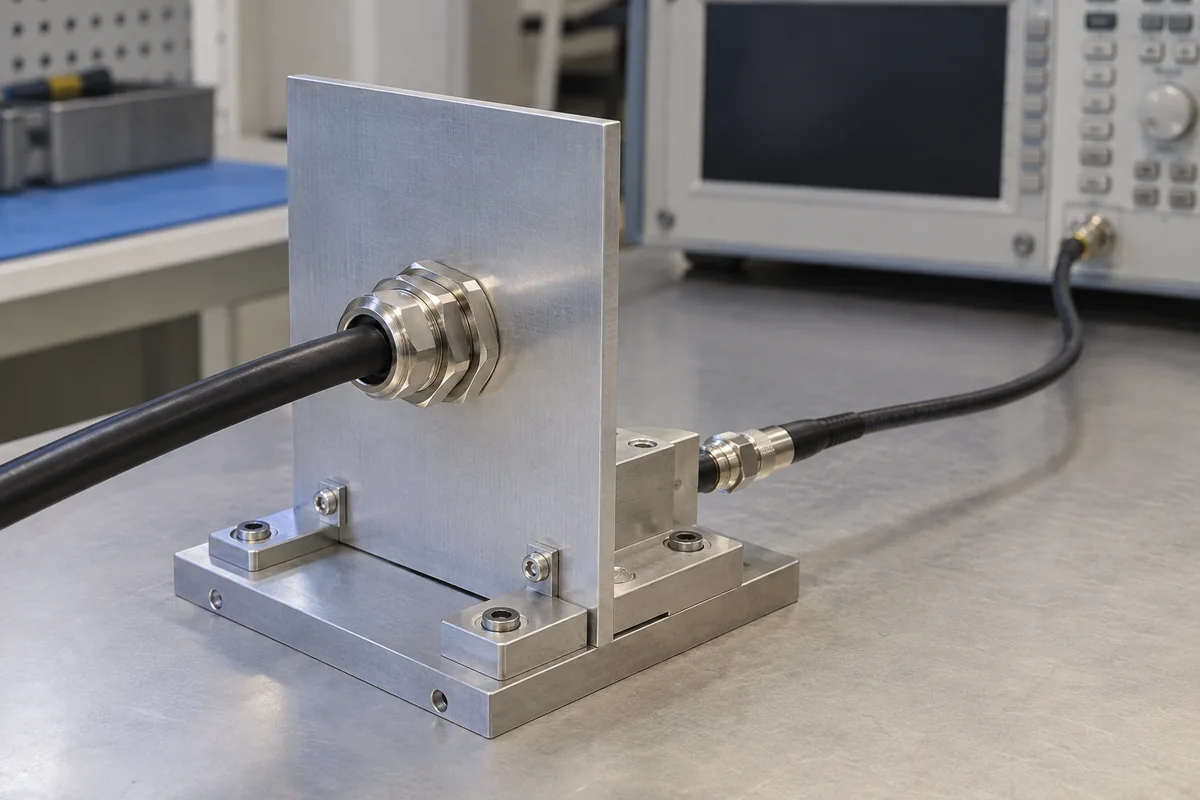
<img alt="射頻試驗台示意圖：一條電纜穿入固定面板上的金屬接頭，另有一條獨立導線通往儀器" src="/images/blog/how-does-transfer-impedance-testing-quantify-emc-cable-gland-shielding-effectiveness/single-specimen-rf-bench.webp" srcset="/images/blog/how-does-transfer-impedance-testing-quantify-emc-cable-gland-shielding-effectiveness/single-specimen-rf-bench-600.webp 600w, /images/blog/how-does-transfer-impedance-testing-quantify-emc-cable-gland-shielding-effectiveness/single-specimen-rf-bench.webp 1200w" sizes="(max-width: 640px) 100vw, 760px" width="1200" height="800" loading="lazy" decoding="async">
<figcaption>單一試件治具與射頻儀器並置的示意。記錄實際方法與參考平面。</figcaption>
</figure>
<h2 id="what-makes-two-transfer-impedance-results-comparable">哪些條件相同，兩個轉移阻抗結果才可比較？</h2>
<p>只有當量測量與試驗條件符合預定判斷用途時，我才會比較結果。採用不同方法、單位、治具、電纜或頻率所得的較小數值，不能證明接頭更好。若使用去嵌入，須確認如何移除已界定的治具貢獻。</p>
<p>我會先比較下列欄位：</p>
<table>
<thead>
<tr>
<th>比較欄位</th>
<th>影響結果意義的原因</th>
</tr>
</thead>
<tbody>
<tr>
<td>受測裝置</td>
<td>裸電纜、已配接連接器、電纜組件、穿隔件及裝在面板中的接頭，是不同的電氣試件。</td>
</tr>
<tr>
<td>單位與正規化</td>
<td>電纜的 mΩ/m 不能直接與局部元件的 mΩ 排序比較。</td>
</tr>
<tr>
<td>頻率點與頻寬</td>
<td>轉移阻抗是一條曲線；單一低頻數值不能代表完整響應。</td>
</tr>
<tr>
<td>電纜屏蔽層</td>
<td>編織材料、覆蓋率、箔層、排流線及組合屏蔽會改變進入路徑。</td>
</tr>
<tr>
<td>屏蔽層預備</td>
<td>裸露長度、折回編織層、接觸直徑及損傷的股線會改變介面。</td>
</tr>
<tr>
<td>接頭與外殼介面</td>
<td>接觸幾何、轉接頭、塗層、壁面材料及等電位連接會決定通過引入口的路徑。</td>
</tr>
<tr>
<td>組裝狀態</td>
<td>鎖緊、方向、配件及重新組裝都可能改變接觸狀態。</td>
</tr>
<tr>
<td>治具與校正</td>
<td>參考平面、轉接頭、終端、動態範圍及去嵌入都會影響報告曲線。</td>
</tr>
<tr>
<td>不確定度與重複性</td>
<td>若差異落在量測不確定度或樣品變異範圍內，就沒有實質比較意義。</td>
</tr>
</tbody>
</table>
<p>若進行匹配的 A/B 比較，我會參考<a href="/zh-hant/blog/transfer-impedance-testing-quantifying-the-shielding-effectiveness-of-emc-cable-glands/">轉移阻抗比較試驗指南</a>，了解治具能力、重裝重複試驗及不確定度。開始排序前，先確認量、單位及方法相同。</p>
<p><a href="https://webstore.iec.ch/en/publication/110359">IEC 62153-4-7:2021+AMD1:2025 CSV</a>的範圍包含電纜與連接器間的連接。因此，我會將端接與配接配置納入試件紀錄。僅有連接器本體識別資料並不足夠。</p>
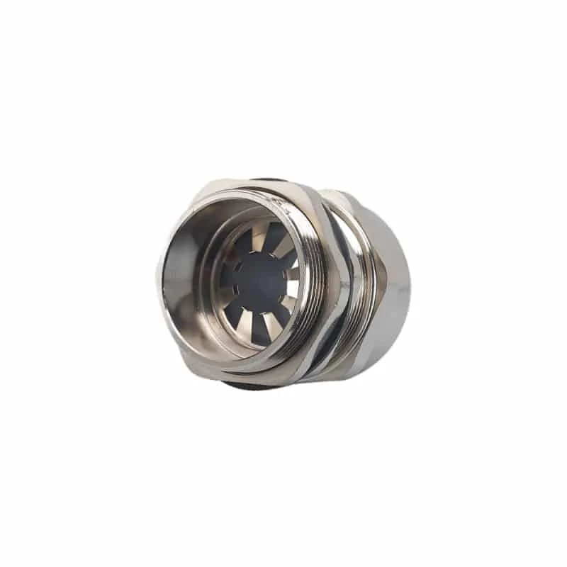
<img alt="帶有徑向彈簧指的金屬 EMC 電纜密封接頭，用於接觸電纜屏蔽層" src="/images/blog/how-does-transfer-impedance-testing-quantify-emc-cable-gland-shielding-effectiveness/wp-emc-gland-spring-contact.webp" width="800" height="800" loading="lazy" decoding="async">
<p>徑向彈簧指在電纜開口周圍接觸已預備的屏蔽層。我仍會記錄屏蔽結構、接觸直徑、預備長度、接頭變體、面板轉接頭及方法。圖片無法提供這些識別資訊。</p>
<h2 id="interpreting-lower-transfer-impedance-values">如何解讀較低的轉移阻抗數值</h2>
<p>我會將完整曲線與相同量、單位、頻帶、電纜、治具及組件的專案限值比較。不存在通用的「良好」接頭數值。只有在相同量測邊界內，較低數值才表示量得的磁耦合較少。</p>
<p>以下三項檢查可避免大多數判讀錯誤：</p>
<ul>
<li><strong>單位正確嗎？</strong>不要將電纜的 mΩ/m 門檻套用於以 mΩ 表示的集中式元件結果。</li>
<li><strong>頻率範圍正確嗎？</strong>通過單一頻率點，不能證明其上下頻率的性能。</li>
<li><strong>試件正確嗎？</strong>接頭本體的結果不會自動涵蓋電纜屏蔽層預備、外殼塗層、轉接頭或最終等電位連接路徑。</li>
</ul>
<figure class="blog-chart" style="container-type: inline-size;">
<svg xmlns="http&#58;//www.w3.org/2000/svg" viewBox="0 0 520 1030" role="img" aria-labelledby="ti-measure-title ti-measure-desc" style="font-family:var(--font-body); width: 100% !important; max-width: 100% !important; height: auto !important;" id="cg-typography-2b85801958276b66">
<style>
#cg-typography-2b85801958276b66 { --svg-body-screen: 17px; }
@media (max-width: 760px) { #cg-typography-2b85801958276b66 { --svg-body-screen: 16px; } }
</style>
<title id="ti-measure-title">轉移阻抗物理量與量測邊界</title>
<desc id="ti-measure-desc">單一試件的概念性電纜引入圖，分別標示記錄的屏蔽電流與耦合電壓。兩張公式卡區分單位為歐姆的局部元件結果，以及單位為歐姆／公尺的電纜屏蔽結果。小型曲線圖強調需宣告頻帶。</desc>
<defs><marker id="ti-measure-arrow" markerWidth="10" markerHeight="10" refX="9" refY="5" orient="auto"><path d="M0 0L10 5L0 10Z" fill="var(--color-primary)"/></marker></defs>
<text x="260" y="43" text-anchor="middle" fill="var(--color-carbon)" font-size="27" font-weight="700" style="font-size: calc(22px * 520px / 100cqw) !important;">試驗量測的內容</text>
<text x="260" y="77" text-anchor="middle" fill="var(--color-graphite)" font-size="22" style="font-size: calc(var(--svg-body-screen) * 520px / 100cqw) !important;">一個試件，兩個量測量</text>
<rect x="24" y="110" width="472" height="344" rx="18" fill="var(--surface-card)" stroke="var(--color-primary)" stroke-width="3"/>
<text x="48" y="153" fill="var(--color-carbon)" font-size="24" font-weight="700" style="font-size: calc(18px * 520px / 100cqw) !important;">宣告受測物件</text>
<text x="48" y="185" fill="var(--color-graphite)" font-size="21" style="font-size: calc(16px * 520px / 100cqw) !important;">電纜 · 屏蔽層 · 接頭 · 面板</text>
<rect x="357" y="216" width="56" height="140" rx="5" fill="var(--color-ash)" stroke="var(--color-graphite)" stroke-width="3"/>
<rect x="70" y="262" width="385" height="45" rx="22" fill="#334155"/>
<path d="M82 284H373" fill="none" stroke="var(--color-primary)" stroke-width="5" stroke-dasharray="12 7"/>
<rect x="321" y="251" width="108" height="67" rx="18" fill="var(--surface-card)" stroke="var(--color-primary)" stroke-width="5"/>
<path d="M103 238H297" fill="none" stroke="var(--color-primary)" stroke-width="4" marker-end="url(#ti-measure-arrow)"/>
<text x="96" y="214.407" fill="var(--color-carbon)" font-size="22" font-weight="700" style="font-size: calc(16px * 520px / 100cqw) !important;">屏蔽路徑上的 I1</text>
<text x="48" y="377" fill="var(--color-carbon)" font-size="22" font-weight="700" style="font-size: calc(16px * 520px / 100cqw) !important;">U2：內側的耦合電壓</text>
<text x="48" y="411" fill="var(--color-graphite)" font-size="21" style="font-size: calc(var(--svg-body-screen) * 520px / 100cqw) !important;">參考平面依所採方法界定。</text>
<path d="M260 455V493" fill="none" stroke="var(--color-primary)" stroke-width="4" marker-end="url(#ti-measure-arrow)"/>
<rect x="24" y="506" width="472" height="255" rx="18" fill="var(--surface-card)" stroke="var(--color-primary)" stroke-width="3"/>
<text x="48" y="548" fill="var(--color-carbon)" font-size="24" font-weight="700" style="font-size: calc(18px * 520px / 100cqw) !important;">選擇報告的量</text>
<text x="48" y="586" fill="var(--color-carbon)" font-size="21" font-weight="700" style="font-size: calc(18px * 520px / 100cqw) !important;">局部引入口或元件</text>
<text x="48" y="622" fill="var(--color-carbon)" font-size="25" font-weight="700" style="font-size: calc(18px * 520px / 100cqw) !important;">ZT(f) = U2(f) / I1(f)</text>
<text x="48" y="650" fill="var(--color-graphite)" font-size="21" style="font-size: calc(16px * 520px / 100cqw) !important;">集中式結果 · Ω</text>
<path d="M48 672H472" fill="none" stroke="var(--color-cloud)" stroke-width="2"/>
<text x="48" y="706" fill="var(--color-carbon)" font-size="21" font-weight="700" style="font-size: calc(16px * 520px / 100cqw) !important;">均勻電纜屏蔽層 · Ω/m</text>
<text x="48" y="738" fill="var(--color-carbon)" font-size="24" font-weight="700" style="font-size: calc(16px * 520px / 100cqw) !important;">Z'T(f) = U2(f) / [I1(f) L]</text>
<path d="M260 762V800" fill="none" stroke="var(--color-primary)" stroke-width="4" marker-end="url(#ti-measure-arrow)"/>
<rect x="24" y="813" width="472" height="153" rx="18" fill="var(--surface-card)" stroke="var(--color-primary)" stroke-width="3"/>
<text x="48" y="852" fill="var(--color-carbon)" font-size="24" font-weight="700" style="font-size: calc(18px * 520px / 100cqw) !important;">讀取跨頻率曲線</text>
<path d="M73 933V877M73 933H464" fill="none" stroke="var(--color-graphite)" stroke-width="3"/>
<path d="M94 914C151 897 187 927 242 894S344 897 440 870" fill="none" stroke="var(--color-primary)" stroke-width="5"/>
<text x="258" y="955" text-anchor="middle" fill="var(--color-graphite)" font-size="19" style="font-size: calc(16px * 520px / 100cqw) !important;">宣告的有效頻帶 →</text>
<text x="260" y="1001" text-anchor="middle" fill="var(--color-carbon)" font-size="21" font-weight="700" style="font-size: calc(var(--svg-body-screen) * 520px / 100cqw) !important;">方法、單位及邊界須相符。</text>
</svg>
<figcaption>量測概念圖分別呈現記錄的屏蔽電流、耦合電壓、元件或電纜長度所對應的量，以及宣告的頻帶。治具連接與參考平面依指定方法設定。</figcaption>
</figure>
<p>當要求採用相同方法與邊界時，曲線可作為驗收佐證。若實驗室固定其他架設細節，我也能比較不同版次。缺少電纜資料、單位、不確定度或參考平面時，無法進行可靠的跨供應商排序。</p>
<h2 id="what-can-a-cable-gland-test-report-prove">電纜密封接頭試驗報告能證明什麼？</h2>
<p>報告證明其所列試件與條件下的量測響應。將結果套用至其他尺寸、電纜、材料、塗層、外殼、配件或安裝之前，我會先確認涵蓋範圍。產品系列名稱不會自動擴大結果的適用範圍。</p>
<p>五組試驗條件會決定轉移阻抗結果是否可供比較：</p>
<ol>
<li><strong>識別資料。</strong>製造商、型號、尺寸、材料、序號或批次，以及試件數量。</li>
<li><strong>電纜。</strong>規格、屏蔽層、外徑與接觸直徑、預備方式及受評估長度。</li>
<li><strong>引入口。</strong>接頭零件、壁面或轉接頭、表面處理、鎖緊螺帽、墊圈、等電位連接及鎖緊方式。</li>
<li><strong>方法。</strong>IEC 分冊與版次、治具、連接埠、校正、頻帶、單位、修正方式及不確定度。</li>
<li><strong>結果。</strong>曲線及原始或列表數據、限值、偏差、重複性、日期與實驗室授權。</li>
</ol>
<p>我會將轉移阻抗與其他接頭宣稱分開看待。<a href="https://webstore.iec.ch/en/publication/7034">IEC 62444:2010</a>涵蓋交付狀態下完整接頭的結構與性能。一般產品試驗無法證明轉移阻抗。EMC 曲線也無法證明侵入防護、固定能力、螺紋配合、耐腐蝕性或危險區域適用性。</p>
<p>《<a href="/zh-hant/blog/what-is-electromagnetic-compatibility-emc-shielding-and-why-does-your-business-need-it/">EMC 屏蔽邊界指南》</a>說明屏蔽接觸與外殼等電位連接如何納入更大的系統。我會保留轉移阻抗結果所對應的型號、電纜、組件及試驗範圍。</p>
<h2 id="when-is-transfer-impedance-the-wrong-answer">何時不應以轉移阻抗作為判斷依據？</h2>
<p>我會使用轉移阻抗評估屏蔽路徑中的受控耦合，但它無法回答所有 EMC、導通或環境問題。<strong>屏蔽衰減</strong>是以分貝表示的另一種隨頻率變化的量。<strong>直流導通</strong>檢查明確導電路徑上的電阻。試驗計畫可以報告多種量，但它們仍是不同的量。</p>
<p><a href="https://webstore.iec.ch/en/publication/67390">IEC 62153-4-10:2015+AMD1:2020 CSV</a>涵蓋穿隔件與電磁墊片的轉移阻抗及屏蔽衰減。<a href="https://webstore.iec.ch/en/publication/94574">IEC 62153-4-15:2021+AMD1:2024 CSV</a>涵蓋連接器、組件及元件的轉移阻抗、屏蔽衰減或耦合衰減。應選用符合問題所需的量。</p>
<table>
<thead>
<tr>
<th>工程問題</th>
<th>較適用的佐證或下一步檢查</th>
</tr>
</thead>
<tbody>
<tr>
<td>接頭在直流下是否導通？</td>
<td>明確定義電流路徑並載明電流值的導通或電阻量測</td>
</tr>
<tr>
<td>完整電纜組件能否在指定頻帶內衰減電磁場？</td>
<td>適用的屏蔽或耦合衰減方法與曲線</td>
</tr>
<tr>
<td>已安裝的機器能否符合 EMC 發射或抗擾度要求？</td>
<td>系統層級的 EMC 設計審查與適用設備試驗</td>
</tr>
<tr>
<td>接頭能否維持侵入防護？</td>
<td>確切接頭配置、電纜範圍、安裝說明及侵入防護試驗佐證</td>
</tr>
<tr>
<td>接頭能否配合並固定電纜？</td>
<td>圖面、電纜尺寸、夾持範圍、固定資料及安裝檢查</td>
</tr>
<tr>
<td>該零件是否獲准用於受規範市場或危險區域？</td>
<td>確切證書、附表、標誌、標準版次及安裝條件</td>
</tr>
</tbody>
</table>
<p>歐盟執委會的<a href="https://single-market-economy.ec.europa.eu/sectors/electrical-and-electronic-engineering-industries-eei/electromagnetic-compatibility-emc-directive_en">EMC 指令概述</a>說明《2014/30/EU 電磁相容性指令》中的設備發射與抗擾度要求。設備包括器材與固定式裝置；固定式裝置須遵循良好工程慣例。我會將接頭曲線視為一項評估輸入。它不是歐盟符合性聲明，也不能證明符合所有安裝 EMC 要求。</p>
<p>製造商或負責的安裝人員仍須評估相關電磁現象、佈線、開孔、等電位連接、電源與訊號介面及預定用途。若元件試驗要支援系統結論，技術紀錄必須將受測試件連結至最終組件。</p>
<p>更廣泛的佐證途徑可參考<a href="/zh-hant/resource-center/global-market-access/">全球市場准入指南</a>。結構、EMC 屏蔽、侵入防護及法規宣稱都須分別審查。</p>
<h2 id="conclusion">結論</h2>
<p>轉移阻抗表示跨頻率的耦合電壓相對於屏蔽電流的比值。我會依量測量、單位、頻帶、電纜、屏蔽預備方式、接觸點、治具、參考平面、修正方式及不確定度解讀結果。只有邊界相同時，較低曲線才適合比較。</p>
<p>我會先識別實際試件及 IEC 方法，再讀取完整曲線。將其導電路徑與預定電纜、接頭、壁面接合處及等電位連接方式比較。侵入防護、固定能力、防爆適用性及設備 EMC 都須另有佐證。孤立的數值點或屏蔽標示無法完成這些判斷。</p>
<h2 id="faqs-about-transfer-impedance-testing">轉移阻抗試驗常見問題</h2>
<h3 id="is-lower-transfer-impedance-always-better">轉移阻抗越低就一定越好嗎？</h3>
<p>只有在指定頻率及相同試驗邊界內，較低轉移阻抗才表示量得的耦合較少。若單位、電纜、治具、正規化方式或不確定度不同，就不能公平排序。先確認方法與試件相同，再比較所需曲線。</p>
<h3 id="can-i-compare-mωm-with-mω">可以直接比較 mΩ/m 與 mΩ 嗎？</h3>
<p>不能。mΩ/m 依受評估長度正規化，mΩ 則是集中式元件數值。只有當試驗方法界定相關長度，且實際試件符合該模型時，兩者才可換算。報告不應省略正規化方式。</p>
<h3 id="does-a-passing-gland-result-prove-the-installed-enclosure-will-meet-emc-requirements">接頭試驗結果通過，就能證明已安裝的外殼符合 EMC 要求嗎？</h3>
<p>不能。它只證明已識別試件在文件所述架設方式及驗收準則下的結果。最終外殼還包含電纜佈線、屏蔽預備、面板表面處理、等電位連接、其他開口，以及設備層級的發射或抗擾度表現。</p>
<h3 id="which-fields-must-match-before-two-transfer-impedance-curves-are-ranked">在排序兩條轉移阻抗曲線前，哪些欄位必須一致？</h3>
<p>我會確認量測量與單位、IEC 方法與版次，以及實際試件相同。接著比較電纜與預備方式、引入組件、頻帶、治具、參考平面、修正方式、不確定度及判準。若這些條件不同，較低數值可能反映架設差異，而非接頭性能較佳。</p>
<h3 id="sources-and-technical-references">來源與技術參考資料</h3>
<ul>
<li><a href="https://webstore.iec.ch/en/publication/94796">IEC 62153-4-3:2013+AMD1:2024 CSV－表面轉移阻抗，三軸法</a>，查閱日期：2026-09-25。</li>
<li><a href="https://webstore.iec.ch/en/publication/110359">IEC 62153-4-7:2021+AMD1:2025 CSV－連接器與組件的轉移阻抗及屏蔽或耦合衰減</a>，查閱日期：2026-09-25。</li>
<li><a href="https://webstore.iec.ch/en/publication/67390">IEC 62153-4-10:2015+AMD1:2020 CSV－穿隔件與電磁墊片的轉移阻抗及屏蔽衰減</a>，查閱日期：2026-09-25。</li>
<li><a href="https://webstore.iec.ch/en/publication/94574">IEC 62153-4-15:2021+AMD1:2024 CSV－連接器、電纜組件及元件的三軸槽量測</a>，查閱日期：2026-09-25。</li>
<li><a href="https://webstore.iec.ch/en/publication/67030">IEC TS 62153-4-1:2014+AMD1:2020 CSV－電磁屏蔽量測導論</a>，查閱日期：2026-09-25。</li>
<li><a href="https://webstore.iec.ch/en/publication/7034">IEC 62444:2010－電氣裝置用電纜密封接頭</a>，查閱日期：2026-09-25。</li>
<li><a href="https://single-market-economy.ec.europa.eu/sectors/electrical-and-electronic-engineering-industries-eei/electromagnetic-compatibility-emc-directive_en">歐盟執委會－電磁相容性指令</a>，查閱日期：2026-09-25。</li>
</ul>