# 電纜密封接頭螺紋幾何：量規檢測前應測量什麼

> Source: https://chinacableglands.com/zh-hant/blog/cable-entry-thread-geometry-gauging/
> Language: zh-Hant
> Publisher: 倍拓電纜接頭
> Author: Henry Xu
> Published: 2026-10-22
> Updated: 2026-10-23

判讀電纜引入螺紋直徑，計算公制基本幾何與螺旋角，並區分這些計算結果與公差及量規驗收判定。

<p>電纜引入螺紋幾何從三種直徑及螺紋的三種不同觀察角度開始。大徑、螺紋節徑與小徑描述徑向形狀。螺距與導程分別描述軸向間距與前進量。牙型角、螺旋角及錐角各自描述不同關係；即使單位看似正確，彼此替代仍會得到錯誤答案。</p>
<p>我的起點是圖面：先標出這些量，再只計算圖面實際定義的幾何尺寸。你可用以下方法判讀電纜引入口，或與供應商討論量測結果。計算所得的基本尺寸不會設定製造界限、選定鑽頭，也不會核准配接組件。</p>
<h2 id="locate-the-three-diameters-before-measuring">測量前先定位三種直徑</h2>
<p>外螺紋的大徑通過牙頂，小徑通過牙底。內螺紋的較大大徑通過牙底；較小小徑則通過朝內的牙頂。有人未指出測量特徵就報告「內徑」時，這種相反關係尤其重要。</p>
<p>螺紋節徑對應於位於兩者之間的假想參考表面。理想對稱螺紋在該表面上，牙厚與相鄰牙槽空間相等。<a href="https://nvlpubs.nist.gov/nistpubs/Legacy/MP/nbsmiscellaneouspub61.pdf">美國國家標準局螺紋術語</a>（第 13–14 頁）區分這些直徑、螺距、導程與角度。此處採用其幾何定義；不採用其中歷史性的製造界限。</p>
<figure class="blog-chart">
<svg xmlns="http://www.w3.org/2000/svg" viewBox="0 0 520 755" role="img" aria-labelledby="cg-geometry-title cg-geometry-desc" style="font-family:var(--font-body)">
<title id="cg-geometry-title">外螺紋與內螺紋的大徑、小徑位置相反</title>
<desc id="cg-geometry-desc">兩個軸向半剖面共用位於螺紋下方的水平軸線。外螺紋牙頂位於大徑，牙底位於小徑。內螺紋牙底位於大徑，朝內的牙頂位於小徑。綠色虛線標示螺紋節徑參考位置。</desc>
<text x="32" y="48" font-size="32" font-weight="700" fill="var(--color-carbon)">找出參考表面</text>
<text x="32" y="100" font-size="26" font-weight="700" fill="var(--color-carbon)">外螺紋</text>
<path d="M50 230V205L80 145H100L130 205H150L180 145H200L230 205H250L280 145H300L330 205V230Z" fill="var(--color-ash)" stroke="var(--color-carbon)" stroke-width="3"/>
<path d="M50 175H330" fill="none" stroke="var(--color-primary)" stroke-width="3" stroke-dasharray="8 6"/>
<path d="M50 260H330" stroke="var(--color-graphite)" stroke-width="2" stroke-dasharray="12 6"/>
<path d="M305 145H345M305 175H345M330 205H345" stroke="var(--color-graphite)" stroke-width="2"/>
<text x="355" y="152" font-size="22" fill="var(--color-carbon)">大徑</text>
<text x="355" y="182" font-size="22" fill="var(--color-primary)">螺紋節徑</text>
<text x="355" y="212" font-size="22" fill="var(--color-carbon)">小徑</text>
<text x="355" y="267" font-size="22" fill="var(--color-graphite)">軸線</text>
<text x="32" y="307" font-size="22" fill="var(--color-graphite)">牙頂處為大徑；牙底處為小徑</text>
<path d="M32 340H488" stroke="var(--color-cloud)" stroke-width="2"/>
<text x="32" y="389" font-size="26" font-weight="700" fill="var(--color-carbon)">內螺紋</text>
<path d="M50 410H330V485L300 425H280L250 485H230L200 425H180L150 485H130L100 425H80L50 485Z" fill="var(--color-ash)" stroke="var(--color-carbon)" stroke-width="3"/>
<path d="M50 455H330" fill="none" stroke="var(--color-primary)" stroke-width="3" stroke-dasharray="8 6"/>
<path d="M50 540H330" stroke="var(--color-graphite)" stroke-width="2" stroke-dasharray="12 6"/>
<path d="M305 425H345M305 455H345M330 485H345" stroke="var(--color-graphite)" stroke-width="2"/>
<text x="355" y="432" font-size="22" fill="var(--color-carbon)">大徑</text>
<text x="355" y="462" font-size="22" fill="var(--color-primary)">螺紋節徑</text>
<text x="355" y="492" font-size="22" fill="var(--color-carbon)">小徑</text>
<text x="355" y="547" font-size="22" fill="var(--color-graphite)">軸線</text>
<text x="32" y="587" font-size="22" fill="var(--color-graphite)">牙底處為大徑；牙頂處為小徑</text>
<text x="32" y="643" font-size="22" fill="var(--color-carbon)">直徑跨越軸線兩側</text>
<text x="32" y="675" font-size="22" fill="var(--color-carbon)">的範圍。</text>
<text x="32" y="721" font-size="22" fill="var(--color-graphite)">圖示僅呈現徑向半側。</text>
</svg>
<figcaption>外螺紋與內螺紋的軸向半剖面，標出相對於螺紋軸線的大徑、螺紋節徑與小徑參考表面。</figcaption>
</figure>
<p>量測外螺紋牙頂直徑可提供有用證據，但無法得知螺紋節徑。同樣地，量測內螺紋可見的入口，可能量到倒角而非完整牙頂。將數值與圖面比較前，請先確認量測平面與表面。</p>
<p>請將四種紀錄分開：<strong>基本尺寸</strong>是理論參考；<strong>規定尺寸界限</strong>定義允許的變異；<strong>量測結果</strong>描述具有不確定度的特定零件；<strong>單純面板開孔</strong>則是另一項安裝特徵。<a href="/zh-hant/blog/how-to-select-the-correct-entry-hole-size-for-your-cable-gland/">入口孔尺寸選型指南</a>說明最後一項。</p>
<h2 id="calculate-a-metric-basic-profile">計算公制基本牙型</h2>
<p>對 ISO 公制 60° 基本牙型，令公稱大徑為 <span class="article-math article-math-inline" data-latex="d=D"><span class="katex"><math xmlns="http://www.w3.org/1998/Math/MathML"><semantics><mrow><mi>d</mi><mo>=</mo><mi>D</mi></mrow><annotation encoding="application/x-tex">d=D</annotation></semantics></math></span></span>，軸向螺距為 <span class="article-math article-math-inline" data-latex="P"><span class="katex"><math xmlns="http://www.w3.org/1998/Math/MathML"><semantics><mrow><mi>P</mi></mrow><annotation encoding="application/x-tex">P</annotation></semantics></math></span></span>，單位均為毫米。基本尖頂三角形高度為 <span class="article-math article-math-inline" data-latex="H"><span class="katex"><math xmlns="http://www.w3.org/1998/Math/MathML"><semantics><mrow><mi>H</mi></mrow><annotation encoding="application/x-tex">H</annotation></semantics></math></span></span>。其截平部分可推得基本螺紋節徑 <span class="article-math article-math-inline" data-latex="d_2"><span class="katex"><math xmlns="http://www.w3.org/1998/Math/MathML"><semantics><mrow><msub><mi>d</mi><mn>2</mn></msub></mrow><annotation encoding="application/x-tex">d_2</annotation></semantics></math></span></span> 與 <span class="article-math article-math-inline" data-latex="D_2"><span class="katex"><math xmlns="http://www.w3.org/1998/Math/MathML"><semantics><mrow><msub><mi>D</mi><mn>2</mn></msub></mrow><annotation encoding="application/x-tex">D_2</annotation></semantics></math></span></span>，以及基本內螺紋小徑 <span class="article-math article-math-inline" data-latex="D_1"><span class="katex"><math xmlns="http://www.w3.org/1998/Math/MathML"><semantics><mrow><msub><mi>D</mi><mn>1</mn></msub></mrow><annotation encoding="application/x-tex">D_1</annotation></semantics></math></span></span>：</p>
<div class="article-math article-math-display" data-latex="H=\frac{\sqrt{3}}{2}P,\qquad d_2=D_2=d-\frac{3}{4}H,\qquad D_1=d-\frac{5}{4}H"><span class="katex"><math xmlns="http://www.w3.org/1998/Math/MathML" display="block"><semantics><mrow><mi>H</mi><mo>=</mo><mfrac><msqrt><mn>3</mn></msqrt><mn>2</mn></mfrac><mi>P</mi><mo separator="true">,</mo><mspace width="2em"/><msub><mi>d</mi><mn>2</mn></msub><mo>=</mo><msub><mi>D</mi><mn>2</mn></msub><mo>=</mo><mi>d</mi><mo>−</mo><mfrac><mn>3</mn><mn>4</mn></mfrac><mi>H</mi><mo separator="true">,</mo><mspace width="2em"/><msub><mi>D</mi><mn>1</mn></msub><mo>=</mo><mi>d</mi><mo>−</mo><mfrac><mn>5</mn><mn>4</mn></mfrac><mi>H</mi></mrow><annotation encoding="application/x-tex">H=\frac{\sqrt{3}}{2}P,\qquad d_2=D_2=d-\frac{3}{4}H,\qquad D_1=d-\frac{5}{4}H</annotation></semantics></math></span></div>
<p><a href="https://rbb.union.edu/courses/mer419/content/data/Lectures/MER419%20L09%20Fastener%20Stiffness.pdf">Union College 的機械設計講義</a>第 9 張投影片，展示 60° 三角形及其徑向分段。將相關徑向偏移量乘以 2，即可得到上述直徑差。量產數值仍須依據主控圖面與受控標準。</p>
<p>以我們的計算範例而言，公稱直徑 20 mm、螺距 1.5 mm 時，結果如下：</p>
<table>
<thead>
<tr>
<th>量值</th>
<th style="text-align: right">計算所得基本值</th>
<th>意義</th>
</tr>
</thead>
<tbody>
<tr>
<td>基本尖頂三角形高度</td>
<td style="text-align: right">1.299038 mm</td>
<td>牙型截平前的高度</td>
</tr>
<tr>
<td>螺紋節徑</td>
<td style="text-align: right">19.025721 mm</td>
<td>牙頂與牙底之間的基本參考直徑</td>
</tr>
<tr>
<td>內螺紋小徑</td>
<td style="text-align: right">18.376202 mm</td>
<td>通過內螺紋牙頂的基本直徑</td>
</tr>
<tr>
<td>基本徑向嚙合高度</td>
<td style="text-align: right">0.811899 mm</td>
<td>基本尖頂三角形高度的八分之五</td>
</tr>
</tbody>
</table>
<p>多列幾位小數是為了重現算術結果；這不代表具備相應的量測能力或檢驗公差。尤其要注意，<strong>18.376202 mm 並非製成品外螺紋牙底直徑</strong>。外螺紋牙底設計、半徑、公差、塗層及適用界限都需要各自的規格。</p>
<p><a class="article-tool-card article-tool-card-link" href="/zh-hant/resource-center/tools/metric-basic-thread-diameter-calculator/" aria-label="公制螺紋基本直徑 計算器"><span class="article-tool-card-index">工具</span><span class="article-tool-card-kicker">螺紋與引入口幾何</span><strong class="article-tool-card-title">公制螺紋基本直徑</strong><span class="article-tool-card-copy">輸入指定的公制 60 度公稱直徑與螺距。D1 是基本內螺紋小徑；實際公差、外螺紋牙底及量規檢驗要求須另行套用。</span><span class="article-tool-card-formula">H = √3P/2; d₂ = D₂ = d − 3H/4; D₁ = d − 5H/4</span><span class="article-tool-card-inputs" aria-label="計算器輸入項目"><em>公稱基本大徑</em><em>軸向螺距</em></span><span class="article-tool-card-action">開啟計算器 <span aria-hidden="true">-&gt;</span></span></a></p><p>同理，計算出的內螺紋小徑不是鑽孔指示。加工程序需要其允許的成品尺寸、材料、刀具與方法。基本幾何只提供參考，並非完整製程。</p>
<h2 id="separate-profile-angle-helix-angle-and-taper-angle">區分牙型角、螺旋角與錐角</h2>
<p>牙型全角是在軸向剖面觀察的角度。上述公制基本牙型為 60°，每個對稱牙側與垂直於螺紋軸線的直線成 30°。螺旋角描述螺紋如何繞著參考圓柱面旋繞。錐角描述參考直徑沿軸線如何變化。</p>
<p>每個角度都須標明其參考線。相對於軸線量得的角度，與相對於垂直於軸線之平面量得的角度互為餘角，因此未加說明的「螺紋角」可能造成很大的表面差異。</p>
<p>螺距是相鄰對應牙型之間的軸向間距。導程 <span class="article-math article-math-inline" data-latex="L"><span class="katex"><math xmlns="http://www.w3.org/1998/Math/MathML"><semantics><mrow><mi>L</mi></mrow><annotation encoding="application/x-tex">L</annotation></semantics></math></span></span> 是單一螺旋線完整旋轉一圈時的前進量。若起始線數為 <span class="article-math article-math-inline" data-latex="n"><span class="katex"><math xmlns="http://www.w3.org/1998/Math/MathML"><semantics><mrow><mi>n</mi></mrow><annotation encoding="application/x-tex">n</annotation></semantics></math></span></span>：</p>
<div class="article-math article-math-display" data-latex="L=nP,\qquad \lambda=\tan^{-1}\left(\frac{L}{\pi D_m}\right)"><span class="katex"><math xmlns="http://www.w3.org/1998/Math/MathML" display="block"><semantics><mrow><mi>L</mi><mo>=</mo><mi>n</mi><mi>P</mi><mo separator="true">,</mo><mspace width="2em"/><mi>λ</mi><mo>=</mo><msup><mrow><mi>tan</mi><mo>⁡</mo></mrow><mrow><mo>−</mo><mn>1</mn></mrow></msup><mrow><mo fence="true">(</mo><mfrac><mi>L</mi><mrow><mi>π</mi><msub><mi>D</mi><mi>m</mi></msub></mrow></mfrac><mo fence="true">)</mo></mrow></mrow><annotation encoding="application/x-tex">L=nP,\qquad \lambda=\tan^{-1}\left(\frac{L}{\pi D_m}\right)</annotation></semantics></math></span></div>
<p>其中 <span class="article-math article-math-inline" data-latex="D_m"><span class="katex"><math xmlns="http://www.w3.org/1998/Math/MathML"><semantics><mrow><msub><mi>D</mi><mi>m</mi></msub></mrow><annotation encoding="application/x-tex">D_m</annotation></semantics></math></span></span> 是指定的平均直徑或螺紋節徑，單位與 <span class="article-math article-math-inline" data-latex="L"><span class="katex"><math xmlns="http://www.w3.org/1998/Math/MathML"><semantics><mrow><mi>L</mi></mrow><annotation encoding="application/x-tex">L</annotation></semantics></math></span></span> 相同；<span class="article-math article-math-inline" data-latex="\lambda"><span class="katex"><math xmlns="http://www.w3.org/1998/Math/MathML"><semantics><mrow><mi>λ</mi></mrow><annotation encoding="application/x-tex">\lambda</annotation></semantics></math></span></span> 是相對於垂直於軸線之平面的角度。展開參考圓柱面後會形成一直角三角形：圓周長是水平邊，導程是升高量。此幾何構造是該方程式的推導基礎。</p>
<p>以範例的基本螺紋節徑計算，單線螺紋的導程為 1.5 mm，角度約 1.438°。假設採用相同螺距及參考直徑的雙線螺紋，其導程為 3.0 mm，角度約 2.873°。第二項結果僅供比較，並非主張標準 M20 電纜引入零件具有兩條起始線。請依實際圖面確認起始線數。</p>
<h2 id="read-taper-roots-and-incomplete-thread-regions">判讀錐度、牙底與不完整螺紋區域</h2>
<p>若指定直徑變化 <span class="article-math article-math-inline" data-latex="\Delta D"><span class="katex"><math xmlns="http://www.w3.org/1998/Math/MathML"><semantics><mrow><mi mathvariant="normal">Δ</mi><mi>D</mi></mrow><annotation encoding="application/x-tex">\Delta D</annotation></semantics></math></span></span> 發生於軸向距離 <span class="article-math article-math-inline" data-latex="\ell"><span class="katex"><math xmlns="http://www.w3.org/1998/Math/MathML"><semantics><mrow><mi mathvariant="normal">ℓ</mi></mrow><annotation encoding="application/x-tex">\ell</annotation></semantics></math></span></span> 內，直徑錐度即為 <span class="article-math article-math-inline" data-latex="\Delta D/\ell"><span class="katex"><math xmlns="http://www.w3.org/1998/Math/MathML"><semantics><mrow><mi mathvariant="normal">Δ</mi><mi>D</mi><mi mathvariant="normal">/</mi><mi mathvariant="normal">ℓ</mi></mrow><annotation encoding="application/x-tex">\Delta D/\ell</annotation></semantics></math></span></span>。相應的錐體半角為 <span class="article-math article-math-inline" data-latex="\tan^{-1}(\Delta D/(2\ell))"><span class="katex"><math xmlns="http://www.w3.org/1998/Math/MathML"><semantics><mrow><msup><mrow><mi>tan</mi><mo>⁡</mo></mrow><mrow><mo>−</mo><mn>1</mn></mrow></msup><mo stretchy="false">(</mo><mi mathvariant="normal">Δ</mi><mi>D</mi><mi mathvariant="normal">/</mi><mo stretchy="false">(</mo><mn>2</mn><mi mathvariant="normal">ℓ</mi><mo stretchy="false">)</mo><mo stretchy="false">)</mo></mrow><annotation encoding="application/x-tex">\tan^{-1}(\Delta D/(2\ell))</annotation></semantics></math></span></span>。因為錐角取決於半徑而非直徑的變化，所以公式會除以 2。</p>
<p>以幾何為例，直徑在 8.0 mm 軸向距離內變化 0.50 mm，形成 1:16 的直徑錐度，半角約為 1.790°。這不能用來識別螺紋系列。實際介面仍須以牙型、螺距、參考平面、尺寸界限及量規檢驗方式加以區分。</p>
<p><strong>牙底</strong>是相鄰螺紋牙側之間的谷底。<strong>螺紋收尾</strong>是完整牙型終止處的過渡區。<strong>退刀槽</strong>是刻意加工出的退讓區域，通常用來提供刀具或配接零件所需的間隙。請分別標出最後一個完整牙型及肩部：零件端部距離可能大於可用的完整牙型螺紋長度。</p>
<p>如果電纜引入口在肩部尚未貼合前就停止旋入，這項區分就很實際。判定直徑錯誤之前，請比較外螺紋收尾、內螺紋深度、倒角及肩部間隙。<a href="/zh-hant/blog/m20x1-5-vs-m20-the-engineers-guide-to-fine-pitch-gland-threads/">M20 螺距指南</a>說明螺距不一致所造成的另一種現象。</p>
<h2 id="choose-the-measurement-that-answers-the-question">選擇能回答問題的量測方法</h2>
<p>待測特徵與驗收規則決定應使用哪種儀器；不同的「螺紋檢查」回答的是不同問題。</p>
<figure class="blog-scene">
<img src="/images/blog/cable-entry-thread-geometry-gauging/cable-entry-thread-geometry-gauging-scene-01.png" alt="檢驗工作台上有電纜密封接頭外螺紋、獨立的內螺紋環件及放大鏡" width="1672" height="941" loading="lazy" decoding="async" />
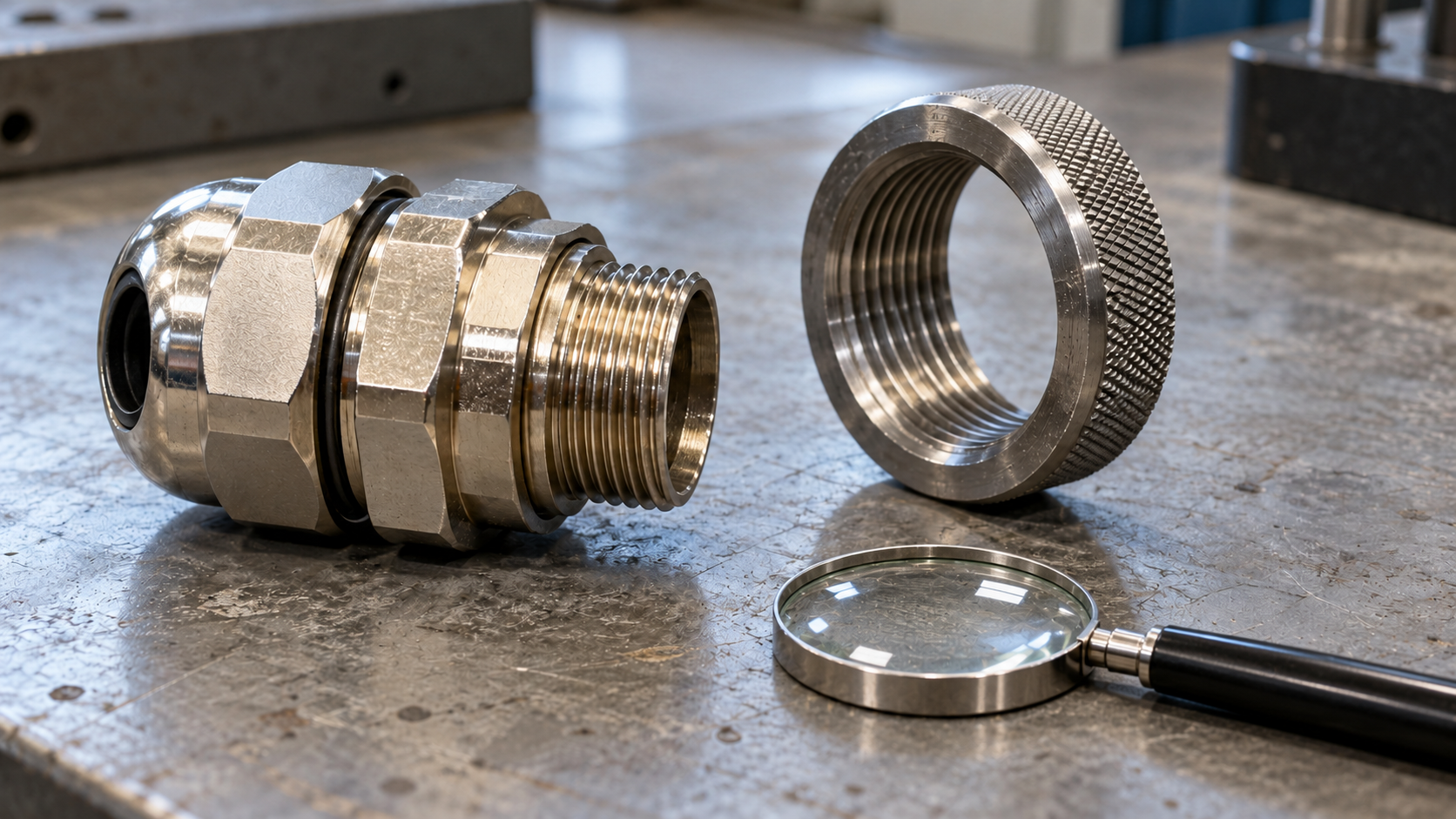
<figcaption>外露的引入螺紋與螺紋環件旁放著放大鏡，可供檢查表面。</figcaption>
</figure>
<table>
<thead>
<tr>
<th>方法</th>
<th>可回答的問題</th>
<th>仍有的限制</th>
</tr>
</thead>
<tbody>
<tr>
<td>卡尺</td>
<td>可接近的牙頂直徑是否與候選尺寸相符？</td>
<td>無法確認完整的功能性螺紋牙型</td>
</tr>
<tr>
<td>螺距規</td>
<td>間距是否近似指定螺距？</td>
<td>無法確認公差等級或導程精度</td>
</tr>
<tr>
<td>螺紋塞規</td>
<td>內螺紋是否符合指定的量規檢驗準則？</td>
<td>須使用正確的標準、尺寸、等級及程序</td>
</tr>
<tr>
<td>螺紋環規</td>
<td>外螺紋是否符合其量規檢驗準則？</td>
<td>須依據相應的外螺紋驗收基準</td>
</tr>
<tr>
<td>牙型輪廓或座標量測</td>
<td>各項已定義幾何尺寸的結果為何？</td>
<td>須具備合適的探測、對準及不確定度評估</td>
</tr>
</tbody>
</table>
<p><a href="https://knowledge.bsigroup.com/products/iso-general-purpose-metric-screw-threads-gauges-and-gauging">ISO 1502:1996</a> 涵蓋通用公制螺紋的量規與量規檢驗。<a href="https://knowledge.bsigroup.com/products/iso-general-purpose-metric-screw-threads-tolerances-principles-and-basic-data-3">ISO 965-1:2026</a> 涵蓋其公差系統。這些工作與計算基本牙型不同。NIST 的<a href="https://www.nist.gov/publications/pitch-diameter-measurement-threaded-gages-using-cmm">螺紋節徑量測論文</a>也指出使用 CMM 量測螺紋時的複雜性與不確定度。</p>
<p>可重現的結果須記錄圖面版次、量規識別及校正狀態、零件為成品或尚未完成的狀態、清潔狀態、相關溫度條件，以及所採用的驗收程序。對於採用不同規則的螺紋系列，不要套用通用的 NO-GO 規允許旋入圈數。</p>
<h2 id="conclusion-keep-geometry-attached-to-its-reference">結論：幾何尺寸須連同其參考基準</h2>
<p>定位大徑、螺紋節徑與小徑表面，為我們判讀電纜引入螺紋提供起點；軸向螺距與導程則應和牙型角、螺旋角及錐角分開。公制範例展示公稱直徑與螺距如何產生基本參考值，包括名稱必須保持正確的內螺紋小徑。</p>
<p>用這些數值判定零件前，請回到圖面的尺寸界限及量測方法。除了直徑，也要檢查實際牙底、完整螺紋長度、螺紋收尾及肩部。這樣的計算可協助溝通，而配合、密封及組裝驗收仍須依據指定證據判定。</p>
<h2 id="faq">常見問題</h2>
<h3 id="is-pitch-diameter-the-average-of-major-and-minor-diameters">螺紋節徑是大徑與小徑的平均值嗎？</h3>
<p>通常不是。它由螺紋的參考幾何形狀定義，不能任意將兩個量測直徑取平均。牙頂截短、牙底形狀及公差都會影響它。我在計算螺旋角時會使用指定的螺紋節徑或有依據的參考直徑，並記錄實際代入的值。</p>
<h3 id="does-the-metric-calculator-return-the-external-root-diameter">公制計算器會算出外螺紋牙底直徑嗎？</h3>
<p>不會。其小徑輸出是基本內螺紋小徑 D1。製成的外螺紋牙底另有自身的牙型與尺寸界限。即使舊參考圖沿用基本牙型標示，我仍會在對照計算值與圖面或量測結果時，把這些尺寸分開。</p>
<h3 id="why-can-equal-pitch-threads-have-different-lead-angles">相同螺距的螺紋為什麼會有不同的導程角？</h3>
<p>多線螺紋每旋轉一圈的導程，是螺距乘以起始線數。參考直徑也會改變該圈的周長。因此，導程與直徑都會影響角度。計算結果必須同時標示起始線數與參考表面。</p>
<h3 id="can-a-matching-pitch-leaf-replace-a-thread-plug-or-ring-gauge">螺距規能取代螺紋塞規或環規嗎？</h3>
<p>不能。螺距規可協助辨識間距。適用的塞規或環規則針對指定螺紋評估不同的驗收條件。需要判定符合性時，我會使用正確的量規與程序，並確認指定的零件狀態及最新校正紀錄。</p>
<h3 id="sources-and-technical-references">來源與技術參考資料</h3>
<ul>
<li>
<p><a href="https://rbb.union.edu/courses/mer419/content/data/Lectures/MER419%20L09%20Fastener%20Stiffness.pdf">Union College —《MER419 機械設計：接合用緊固件，公制牙型第 9 張投影片》</a>，查閱日期：2026-10-22。</p>
</li>
<li>
<p><a href="https://nvlpubs.nist.gov/nistpubs/Legacy/MP/nbsmiscellaneouspub61.pdf">美國國家標準局 —《國家螺紋委員會報告》，術語第 13–14 頁</a>，查閱日期：2026-10-22。</p>
</li>
<li>
<p><a href="https://knowledge.bsigroup.com/products/iso-general-purpose-metric-screw-threads-gauges-and-gauging">ISO 1502:1996 — ISO 通用公制螺紋：量規與量規檢驗</a>，查閱日期：2026-10-22。</p>
</li>
<li>
<p><a href="https://knowledge.bsigroup.com/products/iso-general-purpose-metric-screw-threads-tolerances-principles-and-basic-data-3">ISO 965-1:2026 — ISO 通用公制螺紋：公差原則</a>，查閱日期：2026-10-22。</p>
</li>
<li>
<p><a href="https://www.nist.gov/publications/pitch-diameter-measurement-threaded-gages-using-cmm">NIST —《使用 CMM 量測螺紋量規的螺紋節徑》</a>，查閱日期：2026-10-22。</p>
</li>
</ul>
