

Cable gland selection for VFD and motor termination needs a separate decision at each end. A variable frequency drive (VFD) and its motor may need different entry assemblies. The drive enclosure and motor terminal box may have different openings, finishes, available space and exposure, even with one screened cable between them. First define the required electrical path from the screen. Then match each end to the cable layers, sealing ranges, retention, entry hardware and current installation instructions.
Key takeaways
- Select the drive-end and motor-end entries separately; identical glands are a result, not an assumption.
- Match the outer jacket sealing range and the prepared screen-contact range as two distinct intervals.
- Treat the screen path, protective conductor, armour, sealing, and retention as separate functions.
- Include panel thickness, washers, adaptors, gaskets, and locknut engagement in the entry check.
- Use the exact drive, motor, cable, gland, and enclosure instructions for the final termination layout.
Start with the two termination endpoints
The drive and motor provide two different mounting locations. At the drive, the entry is in a converter enclosure or cabinet. At the motor, it is in a terminal box that may have a different material, wall, finish, opening and interior clearance. I would complete a selection row for each before deciding whether one gland assembly suits both.
IEC 61800-3:2022 specifies EMC requirements and specific test methods for power drive systems and machine tools. Its scope covers the drive system rather than assigning an EMC result to one entry component. IEC TS 60034-25:2022 addresses AC machines used in power drive systems and includes interface and installation guidance. Together, they point the designer back to the complete drive, cable, motor, and installation arrangement.
The broader VFD cable-gland engineering guide explains the full system boundary. This guide narrows the task to choosing and documenting the two physical terminations.
| Endpoint input | Drive enclosure | Motor terminal box |
|---|---|---|
| Entry geometry | Threaded wall or clearance hole, panel thickness, adaptor and locknut | Cast or fabricated box, thread or hole, wall thickness and internal space |
| Conductive interface | Cabinet reference surface, coating and bonding arrangement | Terminal-box material, finish and motor instructions |
| Cable preparation | Screen contact location, jacket strip length and internal routing | Screen contact location, conductor reach and bend into terminals |
| Environment | Cabinet location, heat, dust, liquids and cleaning | Motor heat, vibration, moisture, washdown and local exposure |
| Mechanical support | Cabinet cable tray or support point | Cable weight, bend, movement and terminal-box loading |
A termination endpoint is the complete cable-entry arrangement at one enclosure. It includes cable preparation, gland, accessories, wall, seating surface and internal routing. For example, a drive cabinet may have a threaded conductive wall and generous interior space. Its motor may have a painted clearance hole, washer, locknut and shallow terminal box.
The cable is unchanged, but the electrical contact to the enclosure, mounting thickness, entry seal and conductor reach differ. I would show them in separate drawing details. The drive-end gland may fit directly while the motor needs a longer thread or different accessories. The details should also show the surface receiving the screen path and the first cable support at each end.
Use current equipment and product drawings to set the actual screen preparation, component order, dimensions, and tightening values for each endpoint.
Define the intended screen path before comparing glands
Decide which conductive cable layer the gland must contact and where that contact connects to the enclosure. This is part of the electromagnetic compatibility (EMC) path. I would start with the drive and motor instructions, screen construction, and any filter or reactor instructions. Mark the intended screen contact at both ends on the electrical and mechanical drawings before comparing glands.
IEC TR 61000-5-2:1997 provides EMC-oriented guidance for earthing and cabling in electrical and electronic installations. For a machine, IEC 60204-1:2016+A1:2021 includes power drive systems, revised EMC requirements, and protective bonding requirements within its scope. The European Commission’s overview of the EMC Directive 2014/30/EU identifies the EU framework for electromagnetic compatibility of electrical and electronic equipment. These functions need a coordinated installation design, not a choice based only on gland body material.
Keep the following cable layers distinct:
- Outer jacket: the layer normally presented to the environmental seal and cable-retention system.
- EMC screen: braid, foil, tape, or combined construction presented to the specified contact component.
- Protective conductor: the conductor assigned to the protective-earthing arrangement by the electrical design.
- Armour, when present: the mechanical or electrical layer terminated by an armour-specific gland configuration.
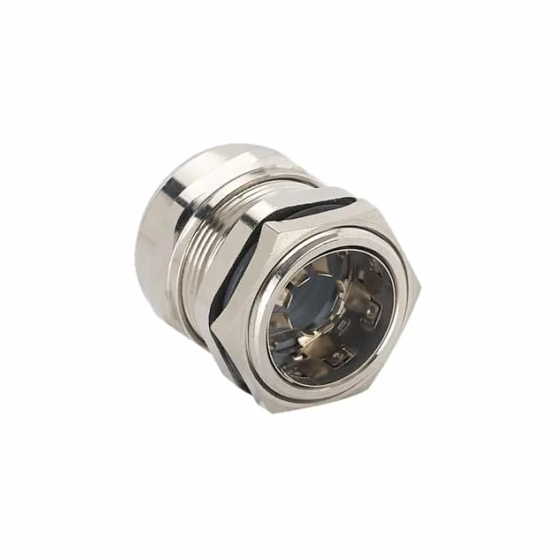
Match the spring’s declared contact range and preparation method to the selected cable, then follow the current model instructions for assembly.
A drain wire, braid, foil, protective conductor, and armour are not interchangeable labels. The shielded-cable gland specification method helps turn those cable-layer details into a usable schedule.
Match the cable to two dimensional interfaces
Check two diameters: the finished jacket at the seal and the prepared screen at its contact. I would compare each full tolerance interval with the declared range for the selected gland and contact design. Nominal conductor area and a catalog family name cannot replace either check.
The jacket sealing range is the interval of cable diameters accepted by the environmental seal. The prepared screen-contact range is the separate interval accepted by the contact component after cable preparation. Match both to the cable rather than use one diameter for two jobs.
Measure the finished cable at the intended seal location and retain its specified minimum, maximum, ovality and production tolerance. For screen contact, follow the gland’s preparation instructions and measure the exposed layer in that state. Folded-back or exposed braid, foil, tape and combined screens can present different shapes to the contact.
| Dimensional check | Input to record | Selection rule |
|---|---|---|
| Jacket sealing range | Finished cable OD minimum and maximum | The full interval fits within the exact gland’s declared cable range |
| Prepared screen range | Screen construction and prepared diameter interval | The specified contact component covers the prepared layer |
| Strip and reach dimensions | Jacket removal, screen preparation and conductor reach | Both endpoint layouts fit without forcing the cable bend or terminals |
| Entry bore and internal clearance | Gland bore, cable construction and terminal-box space | The prepared cable passes and can be assembled in the documented order |
The cable gland clamping-range guide explains interval matching for the outer cable surface. VFD termination adds the prepared-screen interval as a second, separate fit decision.
For example, two motor cables may have the same finished OD interval but different screens. One gland seal could fit both jackets, while its spring or cone fits only the prepared braid on one. The other cable may have foil, sparse braid or a different prepared diameter and need another documented contact method.
The reverse is also possible: the contact can fit both prepared screens while one jacket is outside the seal range. I would check both intervals against the cable variant, rather than let one nominal cable size or conductor-area label hide the mismatch.
Compare the enclosure interface at each end
At each enclosure, check how the gland seats, engages, seals and connects electrically. I would record the thread or clearance-hole size, usable wall thickness, coating, seating surface, adaptor, locknut, washer, gasket and internal clearance. Keep a separate set for the drive and motor.
A threaded metal drive cabinet and a painted motor terminal box with a clearance hole represent different assemblies. Even when their nominal entry sizes look similar, coating, wall thickness, adaptor use, and available male thread can change the gland choice. Confirm thread family, size, pitch where applicable, gender, and usable full-form thread length from the drawings.
For a through-hole installation, add every axial layer between the gland shoulder and the required locknut engagement. The stack can include the enclosure wall, flat washer, sealing washer or gasket, earth tag where the design uses one, adaptor shoulder, and thread runout allowance. A gland with an adequate cable range may still have insufficient usable thread for that stack.
Use the result as a geometry check, then compare it with the exact gland drawing and installation instructions. The responsible design authority sets the required engagement, compression, and acceptance criteria.

For example, usable male thread may be sufficient for a plain drive-cabinet wall but too short at the motor. A washer, adaptor shoulder, thicker casting and required locknut engagement each consume length. The cable seal and screen contact can fit while the mounting connection fails.
I would list each layer along the thread axis. That shows whether you need a longer-thread variant, different adaptor or another entry arrangement. Repeat the check when a washer, gasket, wall, adaptor or engagement requirement changes. The thread reserve depends on the assembled endpoint.
Check EMC, sealing, retention, and environment separately
I would review EMC contact, seals, retention and exposure as separate requirements. The screen contact provides the intended screened-cable path. It does not establish the cable or entry seal, retention, temperature range, vibration suitability, corrosion resistance or armour termination. Each needs a suitable product arrangement and installation condition.
IEC 62444:2010 specifies construction and performance requirements for complete cable glands as supplied by the responsible manufacturer or supplier. Use the exact variant’s declared cable range, accessories, instructions, and test documentation rather than transferring one family claim across sizes or configurations.
For enclosure protection, IEC 60529:1989+A1:1999+A2:2013 classifies degrees of protection provided by enclosures. Select the required IP code from the equipment and site specification, then verify that the gland, entry interface, unused openings, doors, joints, assembly, and maintenance together support that enclosure requirement. The IP selection method covers this branch in more detail.
Use these separate checks at each endpoint:
- EMC contact: cable screen type, preparation, contact range, enclosure interface, relevant frequency evidence, and installation method.
- Cable sealing: outer jacket material, complete OD interval, shape, surface condition, temperature, and exposure.
- Entry sealing: wall or thread geometry, seating face, gasket, washer, adaptor, orientation, and enclosure assembly.
- Retention: cable construction, support spacing, pull direction, static or moving duty, vibration, and product instruction.
- Materials: complete body, plating or finish, contact components, seals, accessories, and actual chemical or environmental exposure.
- Armour termination: armour type, dimensions, clamp geometry, continuity role, and the exact armoured-gland variant.
Build a termination-specific shortlist
Build the shortlist with one row for each proposed assembly at each end. I would mark every mandatory input as pass, reject or unresolved. Include the gland size, contact option, seal, thread, adaptor, washer, locknut and cable preparation. This makes it clear why a part fits the drive, the motor or both.
| Decision branch | Pass when | Reject when | Resolve before selection when |
|---|---|---|---|
| Screen path | Contact method and enclosure interface match the required termination | Cable screen or panel interface conflicts with the design | Screen topology or contact evidence is incomplete |
| Cable dimensions | Full jacket and prepared-screen intervals fit | Either interval falls outside the declared range | Cable tolerance or prepared diameter is missing |
| Entry geometry | Thread or hole, panel stack, seating face and clearance all fit | Thread family, usable length or assembly space conflicts | Coating, wall thickness or accessory stack is unknown |
| Other functions | Sealing, retention, environment and armour duties match | A required duty is outside the configuration’s scope | Site exposure or mechanical duty is not defined |
| Installation | Current instructions can be followed at that endpoint | Required preparation, torque or component order conflicts | Instruction revision or motor/drive detail is missing |
The two checks may select the same gland, different sizes within a family, different accessories or entirely different designs. Keep each result tied to its enclosure. If EMC problems remain after installation, I would use the EMC cable-gland troubleshooting path to locate the source, coupling path and affected equipment before changing parts.
Transfer the selected geometry into the termination drawings
Show the features the installer must reproduce at each end. I would identify the gland and accessories, enclosure entry, cable preparation, screen-contact position, seal position and component order. Add conductor reach, bend direction, support and any tightening instruction specific to that end.
Give the drive and motor details different identifiers, even when they use the same gland. A cable supplier, screen, terminal-box finish, wall thickness, adaptor or contact-option change then has a clear place for review. Do not assume a change leaves both terminations equivalent.
At installation, compare the received cable and gland markings with the drawing. Check that the correct parts are present, the cable has been prepared to the specified dimensions, the screen contact and seals sit on their assigned layers, and the enclosure seating interface is clean and assembled in the correct order. Route and support the cable so the first bend and cable weight do not load the entry beyond the documented arrangement.

Conclusion
My recommendation is to make two selection decisions using one cable definition. Establish the screen path first. Then check jacket sealing, prepared-screen contact, entry geometry, mounting thickness, retention, exposure and accessories independently at the drive and motor.
Place the two selection rows beside the current drive, motor, cable, gland and enclosure drawings. I would use one common gland only if every required field matches at both ends. Otherwise specify each termination separately and show its preparation and component order in the installation detail.
VFD and Motor Cable Gland FAQs
Must the drive and motor ends use the same cable gland?
No. The same screened cable can enter two enclosures with different threads, wall thicknesses, finishes, internal clearances, environments, and support conditions. Complete the drive-end and motor-end selection rows separately. Use the same gland only when its cable ranges, contact method, entry geometry, accessories, and installation instructions match both endpoints.
Is cable outside diameter enough to size a VFD cable gland?
No. The finished outside diameter controls the jacket seal, while the prepared screen can have a different contact diameter and construction. Record both intervals and their tolerances. Also check the entry bore, cable preparation length, conductor reach, and internal space required to assemble the termination without forcing the cable bend.
Does a metal cable gland automatically create the required EMC path?
No. The required path depends on the cable screen, contact component, gland body, enclosure interface, surface finish, accessories, and termination topology. Match that complete route to the current drive, motor, cable, and gland instructions. Keep protective-earthing and armour functions identified separately in the electrical and mechanical design.
How should an IP code be used in VFD gland selection?
Use the equipment and site specification to define the required enclosure protection, then select an entry configuration whose documented scope covers the cable, gland, gasket or washer, adaptor, wall, orientation, and assembly. Review the complete enclosure as well, including doors, joints, unused openings, maintenance, and every other cable entry.
What changes require the endpoint selection to be checked again?
Recheck the affected endpoint when the cable supplier or construction, outside diameter, prepared screen, gland size or contact, enclosure finish, wall thickness, entry thread, adaptor, gasket, support, environment, or installation instruction changes. A controlled comparison shows whether the original gland still matches or whether a new termination detail is needed.
Sources and technical references
- IEC 61800-3:2022, EMC requirements and test methods for power drive systems and machine tools, accessed 2026-09-11.
- IEC TS 60034-25:2022, AC electrical machines used in power drive systems, accessed 2026-09-11.
- IEC TR 61000-5-2:1997, EMC installation and mitigation guidance for earthing and cabling, accessed 2026-09-11.
- IEC 60204-1:2016+A1:2021, Electrical equipment of machines, accessed 2026-09-11.
- European Commission, Electromagnetic Compatibility (EMC) Directive 2014/30/EU, accessed 2026-09-11.
- IEC 62444:2010, Cable glands for electrical installations, accessed 2026-09-11.
- IEC 60529:1989+A1:1999+A2:2013, Degrees of protection provided by enclosures, accessed 2026-09-11.