

Cable gland thread conversion means checking whether two complete interfaces are compatible. NPT means National Pipe Taper; PG identifies the Panzergewinde steel-conduit thread family. Neither can be exchanged with a metric thread by nominal size alone. I identify both mating threads from the drawings or standards, then check fit and sealing. With an adapter, I check two separate joints. Similar diameters or a few hand turns cannot prove compatibility.
The entry must engage without damage, seat on the intended surface, preserve the specified seal and fit the surrounding wall or boss. I keep thread selection separate from product approval, ingress performance and hazardous-area suitability. A compatible thread alone cannot establish those other functions.
Key takeaways
- Never convert NPT, PG, and metric designations by nominal size alone.
- Identify the thread system, full designation, male/female form, geometry, dimensions, tolerance basis, and verification method for both sides.
- Treat an adapter as two independent threaded interfaces plus an installed stack and seal boundary.
- A successful trial start does not prove usable engagement, sealing, or approval.
- Stop when thread identity, usable engagement, sealing land, or installed geometry cannot be confirmed.
Cable gland thread conversion defined
Cable gland thread conversion determines whether the gland and enclosure can mate directly or need a fully specified adapter. Comparing labels does not physically change a thread. I verify each interface without damage and check whether the added adapter is covered by the required performance evidence.
ASME B1.20.1 covers several inch pipe-thread forms, including NPT. So “pipe thread” does not identify the full interface. DIN 40430 supplies dimensions for steel conduit thread commonly designated PG. IEC 60423 specifies conduit outside diameters and thread dimensions for its system.
IEC 62444 applies to complete cable glands supplied by the responsible manufacturer or supplier. Its public scope identifies metric entry threads and allows guidance for glands with other entry threads. I apply each standard to the interface it defines. These scopes do not establish interchangeability between NPT, PG and metric threads, or prove an adapter assembly’s performance.
Thread identity fields for comparison
I start two records: one for the gland-side interface and one for the equipment-side interface. Fill each from the controlled drawings or applicable standards. A generic chart, similar-looking sample or neighboring entry cannot resolve missing data.
Thread runout is the transition where the fully formed thread ends near a shoulder or relief. Usable engagement is the compatible, complete thread length or depth available after lead-ins, runout, damage, and obstructions are excluded. Both belong in the interface record because overall projection and drilled depth can overstate how much functional thread is available.
First define the thread. TPI means threads per inch, an inch-thread measure of spacing:
| Thread field | What to identify | Why it controls the comparison |
|---|---|---|
| Governing system | ASME, DIN, IEC, or the exact drawing standard | Similar labels can belong to different thread families. |
| Full designation | System name, nominal size, pitch or TPI where required, and drawing revision | A nominal size without system and pitch is incomplete. |
Next establish form and mating role.
| Thread field | What to identify | Why it controls the comparison |
|---|---|---|
| Thread role | External/male or internal/female | Two external threads need a coupling arrangement; two internal threads need a nipple-style arrangement. |
| Geometry | Tapered or parallel, profile, lead, and handedness if specified | Geometry controls how and where mating contact develops. |
Then define how that thread sits in the gland or equipment.
| Installed-interface field | What to identify | Why it controls the comparison |
|---|---|---|
| Dimensional limits | Relevant diameters, pitch, tolerance/class or gage basis | A crest reading alone does not establish functional fit. |
| Usable interface | Complete thread length/depth, lead-in, runout, counterbore, and seating face | Visible length can include sections that cannot engage. |
| Verification | Specified limit/plug/ring gage or controlled measurement method | The acceptance basis must match the governing document. |
For an M20 entry, the M20 specification breakdown explains the designation’s limits. I use that detail to identify the metric side, then follow this article’s cross-system checks. One metric size does not supply an equivalence table.
Why can’t nominal sizes be converted directly?
Nominal sizes identify threads within their own standards. Nearby crest diameters can still hide differences in profile, pitch, taper, tolerance or gauging. A nominal number may also differ from a caliper reading at one point. For example, lead-in clearance may let a gland start into a boss even though the pitches or complete thread flanks do not match. I stop rather than tighten through that uncertainty. Continued force can bind, cross-thread, strip coating or damage a part.
Regional preference cannot identify the thread either. One plant, skid or enclosure family may use several standards. I check the equipment drawing, controlled bill of materials, clear part marking and dimensions against the applicable standard.
How do you verify the gland and equipment interfaces?
Verify the two sides independently before comparing them. I identify whether the equipment has a tapped boss, threaded wall, removable plate or clearance hole with a locknut. Each arrangement has different mounting requirements, even if a nearby note uses the same nominal designation.
-
Establish provenance. Record the equipment drawing, gland drawing, revision, and part identity. Photograph markings only as supporting evidence.
-
Confirm male and female roles. Identify whether the gland and equipment provide external or internal threads and which component supplies retention.
-
Confirm thread identity. Check system, size, pitch or TPI, profile, taper/parallel geometry, tolerance or gage basis, and any coating allowance.
-
Check usable engagement. Exclude chamfers, incomplete runout, damaged turns, reliefs, and obstructed depth from the usable interface.
-
Locate the seal. Identify whether sealing is specified at the thread, a shoulder washer, an O-ring, a bonded seal, or another controlled surface.
-
Check the surrounding geometry. Confirm sealing-land width and flatness, recess, counterbore, wall thickness, projection, wrench access, and cable bend space.
After checking fit and seals, follow the actual installation instructions. The cable gland installation do’s and don’ts explains model-specific preparation, assembly, tightening, inspection and rework. I use the compatibility review to select an arrangement, then use those instructions to install it.
How should an adapter stack be evaluated?
An adapter adds interface A at the equipment and interface B at the gland. It also adds a stack of shoulders, seals, walls, locknuts or other retained parts. I check the identity and geometry of both joints separately.
For example, the female designation may match the gland but leave too little complete thread depth after excluding lead-in and runout. On the other side, the male designation may match the equipment while its shoulder lands on a radius, recess, coating buildup or interrupted surface. Correct labels do not guarantee correct engagement or sealing.
Check the stack in installation order:
- equipment wall, boss, or entry plate;
- equipment-side seal and seating surface;
- adapter body and usable equipment-side thread;
- adapter-side seal and seating surface;
- gland entry thread, shoulder, and any locknut or earth tag;
- internal and external projection plus wrench clearance.
The IEC 62444 selection guide explains how the standard relates to a complete product claim and its evidence. I recheck the installed arrangement when adding an adapter. The gland’s original report does not automatically qualify the adapter, enclosure interface or assembled ingress performance.
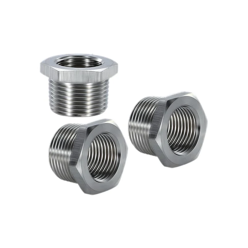
Three metal reducer bodies show external and internal threaded ends, shoulder faces, and wrench flats used when checking the two sides and installed position of an adapter.
Where does the cable-entry seal act?
Get the seal location from the component and assembly instructions. A connection may use thread sealing, a face washer, O-ring, bonded seal or another seating feature. Tightening a parallel thread does not by itself seal it; a tapered designation is also not a complete sealing specification.
With an adapter, I draw each ingress boundary: equipment to adapter, adapter to gland, and cable to gland. Check the seating width, flatness, coating, permitted seal and assembly order at each relevant surface. Stop for an unknown boundary rather than improvise a gasket or compound.
IEC 60529 classifies enclosure degrees of protection. An ingress protection (IP) code applies to the tested or assessed arrangement and conditions. Thread-name similarity cannot establish it. I use the IP-rating selection guide to define the required enclosure claim.
What material, electrical, and Ex boundaries remain?
Thread compatibility leaves other requirements open. Check material pairing, coating, exposure, bonding or screening, and hazardous-area suitability separately. A metal adapter’s appearance cannot prove corrosion compatibility, protective continuity, electromagnetic compatibility (EMC) or explosion-protection (Ex) suitability. For ordinary installations, I check the material specifications, coating interactions, environment, mechanical loads and manufacturer’s limits.
For electrical functions, identify the intended current or screen path and obtain evidence for the assembled arrangement. For hazardous areas, I check the certificate schedule, marking and protection concept first. Then check equipment group/category, gas or dust scope, cable, ambient range, accessories and special conditions. Do not transfer an Ex or IP claim from a gland to an undocumented adapter.
If material compatibility controls the decision, use the cable-gland materials guide. I record that decision in the thread review, while still completing the application’s corrosion, temperature and certification assessment.
How can you identify an unknown legacy entry without forcing a match?
Identify an unknown thread by measurements and elimination. First check whether the opening is threaded or intended for a locknut. Clean it without cutting the flanks, inspect damage and coating buildup, and establish whether it is parallel or tapered. I then compare possible NPT, PG and metric designations.
Calipers can screen crest diameter, and a pitch gauge can narrow the spacing or TPI. These remain provisional results. For taper, measure at more than one axial position and account for chamfer, runout, wear and coating. NIST’s pitch-diameter measurement paper identifies pitch diameter as the reference datum and warns that the measurement is often more complex than expected. Pitch diameter describes the reference diameter between the thread crests and roots. Compare candidates with the controlled limits and gauging method in the applicable ASME, DIN or IEC document. One matching diameter or gauge leaf is insufficient.

The surrounding entry can help identify the installation type. Check the flat sealing area, counterbore, boss depth, locknut space, wall thickness and signs of an old washer or O-ring. If form, taper, tolerance or usable depth remains unknown, I would obtain the equipment drawing or replace the entry plate with a known interface. Do not force a sample gland into it.
When is a conversion adapter not acceptable?
Reject an adapter if either threaded joint or its seal geometry remains unresolved. A correctly labeled NPT-to-metric or PG-to-metric part can still have too little complete engagement, a shoulder landing on a radius, or projection that obstructs bending or tool access. I check those conditions before accepting the label as a solution.
Reject the adapter approach when any of these conditions applies:
- either side lacks a complete thread designation, dimensional basis, or male/female definition;
- usable engagement is insufficient after chamfers, runout, coating, and damaged turns are excluded;
- the adapter shoulder, washer, or O-ring lacks the specified flat seating land;
- the body conflicts with a counterbore, thin wall, locknut, earth tag, enclosure recess, wrench path, or cable bend space;
- the added joint interrupts a required bonding or screen-termination path; or
- the required ingress or hazardous-area evidence does not cover the exact adapter, seals, enclosure interface, and installation conditions.
If the conflict cannot be resolved, I would select a gland with the required native thread or redesign the entry plate. Another reducer, improvised sealant or forced partial engagement cannot repair an incompatible interface.
Conclusion
I compare complete interfaces: system, pitch or TPI, taper or parallel form, limits, male/female roles and usable engagement. NPT, PG and metric labels are useful only after those details are known. For different direct threads, verify both sides of the selected adapter.
Then check seating, sealing, wall thickness, counterbores, projection, wrench access and cable bend space. I would have the equipment’s responsible engineer review the combination against component instructions and project conditions before installation. If the threads, sealing surfaces or installed geometry do not agree, choose a native-thread gland or redesign the entry.
FAQ: Cable gland thread conversion
Can an NPT gland fit a PG or metric entry with a similar diameter?
Similar diameter alone is insufficient. System, profile, pitch or TPI, taper or parallel form, dimensional limits, mating roles, usable engagement and sealing must agree. I would use a fully specified adapter only when both joints are qualified. Otherwise reject the combination or identify the missing drawing data.
Does a thread gauge prove an unknown cable-entry thread?
A pitch gauge narrows the candidates but does not establish the full designation. Check diameter limits, profile, taper, tolerance or gauging basis, usable depth or length, and the drawing or standard. I record the instrument, method, calibration status and result; one matching leaf is not final identification.
Does an adapter preserve the gland’s IP or Ex rating?
Not automatically. The adapter introduces another threaded joint, seal boundary, material interface, and installed stack. An IP or hazardous-area claim must cover the exact gland, adapter, enclosure interface, seals, cable, installation conditions, certificate schedule, and any special conditions required by the applicable evidence.
When should a conversion adapter be rejected?
Reject it when either thread is misidentified, usable engagement is insufficient, the seating land cannot support the specified seal, installed projection or access conflicts with the enclosure, or required configuration evidence excludes the added joint. If the controlling thread or seal data is unknown, stop and obtain the drawing rather than treating uncertainty as compatibility.
Sources and technical references
- ASME B1.20.1 — Pipe Threads, General Purpose, Inch, accessed 2026-09-24.
- DIN 40430 — Steel Conduit Thread; Dimensions, accessed 2026-09-24.
- NIST — Pitch Diameter Measurement of Threaded Gages Using a CMM, accessed 2026-09-24.
- IEC 60423:2007 — Conduit systems for cable management: outside diameters and threads, accessed 2026-09-24.
- IEC 62444:2010 — Cable glands for electrical installations, accessed 2026-09-24.
- IEC 60529 — Degrees of protection provided by enclosures, accessed 2026-09-24.