# Intumescent Cable Seals: Why Expansion Alone Is Not a Fire Rating
> Source: https://chinacableglands.com/blog/intumescent-cable-entry-seals/
> Language: en
> Publisher: Bepto Cable Glands
> Author: Brian Wu
> Published: 2026-10-22
> Updated: 2026-10-28
## Summary
Select intumescent cable seals by matching heat response, gaps, barrier construction, installation access and cable changes to the specified firestop system.
## Article
**Intumescent cable seals expand under heat to help close a cable penetration as its contents change.** I choose them as part of a complete firestop system: the barrier, opening, cables, sealing materials and supports must work together. The fire rating belongs to that tested or assessed arrangement. To select a suitable system, compare its permitted geometry and installation detail with the actual wall or floor penetration.
> **Key takeaways**
>
> - Expansion and protective char can close space and slow heat transfer when the material is held in the intended arrangement.
> - Match the barrier, cable types, opening, local gaps, seal depth and retention to the selected system.
> - Check material flammability, environmental sealing, penetration fire resistance and continued electrical operation as separate duties.
> - Plan the permitted method for adding or removing cables before choosing a system for a changing route.
## Identify the complete cable penetration
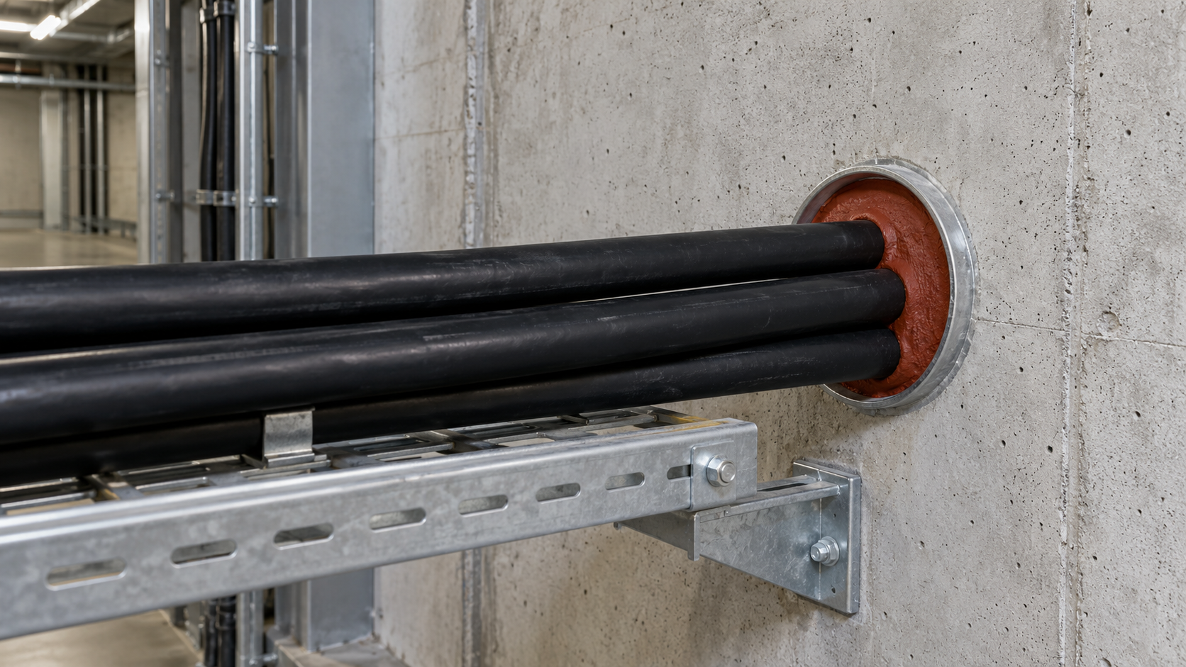
**A firestop system** is the arrangement used to protect a penetration through a fire-separating barrier. It includes the supporting wall or floor, opening, services and specified sealing components. Depending on the detail, a sleeve, frame, backing, packing or retaining device may also be required. I sketch the section from one face of the barrier to the other before selecting the material. That makes hidden depths and supports visible in the design review.
An equipment-wall gland and a building penetration perform different jobs along the cable route. The gland can grip and seal a cable at the enclosure. The building firestop maintains the required fire separation at the wall or floor. Where both are present, each needs its own suitable construction. The [fire-rated cable-gland guide](/blog/what-are-fire-rated-cable-glands-and-why-do-emergency-systems-need-them/) explains the gland's possible role in emergency electrical systems.
Start with the barrier type and thickness, opening dimensions, cable schedule and required fire performance. Then locate a system whose permitted arrangement fits those inputs. This sequence also exposes practical constraints: whether the back of the penetration is accessible, whether a sleeve is already cast in, and whether the cable support leaves enough space to install the seal correctly.
## How intumescent cable seals close a changing opening
**Intumescence** is an increase in material volume under heat. Many fire-protection formulations swell and form a protective char. The char can provide physical and thermal protection, as described in [NIST's research on intumescent fire protection](https://www.nist.gov/publications/intumescent-147instant-firewalls148-low-cost-fire-protection). That 2002 research addressed applications including aircraft fire barriers; the underlying mechanism helps explain why an expanding material can be useful around a penetration.
Cable coverings or other combustible parts may soften, change shape or be consumed during exposure. Material placed around them can expand into the emerging space. [UL Solutions' Firestop and Joint Application Guide](https://www.ul.com/sites/default/files/2024-10/Firestop-and-Joint-application-guide-final-draft-4-29-24pm-1.pdf) describes that void-filling action and the variation in expansion strength and amount between products. It also explains why securement matters for devices that contain intumescent material.
I compare the material's response with the opening it must close. The location and quantity of material, the available expansion direction and the means of holding it in place are practical selection inputs. A large free-expansion ratio gives little guidance about those interfaces. The useful question is whether the specified construction directs and retains the response where the cable leaves space.
Conceptual sections show sealing material before heating and expanded material filling space beside a reduced cable profile.
The green material starts around the cable and occupies more of the opening as the cable profile reduces. The surrounding barrier and the material's retained position matter as much as the visible swelling. Use the selected system's specified seal depth, packing and fixing detail to reproduce that arrangement. Activation temperature and expansion data belong to the particular formulation and test conditions; the installation dimensions come from the system detail.
## Separate the duties on the data sheet
**Material flammability** describes a specimen's behavior in a named flame test. **Penetration fire resistance** describes the performance of the barrier opening and sealing system under a fire test. An intumescent component may also seal against weather or leakage in ordinary service. I identify each required duty before comparing data sheets, because one installation can need all of them.
| Duty | What to look for | Where it applies |
| --- | --- | --- |
| Intumescent response | Specified material and heat-response conditions | Material behavior within the intended construction |
| Material flammability | Named test and classification for the relevant material specimen | Polymer or component material |
| Environmental sealing | Exposure, leakage test or enclosure rating for the assembled seal | Normal-service air, water or other environmental duty |
| Penetration fire resistance | System identity, barrier, services and fire-test result | Complete fire-separating penetration |
| Continued electrical operation | Cable-system performance under the required fire conditions | The critical electrical circuit and its supports/connections |
UL's [explanation of UL 94 limitations](https://code-authorities.ul.com/wp-content/uploads/2014/04/ul_UL94CertificationsAndLimitations.pdf) distinguishes small-scale plastic testing from building fire-resistance requirements. A V-0 classification describes the tested plastic specimen, while the penetration needs its own firestop result. Use the [UL 94 material-selection guide](/blog/what-ul-94-flame-retardancy-rating-do-you-need-for-non-metallic-cable-glands/) when the equipment specification also names a polymer flammability class.
For a wet location, check the seal's intended exposure before installation as well as its fire duty. A cured or compressed environmental seal works under different conditions from an expanded char. Where a gland is part of the entry, review its [wall-joint sealing arrangement](/blog/the-importance-of-entry-thread-seals-in-maintaining-enclosure-ip-ratings/) alongside the penetration system. This identifies which joint controls each possible leakage path.
## Read the fire-test result for the required duty
[ISO 10295-1:2026](https://www.evs.ee/en/iso-10295-1-2026), published in June 2026, addresses penetration sealing systems at fire-separating elements. Its scope evaluates the affected barrier and seal for integrity and insulation, with specified checks on penetrating services. Annex A includes optional water and air leakage tests.
**Integrity** concerns maintaining the fire-separating function under the test's criteria. **Insulation** concerns limiting heat transmission under its criteria. Read the report for the actual observations, limits and result. Then compare the named method and edition with the project's required route. A headline duration is useful only alongside the duty, test exposure and assembly to which it applies.
For example, closing the visible gap addresses only part of the fire-separation task. The seal and the penetrating service also form paths through which heat can reach the unexposed side. A cable may have a different thermal response from the surrounding char, while a metal sleeve adds another path through the barrier. This is why the ISO scope includes insulation performance of the penetrating services as well as the seal. I read the relevant result for each required duty before accepting a detail. When comparing two systems, match their barrier and service arrangements first, then compare the reported criteria. More visible expansion does not show how those heat paths behaved, and a flame-containment result alone does not describe the temperature response on the other side.
I check the system identifier and drawing revision first, then the barrier and service details. Next, I find the claimed fire performance and any separately required leakage results. This keeps the review tied to the installation and makes a missing duty visible. A requirement for both fire separation and air leakage, for example, calls for both results for the relevant arrangement.
Electrical circuit survival is another requirement. A penetration can maintain the barrier while the cable inside it loses electrical function. Where a circuit must keep operating, use the specified cable-system fire-survival method and installation, including its connections and supports. The [critical-circuit cable-gland guide](/blog/a-guide-to-fire-resistant-cable-glands-for-critical-circuits/) follows that functional selection process.
## Match the gap, depth and retention to the system
I compare the installation with the system section while the opening is still accessible. The visible face seal is only one part of that comparison; hidden backing, depth and retention can determine whether the intended construction is present.
The wall opening, cable group, surrounding seal and tray support form distinct parts of the penetration arrangement.
| Feature | Compare at the installation |
| --- | --- |
| Supporting barrier | Material, construction, thickness and wall or floor orientation |
| Opening | Shape, dimensions, sleeve or frame, and edge details |
| Services | Cable types, dimensions, count, grouping and permitted mixtures |
| Local spaces | Annular gap around each service, spacing between items and permitted fill |
| Seal construction | Exact materials, depth or quantity, backing and retention |
| Supports and access | Required support position, penetration angle and assembly sequence |
UL's [discussion of installed firestop variations](https://www.ul.com/thecodeauthority/knowledgecenter/beyond-installation-challenges-passive-fire-protection-compliance) identifies changes in aperture, cable size or count, annular space, angle and substrate as reasons an installation may differ from its tested design. Check those dimensions early. If the arrangement falls outside the system's permitted scope, select a suitable tested construction or obtain the project-required technical evaluation through the designer, system manufacturer and approving authority. An assessment should address the actual variation.
### Check installation access before choosing the form
On an existing cable route, I check access before settling on a sealing form. A backing layer placed inside the opening needs enough room for positioning and inspection. A surface-mounted device needs the specified fixing area and access for its fasteners. A sleeve or modular frame needs its permitted position in the barrier and the correct inserts or closure components. The UL application guide describes these different device forms and their specified assemblies. Match the proposed form to that installation detail, then confirm that the cable tray, enclosure or nearby services leave the working space it needs. If an obstruction prevents the required depth or fixing, resolve the layout before sealing. Choosing a smaller visible bead or omitting an inaccessible fixing would change the construction rather than solve the access problem.
### Check local clearance, not just the opening area
**Annular space** is the clearance between a penetrating service and the surrounding opening. For a round cable centered in a round opening, radial clearance is half the difference between their diameters. An offset cable has different gaps on opposite sides. The total open area remains the same, but the smallest and largest gaps change. That matters when the system detail specifies local gap limits or a particular cable position.
Consider an explicitly hypothetical 40 mm circular opening with one 20 mm round cable. Centered placement leaves 10 mm radial clearance. Moving the cable center 8 mm sideways leaves only 2 mm on the near side and 18 mm on the far side. The cable and hole still occupy the same areas. Suppose, solely for this comparison, that a selected detail permits 5–15 mm local gaps: the centered arrangement meets that geometric condition, while the offset one misses both limits. Both the dimensions and the gap limits here are assumptions for a geometry comparison. I measure the tight and wide sides before deciding on seal placement. For a real installation, use the actual permitted clearances and cable position. A change in positioning must also preserve the cable support, bend and other details of the selected system.
The assumed example can be written as $g_0=(D-d)/2$, with $g_{\min}=g_0-e$ and $g_{\max}=g_0+e$. Here, $D$ is the opening diameter, $d$ the cable diameter and $e$ the center offset, all in the same units. These geometric relations apply to the stated circular profiles with the cable wholly inside the opening. They describe clearance, not fire performance.
## Make future cable changes part of the selection
A route that changes often benefits from a system with a defined re-entry method. Before choosing it, check how cables can be added or removed, how spare positions are closed, and which components must be renewed after disturbance. An additional cable can alter local gaps, permitted fill and support. A removed cable leaves an opening that needs the specified closure.
I keep the system identifier and revision with the penetration location and installed cable schedule. Record component identities and the required inspections. Photographs taken before layers become hidden can help a later installer locate backing, fixings and support positions. Combine those images with the dimensions and inspection record, so future work can reconstruct the original arrangement rather than guessing from the finished face.
After an authorized change, restore the specified seal and supports, inspect the affected construction and update the cable schedule. Heat-affected, expanded, damaged or missing components require assessment and replacement as directed by the system instructions. Treat an expanded component as altered material; cooling does not restore the original installation detail.
## Conclusion
I select intumescent cable seals by following the heat response through the complete opening. The material must expand where space develops, remain supported and provide the required performance with the actual barrier and cables. Local clearances, depth and retention make that mechanism part of an installable system.
Choose the documented arrangement for the intended fire duty, check its normal-service sealing needs, and preserve the detail when cables change. Where the circuit must remain operational during fire, include that separate cable-system requirement in the design.
## FAQ
### Does every intumescent seal activate at the same temperature?
Activation behavior depends on the formulation and test conditions. Use the selected material's data for its heat response and the system instructions for installation. Match the permitted service environment as well as the fire duty.
### Can I add intumescent tape to an ordinary gland to make it fire rated?
Use a firestop or entry arrangement that specifically includes the gland and intumescent material in that configuration. Extra tape changes the fit and retention, so check the complete selected design before adding it. A rating belongs to its assessed system and conditions.
### Does a firestop rating show that the cable keeps working during fire?
A penetration rating concerns the barrier opening under its fire test. Continued electrical operation requires the specified cable or cable-system fire-survival performance. Include both duties when the design needs fire separation and an operating critical circuit.
### Can a spare cable be added through an existing intumescent seal?
Use the system's permitted re-entry method. Check the revised cable dimensions, count, gaps, fill and supports, then restore and inspect the seal. If the proposed arrangement exceeds the system scope, resolve the design or obtain the required technical evaluation before completing the change.
### Sources and technical references
- [NIST — Intumescent “Instant Firewalls” for Low-Cost Fire Protection](https://www.nist.gov/publications/intumescent-147instant-firewalls148-low-cost-fire-protection), accessed 2026-10-28.
- [UL Solutions — Firestop and Joint Application Guide](https://www.ul.com/sites/default/files/2024-10/Firestop-and-Joint-application-guide-final-draft-4-29-24pm-1.pdf), accessed 2026-10-28.
- [UL — Understanding UL 94 Certifications and Limitations](https://code-authorities.ul.com/wp-content/uploads/2014/04/ul_UL94CertificationsAndLimitations.pdf), accessed 2026-10-28.
- [EVS — ISO 10295-1:2026 — Fire testing of service installations: Penetration seals](https://www.evs.ee/en/iso-10295-1-2026), accessed 2026-10-28.
- [UL Solutions — Beyond Installation: Challenges in Passive Fire Protection Compliance](https://www.ul.com/thecodeauthority/knowledgecenter/beyond-installation-challenges-passive-fire-protection-compliance), accessed 2026-10-28.