# Gland Plate Layout: Will the Glands and Tools Fit?
> Source: https://chinacableglands.com/blog/gland-plate-circular-layout-open-area/
> Language: en
> Publisher: Bepto Cable Glands
> Author: Henry Xu
> Published: 2026-10-22
> Updated: 2026-10-28
## Summary
Calculate gland plate layout using chord spacing, hardware and tool envelopes, edge margins and open area, with worked six-hole and twelve-hole examples.
## Article
**For a circular gland plate layout, I use the straight chord between neighbouring hole centres to check clearance.** The arc along the pitch circle is longer and can overstate the available space. I compare the holes, installed hardware and tools in separate passes, then calculate the removed area against a clearly defined plate boundary.
The worked example starts with a six-hole plate and compares two twelve-hole alternatives. It shows why holes can fit while glands collide, and why a larger pitch circle can solve that collision while leaving too little room at the edge. Take the actual cut-out, hardware and mounting dimensions from the selected component and enclosure drawings.
> **Key takeaways**
>
> - Use chord spacing for the straight distance between adjacent entry centres.
> - Check holes, hardware and moving tools as separate envelopes.
> - Include the plate boundary, gasket zones, fixings and position tolerances.
> - Keep radius and diameter distinct when entering the calculator.
> - Use the area calculation to describe material removal, then verify the plate and enclosure design.
## Define the gland plate layout
I start with the plate boundary, its datum and the areas reserved for other functions. A perimeter gasket, fixing bolt, return flange or internal rail can make a nominally open region unusable. The [gland-plate design guide](/blog/a-guide-to-electrical-enclosure-cable-entry-plates-gland-plates/) covers these interfaces; the calculations here concentrate on their dimensions.
A **clearance envelope** is the space occupied by a component or needed for a tool to move. I keep three drawing layers separate:
| Layer | Dimensions to obtain | What I use it to check |
| --- | --- | --- |
| Cut-outs | Hole diameter, tolerance, location and any thread or anti-rotation feature | Hole separation and remaining plate material |
| Installed components | Body, cap, washer, locknut and internal projection | Interference and complete support of sealing surfaces |
| Assembly and service space | Tool head, approach, movement and removal path | Whether the installation remains accessible |
I take the hole diameter, tolerance and any thread or anti-rotation feature from the selected gland drawing. The [entry-thread specification guide](/blog/what-does-m20-cable-gland-actually-mean-a-spec-breakdown/) explains which dimensions sit behind a nominal thread label. A tapped thread and a clearance opening need different specifications, even when both carry the same nominal entry label.
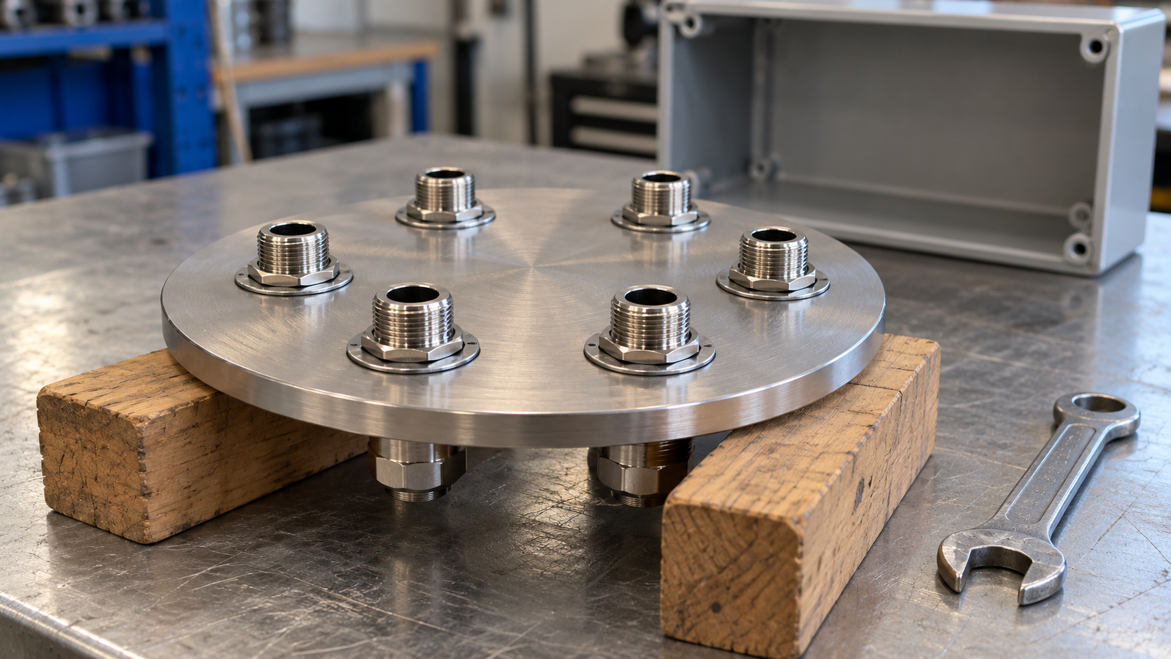
For the hypothetical example, use a circular plate 200 mm in diameter, six round holes 22 mm in diameter, and a 120 mm pitch-circle diameter. Each installed entry has a maximum circular plan envelope of 35 mm. These selected inputs let us compare layouts; use the dimensions from the actual hardware for a production drawing.
## Place equal entries on a pitch circle
A **pitch circle** is the circle passing through the entry centres. Let its radius be $R$, its centre be $(x_0,y_0)$ and the number of entries be the integer $n$, with $n\geq2$. Equal spacing gives:
$$
\Delta\alpha=\frac{360^\circ}{n}
$$
Choose a starting angle $\alpha_0$ from a defined drawing axis. For entry index $k=0,1,\ldots,n-1$:
$$
\alpha_k=\alpha_0+k\Delta\alpha
$$
$$
x_k=x_0+R\cos\alpha_k,\qquad y_k=y_0+R\sin\alpha_k
$$
Here the angles are in degrees, positive counterclockwise, with the drawing's positive y-axis pointing upward. This follows the [sine-and-cosine coordinate relationship](https://openstax.org/books/precalculus-2e/pages/5-2-unit-circle-sine-and-cosine-functions). I record the axis convention with the drawing so a CAD import uses the same orientation.
The six-hole example has a 60 mm radius and 60° angular pitch. With a starting angle of 0°, the centres relative to the plate centre are (60, 0), (30, 51.96), (−30, 51.96), (−60, 0), (−30, −51.96) and (30, −51.96), all in millimetres.
I check a transferred CAD layout from its coordinates as well as its pitch-circle label. For the first two example centres, the horizontal change is 30 mm and the vertical change is about 51.96 mm. Their straight-line distance is approximately 60 mm, matching the chord calculation. A different result directs me to the imported units, radius-versus-diameter entry and angle convention. I retain full precision in the calculation and round only the displayed coordinates; the drawing tolerance controls manufacture. Then I check the starting angle against the fixed bolts, flanges and cable approaches. Rotating the whole pattern changes those relationships while leaving adjacent chord spacing unchanged. On a rectangular plate, rotation can also change the closest edge margin. These checks catch different errors before the hole positions are released.
### [Circular Entry Pattern Calculator](https://chinacableglands.com/resource-center/tools/circular-entry-pattern-calculator/)
Category: Enclosure layout
Calculate angular pitch, chord pitch and circumference pitch for equally spaced entries on a circular pattern.
Formula: ` θ = 360° / n `
Inputs:
- Pattern radius
- Number of entries
Article note: Enter the pitch-circle radius, not its diameter: use 60 mm and 6 entries for the example. Compare the returned chord with actual component and tool envelopes.
## Compare chord spacing with arc spacing
A **chord** is the straight line joining two points on a circle. The centre-to-centre chord $c$ joins adjacent hole centres. The arc pitch $s$ is the distance following the pitch circle between those same centres:
$$
c=2R\sin\left(\frac{\pi}{n}\right),\qquad s=\frac{2\pi R}{n}
$$
These expressions use radians. Bisecting the triangle formed by the two radii gives the chord expression. The [arc-length relationship](https://openstax.org/books/precalculus-2e/pages/5-1-angles) gives the distance around the circle; dividing a full turn equally produces the stated arc pitch. The [cosine double-angle identity](https://dlmf.nist.gov/4.21) gives the equivalent check $c^2=2R^2[1-\cos(2\pi/n)]$ from the two centre coordinates.
With $R=60\,\mathrm{mm}$ and $n=6$, we obtain a chord of 60.00 mm and an arc of approximately 62.83 mm. Substituting arc pitch for chord pitch would overstate the actual centre spacing by 2.83 mm.
The straight chord measures the centre spacing used for circular-envelope checks; the curved arc follows the pitch circle between the same two centres.
For equal circular envelopes of diameter $D_e$, their nominal edge gap is $g=c-D_e$. The six 22 mm holes therefore have a 38 mm hole-edge gap. The larger 35 mm installed envelopes leave only 25 mm between them.
Increasing the count makes the distinction more consequential. Twelve entries on that same pitch circle have a chord of approximately 31.06 mm. The 22 mm holes still have a positive gap of 9.06 mm, while the 35 mm envelopes overlap by 3.94 mm. I change that pattern before choosing a tightening sequence because the installed envelopes already overlap.
For unlike adjacent circular envelopes, subtract half the sum of their diameters from their centre distance. Hexagons and other shapes need their actual orientation or a conservative enclosing circle. Across-flats width alone does not enclose the corners of a hexagon.
## Check edge margins and access separately
For a centred circular pattern on a circular plate, the shortest nominal radial margin from a hole edge to the plate edge is:
$$
m_h=R_p-R-\frac{D_h}{2}
$$
$R_p$ is the plate radius and $D_h$ is the hole diameter. The example gives $m_h=100-60-11=29\,\mathrm{mm}$. Replacing the hole diameter with the 35 mm envelope gives 22.5 mm from that envelope to the plate edge.
I then overlay the perimeter gasket zone, fixings and actual washer contact area. This shows how much of that margin remains available to support the entry seal. A clear plate edge dimension can still hide a conflict with a gasket or mounting feature.
On a rectangular plate, calculate each centre's distance to each straight boundary, then subtract the relevant envelope radius. I also check the closest internal obstruction. These distances use the actual outline rather than the circular-plate expression.
Nominal gaps also need tolerances. For example, if each adjacent centre can move by up to 0.5 mm toward the other, the nominal 25 mm hardware gap can reduce to 24 mm before any further envelope uncertainty. A specified position tolerance must be interpreted using its drawing convention; a diametral tolerance-zone value is not automatically a radial displacement.
Tool space is a moving envelope. I check the tool head, approach and working movement on both sides of the plate. Allow access to counterhold the body as well as turn the nut. The [gland-tightening guide](/blog/whats-the-perfect-torque-value-for-cable-glands-and-how-tight-is-too-tight/) explains the turning and counterholding points; the layout needs room for both tools. The [junction-box cut-out guide](/blog/how-to-customize-junction-boxes-like-a-pro-the-complete-guide-to-cutouts-holes-and-terminal-installation/) connects the layout to the subsequent machining and assembly checks.
Locknuts and washers occupy space around each entry, while the plate margin and surrounding gaps provide access for assembly.
## Calculate open area on a declared basis
**Open-area percentage** is the removed area divided by a declared plate area, multiplied by 100. For non-overlapping circular openings fully contained inside the plate, I add their individual areas:
$$
A_o=\sum_{i=1}^{n}\frac{\pi D_i^2}{4},\qquad \phi=\frac{A_o}{A_p}\times100\%
$$
$A_o$ is the removed opening area and $A_p$ is the declared reference plate area. Use consistent square units. If every opening has the same diameter, the sum becomes $n\pi D_h^2/4$.
The six 22 mm holes remove approximately 2,280.80 mm². Their percentage changes with the denominator:
| Declared plate boundary | Gross area | Six-hole open area |
| --- | --- | --- |
| Circular plate, 200 mm diameter | 31,415.93 mm² | 7.26% |
| Square plate, 200 × 200 mm | 40,000 mm² | 5.70% |
The removed area is identical in both rows. I record the plate boundary beside the percentage so readers can see why the two values differ.
If two of the six holes increase from 22 to 28 mm, the circular-plate result becomes 8.76%. This is a sum of four smaller circles and two larger ones; averaging their diameters first gives the wrong area because diameter is squared.
State whether the total includes fixing holes, connector cut-outs and other removed features. For slots or irregular cut-outs, use their actual profile area. Overlapping shapes require the union of the removed regions, not a sum that counts the overlap twice. For an edge notch, count only the portion removed from within the plate boundary.
A percentage based on usable area can also be useful, provided that area is explicitly drawn and named. It is a different metric from gross-plate open area. A 7.26% gross result cannot be compared directly with a competitor layout reported against a smaller usable region.
## Compare layout changes before cutting the plate
The same 200 mm plate can give very different clearance results when the hole count and pitch circle change. Keep the 22 mm holes and 35 mm hardware envelopes fixed for this comparison.
| Hypothetical layout | Pitch radius | Chord spacing | Hardware edge gap | Hardware-to-plate edge margin | Gross open area |
| --- | ---: | ---: | ---: | ---: | ---: |
| Six entries | 60 mm | 60.00 mm | 25.00 mm | 22.50 mm | 7.26% |
| Twelve entries, same pitch circle | 60 mm | 31.06 mm | −3.94 mm | 22.50 mm | 14.52% |
| Twelve entries, larger pitch circle | 77.28 mm | 40.00 mm | 5.00 mm | 5.22 mm | 14.52% |
For the last row, assume a desired nominal hardware gap of 5 mm. The required chord is then 35 + 5 = 40 mm. Rearranging the chord equation gives $R=40/[2\sin(\pi/12)]\approx77.274\,\mathrm{mm}$, rounded upward to 77.28 mm for the example. The 5 mm gap is an illustrative design target; the actual tool and assembly needs determine the required clearance.
I read the last two rows together. Moving twelve holes outward clears the circular hardware envelopes, while their total removed area stays the same. The outer hardware margin falls to 5.22 mm, so the next check is the gasket, edge support and fixing layout. A larger circle is useful only when those details still fit. If the washer or tool crosses a reserved region, I compare a larger plate, fewer entries or a different arrangement. Rotating the pattern may move an entry away from a fixed bolt, but it leaves neighbouring chord spacing unchanged. Changing the assembly order can help tool access, yet it cannot resolve the static overlap in the middle row. That is why I overlay the finished hardware before planning the tightening sequence.
## Verify the selected plate and enclosure design
After the layout fits, I review the remaining plate material and its load path. The same removed area can form a tight cluster, a line of holes or a widely distributed pattern. Check the narrow ligaments between openings, the plate material and thickness, the fixings and the loads from the installed cables. The area fraction is a useful drawing property; the structural review uses those dimensions and loads.
[IEC 62208:2023](https://webstore.iec.ch/en/publication/67906) addresses empty-enclosure characteristics and tests before switchgear and controlgear are incorporated. [IEC 60529](https://webstore.iec.ch/en/publication/2452) classifies enclosure protection. I use the applicable enclosure requirements and the manufacturer's modification instructions to plan verification of the finished assembly.
The worksheet now provides a located pattern with gaps, exclusions and removed area. Carry it into the plate and enclosure review with the exact entries, seals, material thickness and fixing details. Record the accepted revision so the machined plate and installation use the same dimensions.
## Conclusion
I begin a circular gland plate layout with the pitch circle, starting angle and actual component dimensions. Use chord spacing for adjacent circular-envelope checks, then distinguish hole clearance from hardware and moving tool space. Edge margins depend on the actual plate boundary, exclusions and tolerances.
The six- and twelve-hole comparison shows the trade-off: more entries reduce chord clearance, while moving them outward reduces the edge margin. I use the calculated dimensions to choose a workable pattern, check tool access and then verify the plate and enclosure with the selected hardware.
## FAQ about circular gland-plate layouts
### Should I use arc spacing or chord spacing between holes?
Use the straight chord for centre-to-centre clearance between adjacent round holes or circular component envelopes. Arc spacing follows the pitch circle and is longer. I retain the arc only when the drawing task actually needs distance along that circular path, rather than straight-line separation.
### Does a 120 mm pitch circle mean a 120 mm calculator radius?
No. If 120 mm is the pitch-circle diameter, its radius is 60 mm. The circular-entry calculator accepts radius. Entering the diameter in that field doubles the calculated chord and arc distances, although the angular pitch remains unchanged for the same entry count.
### Can a positive hole gap prove that two glands fit?
No. The body, washer, locknut, cap or tool can require more space than the opening. Compare the complete installed envelopes and their orientation, then include tolerances and tool movement. I also check the opposite plate face and cable approach because a clear outside view can hide an internal obstruction.
### What open-area percentage is acceptable for a gland plate?
There is no universal percentage in this calculation. The result measures removed area against a declared plate area; it does not establish stiffness, strength, sealing or enclosure conformity. Acceptance depends on the actual material, thickness, hole positions, loads, mounting and applicable enclosure requirements.
### Sources and technical references
- [NIST Digital Library of Mathematical Functions — Trigonometric identities](https://dlmf.nist.gov/4.21), accessed 2026-10-28.
- [OpenStax, Precalculus 2e — Angles, arc length and circle area](https://openstax.org/books/precalculus-2e/pages/5-1-angles), accessed 2026-10-28.
- [OpenStax, Precalculus 2e — Unit circle, sine and cosine](https://openstax.org/books/precalculus-2e/pages/5-2-unit-circle-sine-and-cosine-functions), accessed 2026-10-28.
- [IEC 62208:2023 — Empty enclosures for low-voltage switchgear and controlgear assemblies](https://webstore.iec.ch/en/publication/67906), accessed 2026-10-28.
- [IEC 60529 — Degrees of protection provided by enclosures](https://webstore.iec.ch/en/publication/2452), accessed 2026-10-28.