# Parallel Conductors: Check Current Density and Unequal Sharing
> Source: https://chinacableglands.com/blog/current-density-parallel-conductor-resistance/
> Language: en
> Publisher: Bepto Cable Glands
> Author: Victor Huang
> Published: 2026-10-22
> Updated: 2026-10-23
## Summary
Use metallic area for current-density comparisons and defined identical paths for parallel resistance, while keeping ampacity, sharing and terminal approval separate.
## Article
**Current density compares current with conductor area; a parallel-resistance calculation compares electrical paths. Neither calculation, on its own, establishes cable ampacity or permits conductors to be paralleled.** To use these models for a proposed arrangement, first identify the actual conductor, circuit condition and design basis.
The distinction matters at a cable entry. Metallic conductor area governs the electrical calculation, while finished cable diameter governs the gland or rear seal. You cannot obtain one from the other by treating the whole insulated cable as a solid conductor.
## Define the conductor area and current first
For an ideal uniform current distribution, average current density is:
$$
J=\frac{I}{A}
$$
Use current $I$ in amperes and metallic cross-sectional area $A$ in mm² to obtain A/mm². The area excludes insulation, jacket, air gaps between strands and other nonconducting parts. A cable with several circuit conductors also does not automatically offer the sum of all their areas to one current path.
Record whether the area is a specified nominal conductor size or a measured metallic area. [IEC 60228:2023](https://webstore.iec.ch/en/publication/71891) specifies nominal conductor areas and construction/resistance requirements within its scope. A nominal size is a designation used with those requirements; it should not be presented as a precision measurement of a particular specimen.
For a 24 A current and a stated 4 mm² area, the average density is 6 A/mm². If you enter 8 mm², the arithmetic gives 3 A/mm². That comparison says how current is normalized by area. It does not account for cooling, insulation temperature, grouping, installation method or the contact that terminates the wire.
The current condition needs to be explicit too. A DC calculation, an RMS current used for thermal comparison and a transient peak have different purposes. At frequencies or conductor sizes where current is nonuniform, this simple average cannot describe the local current distribution.
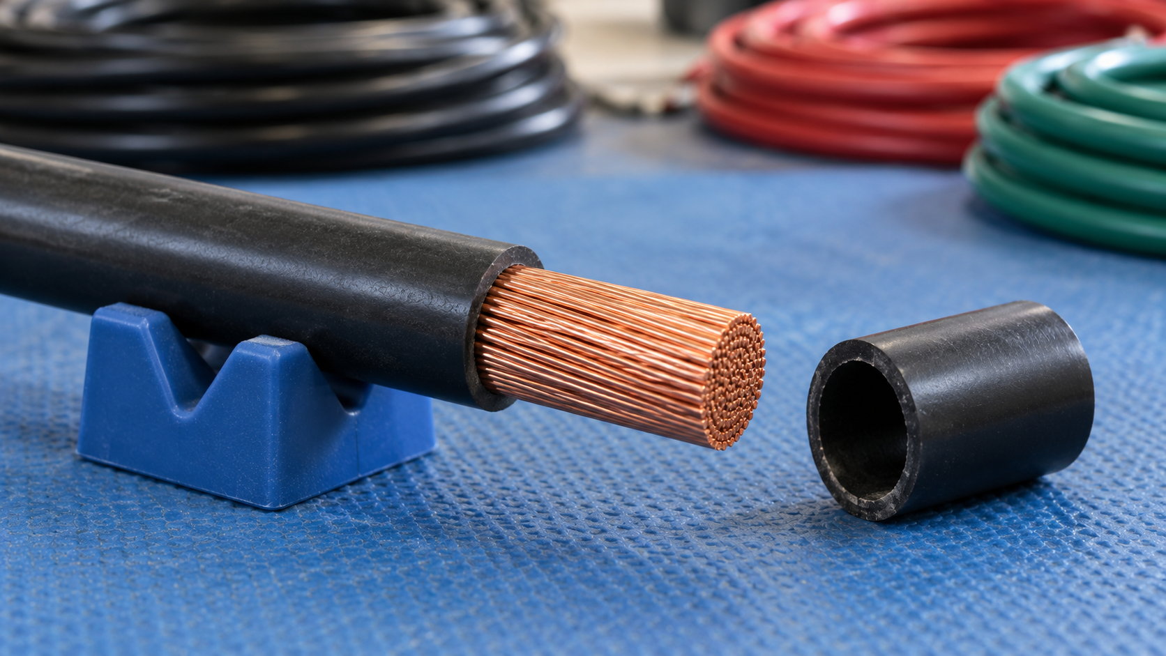
The exposed copper bundle and removed insulation separate the conductor metal from the overall insulated diameter.
## Compare with an entered density basis
A current-density calculator can show a margin against an entered project limit. If the illustrative 6 A/mm² result is compared with an independently supplied 7.5 A/mm² basis, the arithmetic margin is 1.5 A/mm² and utilization is 80%.
I would carry the source of 7.5 A/mm² beside the comparison. It is an assumed example input here, not a general recommendation. A positive margin against an undocumented number is not evidence that a cable will remain within its allowable temperature.
When reviewing two candidate conductors, use the same current condition and the same applicable comparison basis. If the basis changes with conductor construction or installation, record that change explicitly. Otherwise a neat comparison table can hide incompatible assumptions.
## Apply a specified retained fraction once
The site's preliminary current-capacity model multiplies area by a supplied design current density and a retained fraction:
$$
I_{\mathrm{base}}=A J_d,\qquad I_{\mathrm{prelim}}=A J_d\eta
$$
Here $J_d$ is the stated design density and $\eta$ is the fraction retained after the specified adjustment. For a hypothetical 6 mm² area, a supplied 5 A/mm² design basis and an 80% retained fraction, the outputs are 30 A before adjustment and 24 A after adjustment.
“Retain 80%” and “reduce by 80%” are different instructions. The first uses $\eta=0.8$; the second would retain 20%. Resolve that wording before entering a percentage.
Check whether the design density already includes the relevant thermal or grouping correction. Applying the same correction a second time would distort the comparison. Several correction factors should only be combined in the way required by the governing method, rather than multiplying convenient percentages gathered from unrelated documents.
This model is useful when an authoritative project basis supplies its inputs. It cannot create that basis from area alone. The [wire-gauge selection guide](/blog/a-guide-to-selecting-the-correct-wire-gauge-for-sealed-connectors/) explains the separate circuit, contact and sealing decisions.
## Calculate ideal resistance for identical parallel paths
For $n$ identical resistive paths of resistance $R$ connected between the same two nodes:
$$
R_{\mathrm{eq}}=\frac{R}{n},\qquad I_{\mathrm{each}}=\frac{I_{\mathrm{total}}}{n}
$$
The path count must be a positive integer. Equal current sharing follows from equal resistance and equal voltage across the branches. [RMIT University’s parallel-circuit guide](https://learninglab.rmit.edu.au/physics/electricity/parallel-circuits/) explains this parallel-circuit relationship. We can apply that relationship to an explicitly ideal conductor-path model.
For our example, each path is 0.060 Ω and three identical paths carry 30 A total. Their equivalent resistance is 0.020 Ω and each carries 10 A. The common drop is 0.60 V. Keep the resistance boundary consistent: a one-way conductor resistance is not automatically a complete outgoing-and-return circuit resistance.
### [Parallel Conductor Resistance Calculator](https://chinacableglands.com/resource-center/tools/parallel-conductor-resistance-calculator/)
Category: Electrical continuity
Calculate ideal equivalent resistance and current share for identical conductors connected in parallel.
Formula: ` Req = R1 / n `
Inputs:
- Single-conductor resistance
- Parallel conductors
- Total current
Article note: Enter the resistance of one complete defined path, an integer number of identical parallel paths and total current. Equal sharing is an assumption; verify actual permitted construction and branch impedances separately.
Identical here includes material, area, length, temperature and the termination contribution within the chosen boundary. The uniform-conductor relation $R=\rho L/A$ explains why length, area and material matter; the NBS [Copper Wire Tables](https://nvlpubs.nist.gov/nistpubs/Legacy/hb/nbshandbook100.pdf) presents that relationship and temperature-dependent resistance context. Actual cable resistance data may be more useful than calculating from an ideal solid cross-section.
## Show what unequal branches do to current sharing
Two paths need not share equally merely because they look similar. For resistive branches at the same voltage:
$$
\frac{1}{R_{\mathrm{eq}}}=\frac{1}{R_1}+\frac{1}{R_2},\qquad I_1=\frac{V}{R_1},\qquad I_2=\frac{V}{R_2}
$$
Consider two hypothetical paths of 0.020 Ω and 0.030 Ω carrying 30 A total. Their equivalent resistance is 0.012 Ω, so the common drop is 0.36 V. The lower-resistance path carries 18 A and the other carries 12 A. Assuming 15 A each would miss the higher-loaded branch.
Two unequal resistive paths divide the hypothetical total current according to their resistance, while sharing the same voltage drop.
This is a circuit model, not a terminal wiring proposal. I would check the actual conductors and connections for unequal lengths, areas, contact resistances and temperatures. For AC systems, impedance and arrangement may matter as well as DC resistance. The identical-path calculator does not model those differences.
A parallel cable path is also a different object from parallel photovoltaic source strings. The source currents, protection and connector rules of a PV array should not be replaced with the ideal conductor-sharing model above. For distributed cable and contact losses, the [voltage-drop guide](/blog/calculating-voltage-drop-in-solar-arrays-and-the-impact-of-connector-resistance/) keeps the resistance boundaries explicit.
## Complete the thermal and protection decisions separately
The preliminary arithmetic belongs alongside the adopted electrical design method and cannot replace it. [IEC 60287-1-1:2023](https://webstore.iec.ch/en/publication/68118) addresses cable current-rating calculations for its stated steady-state conditions and requires construction and environmental parameters. Its scope illustrates why a current-density number alone is insufficient.
The termination has its own current and temperature limits. [IEC 60512-5-2:2002](https://webstore.iec.ch/en/publication/2399) describes a current-temperature derating test for electromechanical components, particularly connectors. A conductor comparison does not establish a connector's tested current capability or whether its terminal accepts multiple conductors.
The proposed arrangement raises these distinct questions:
| Decision | Evidence needed beyond these formulas |
| --- | --- |
| Cable current rating | Adopted method, construction, cooling, ambient and grouping conditions |
| Parallel operation | Applicable wiring rules, permitted construction and actual branch sharing |
| Fault protection | Protection coordination and the relevant fault conditions |
| Termination | Exact contact or terminal, conductor range, number of conductors and preparation |
| Cable entry | Finished cable OD, gland range, support and enclosure geometry |
A lower equivalent resistance can reduce drop for a fixed total current, but it does not automatically double an allowable current or authorize a new assembly. Compare that benefit with the complete thermal, protection and interface requirements before choosing the arrangement.
## Conclusion
Current density is a useful normalized comparison when area, current condition and the comparison basis are explicit. A supplied design density and retained fraction can support an early estimate, while identical parallel paths provide a simple resistance and current-sharing model. Each result needs to stay attached to the assumptions that produced it.
The decisive checks remain the actual cable rating, permitted parallel arrangement, branch behavior and termination capability. You can use the arithmetic to expose an unequal path or a mistaken denominator without asking it to approve the entire circuit. At the enclosure, finish by checking the real cable diameter and entry geometry separately from metallic conductor area.
## FAQs about current density and parallel conductors
### Is current density the same as cable ampacity?
No. Current density divides current by conductor area. Ampacity or allowable current depends on the applicable design method and conditions such as cable construction, insulation temperature, cooling, grouping and installation. I use a density comparison only with an identified design basis; the result cannot independently establish the permitted circuit current.
### Does doubling conductor area always double the permitted current?
No. It changes the area used in a density calculation and generally changes resistance, but thermal behavior and installation conditions still govern the current rating. A larger conductor must also fit its exact contact, terminal and cable-entry arrangement. A simple area multiplier is not a complete sizing method.
### When can I divide one conductor resistance by the number of paths?
When the paths are identical within the defined resistance boundary and are connected between the same two nodes. Equal sharing also assumes equal branch conditions. I check length, material, area, temperature and terminations. The calculation does not itself authorize parallel operation or the connection of several conductors into one terminal.
### Does an 80% derating entry mean that current is reduced by 80%?
Not in a calculator asking for the retained percentage. An 80% retained fraction leaves four fifths of the unadjusted result, a 20% reduction. I read the input label and the source instruction together, then check whether that correction is already included in the design basis before applying it.
### Sources and technical references
- [IEC 60228:2023 — Conductors of insulated cables](https://webstore.iec.ch/en/publication/71891), accessed 2026-10-22.
- [RMIT University — Parallel circuits](https://learninglab.rmit.edu.au/physics/electricity/parallel-circuits/), accessed 2026-10-22.
- [NBS Handbook 100 — Copper Wire Tables](https://nvlpubs.nist.gov/nistpubs/Legacy/hb/nbshandbook100.pdf), accessed 2026-10-22.
- [IEC 60287-1-1:2023 — Electric cables, Calculation of the current rating](https://webstore.iec.ch/en/publication/68118), accessed 2026-10-22.
- [IEC 60512-5-2:2002 — Current-carrying capacity tests, Current-temperature derating](https://webstore.iec.ch/en/publication/2399), accessed 2026-10-22.