# Will the Cable Bend Fit? Calculate Enclosure Clearance
> Source: https://chinacableglands.com/blog/cable-bend-geometry-arc-chord-sagitta/
> Language: en
> Publisher: Bepto Cable Glands
> Author: Henry Xu
> Published: 2026-10-22
> Updated: 2026-10-28
## Summary
Calculate cable bend arc length, chord and sagitta from a defined centreline radius, then add cable thickness and entry allowances for enclosure clearance.
## Article
**A circular cable bend has three useful dimensions: arc length for the cable path, chord length between its endpoints, and sagitta for the rise above that chord.** I start with the permitted radius for the exact cable and duty, then calculate the curved path and occupied space from that radius. Keep the radius reference—inside surface or centreline—with the input throughout the calculation.
For enclosure routing, the cable centreline is only the starting point. The cable's thickness, straight sections and actual entry hardware all need space too. I check the jacket's outer envelope against the wall, guard and support locations, so a clear centreline also leaves room for the physical cable.
> **Key takeaways**
>
> - Use the cable's permitted radius for the actual installation or movement duty.
> - Convert an inside-surface radius to centreline radius before using the arc formulas.
> - Arc length estimates cable length; chord and sagitta locate the bend in the layout.
> - Add half the cable OD to the centreline envelope, then allow for variation and movement.
> - Count straight portions and termination allowances once, using clearly marked endpoints.
## Gather the cable bend inputs
I put the following inputs on the route drawing before calculating. This keeps a radius from one reference, an angle from another view and a clearance from a different datum from being mixed together.
| Input | Record on the drawing | What it controls |
| --- | --- | --- |
| Permitted bend radius | Value, radius reference, exact cable and applicable duty | The minimum curve used in the route |
| Cable outside diameter | Installed OD and specified size variation | The distance from centreline to jacket surface |
| Bend angle | Included angle and degrees or radians | Arc length, endpoint spacing and rise |
| Obstacle position | Surface location and orientation from the same datum | The nearest clearance to the cable envelope |
| Straight sections and allowances | Start/end points and whether end preparation is included | The total planned cable length |
## Put the radius on the right reference
**Centreline radius** is the distance from the centre of curvature to the cable's centreline. An inside-surface radius stops at the near surface; an outside-envelope radius reaches the far surface. For a round cable with outside diameter $D$, an undeformed circular cross-section gives:
$$
R_c=R_i+\frac{D}{2},\qquad R_o=R_c+\frac{D}{2}
$$
Here $R_i$, $R_c$ and $R_o$ are the inside, centreline and outside radii, all in the same length unit. Use this conversion for a round, undeformed cross-section. If the supported cable becomes oval or locally flattened, check its actual occupied profile in that state.
For example, a stated inside radius of 120 mm and a 12 mm cable OD correspond to a 126 mm centreline and a 132 mm outside envelope. If 120 mm instead means the centreline, the outside envelope is 126 mm. I would resolve that six-millimetre difference before drawing a close clearance.
The exact cable document must also distinguish installation, final training and repeated movement. Southwire's [Power Cable Installation Guide](https://www.southwire.com/medias/sys_master/installation-manuals/installation-manuals/h29/hb6/8887676141598/PowerCableInstallGuidepdf.pdf) distinguishes training radius from bends involving pulling tension. Use the current instructions for the selected cable construction and pulling or service condition when setting the permitted radius. Use the [bend-radius selection guide](/blog/how-does-cable-bending-radius-affect-your-cable-gland-selection/) when that cable-specific input is still missing.
## Calculate cable bend arc length
**Arc length** is the distance along the curved cable centreline between the bend endpoints. A full circle has circumference ${2}\pi R_c$, and the bend covers the fraction represented by its angle. Convert degrees $\alpha$ to radians $\theta$ using the [NIST degree-to-radian relationship](https://www.nist.gov/pml/special-publication-330/sp-330-section-4), then apply the [circular arc-length relation explained by OpenStax](https://openstax.org/books/precalculus-2e/pages/5-1-angles):
$$
\theta=\alpha\frac{\pi}{180},\qquad s=R_c\theta
$$
The result $s$ is centreline arc length, in the same unit as the radius. Keep the angle unit visible in the worksheet. A 90° bend is $\pi/2$ radians; enter the converted value when the formula expects radians.
For example, take two bends at an assumed 144 mm centreline radius. A 90° bend gives ${144}\times\pi/2=226.19$ mm. A 60° bend gives ${144}\times\pi/3=150.80$ mm. Those are different cable lengths even though the same radius is used. Use 144 mm here as a worked geometry input; set the radius in your own layout from the selected cable's limit.
If you change to metres, convert every straight length and radius consistently. A 0.144 m radius through 90° gives 0.22619 m, which is the same result. Round the final planning result to the precision supported by the drawing and routing method, then apply the specified cutting tolerance.
## Use chord and sagitta to locate the curved path
**Chord length** is the straight distance between the two bend endpoints. **Sagitta** is the maximum perpendicular rise from that chord to the chosen arc. The [circular-segment relationships in Wolfram MathWorld](https://mathworld.wolfram.com/CircularSegment.html) give the following expressions. Here I use bends greater than zero and no more than 180°, with the arc on the side of the chord shown in the diagram:
$$
c=2R_c\sin\left(\frac{\theta}{2}\right),\qquad h=R_c\left[1-\cos\left(\frac{\theta}{2}\right)\right]
$$
Use $c$ to position the endpoints and $h$ to locate the centreline rise above their chord. Use $s$ for the length of cable following the curve. To assess wall clearance, locate that wall on the same drawing datum before adding the cable's outer envelope.
The centreline arc, straight chord, midpoint rise and radius locate different parts of the same bend.
For the same 144 mm radius, the comparison is:
| Bend angle | Arc length | Chord length | Centreline sagitta |
| --- | --- | --- | --- |
| 60° | 150.80 mm | 144.00 mm | 19.29 mm |
| 90° | 226.19 mm | 203.65 mm | 42.18 mm |
| 180° | 452.39 mm | 288.00 mm | 144.00 mm |
For our 90° example and a 12 mm cable, the outer surface at the arc midpoint rises 48.18 mm above the centreline chord: 42.18 mm plus half the OD. Assume a flat obstruction sits parallel to the chord, on the arc side, 50 mm from it. In this hypothetical layout, I found only 1.82 mm of nominal clearance by subtracting the outside rise from the obstruction distance. Compare that gap with cable size variation, support position tolerance and expected movement before accepting the route. If those allowances consume the gap, move the obstruction, entry or support and draw the bend again. Keep the cable's permitted radius while changing the layout. For a wall at another angle, check the nearest point on the whole cable envelope; the midpoint rise may no longer be the closest approach.
### [Cable Bend Chord Clearance Calculator](https://chinacableglands.com/resource-center/tools/cable-bend-chord-clearance-calculator/)
Category: Cable dimensions
Calculate chord length, sagitta and arc length for a constant-radius cable bend when enclosure clearance is constrained.
Formula: ` h = R[1 − cos(θ/2)] `
Inputs:
- Bend centreline radius
- Included bend angle
Article note: Enter a verified centreline radius and included angle to compare arc length, chord and sagitta. Add cable thickness and the actual obstacle position separately.
The tool accepts a wider angle range, but a loop above 180° needs explicit major-arc interpretation and a complete envelope drawing. Restricting the simple chord-clearance comparison to minor arcs keeps the selected side of the chord unambiguous.
## Add straight sections and termination allowances once
### Locate the tangent points from the drawing corner
**Tangent setback** is the distance along either straight centreline from its virtual sharp corner to the point where the circular bend begins. I mark those points before measuring the straight cable portions. For two intersecting straight runs joined by a circular bend, with direction change $\theta$ greater than zero and less than 180°:
$$
t=R_c\tan\left(\frac{\theta}{2}\right)
$$
This follows from the [right-triangle tangent relationship](https://openstax.org/books/precalculus-2e/pages/5-4-right-triangle-trigonometry): the radius meets the straight run at a right angle, and bisecting the bend gives opposite side $t$ and adjacent side $R_c$. Use the change in travel direction for $\theta$, not its supplementary corner angle. A 180° return has parallel straight runs, so it needs a separate layout instead of a finite corner setback.
For the 144 mm radius and 90° bend, each setback is 144 mm. Suppose the two drawing dimensions to the virtual corner are 324 mm and 364 mm. Subtract the setback from each to obtain straight cable portions of 180 mm and 220 mm. These are the tangent-to-end lengths used in the total below.
If either available run is shorter than its setback, the chosen curve cannot fit between those endpoints. I move the entry or support and lay out the curve again, retaining the cable's permitted radius. Mark the bend's outer envelope after locating the tangent points so the clearance check uses the same geometry as the length calculation.
### Sum the defined route segments
Arc length is one part of the route. Mark where each straight section ends at a tangent point, then account for every curved segment and the separately specified termination or service allowance:
$$
L_{\mathrm{plan}}=\sum L_{\mathrm{straight}}+\sum s_{\mathrm{bend}}+L_{\mathrm{allowance}}
$$
Suppose the route has straight portions of 180 mm and 220 mm, joined by our 144 mm radius/90° bend. I first mark the tangent points where each straight joins the curve. The straight dimensions must stop at those points, rather than extend to an imagined sharp corner. With a separately specified 60 mm termination allowance, the total becomes 180 + 220 + 226.19 + 60 = 686.19 mm. If either straight dimension already includes the allowance, count it there and omit the extra 60 mm. Check the entry end too: a dimension from the enclosure seating face may include a gland, backshell or connector, while the cable starts elsewhere. A stripping length describes jacket removal and may lie within cable already counted. Mark those endpoints before turning this planning total into a cut length.
## Compare complete straight and right-angle entries
A right-angle entry changes the exit axis and where the cable's external bend begins. It may reduce outward projection while consuming more lateral space. A useful comparison overlays both complete assemblies on the same enclosure datum.
| Reserve in both options | Reason for keeping it in the layout |
| --- | --- |
| Installed gland, elbow and accessory envelope | Their projection determines the starting point of the external route |
| Required straight cable section | The first bend may need to begin beyond the seal or gripping zone; include any [spiral or bend-protection tail](/blog/a-guide-to-spiral-and-bend-protection-glands-for-dynamic-applications/) in the handoff to that bend |
| Cable outer envelope | The centreline alone does not locate the jacket surface |
| Tool and locknut access | An assembly that fits may still be inaccessible to install |
| Supports and door travel | Normal equipment movement can change the closest approach |
The [right-angle gland guide](/blog/a-guide-to-right-angle-cable-glands-for-tight-spaces/) explains the selection conditions. You can use the present geometry to compare its documented route with a straight-entry alternative, while retaining the cable maker's limit in both.
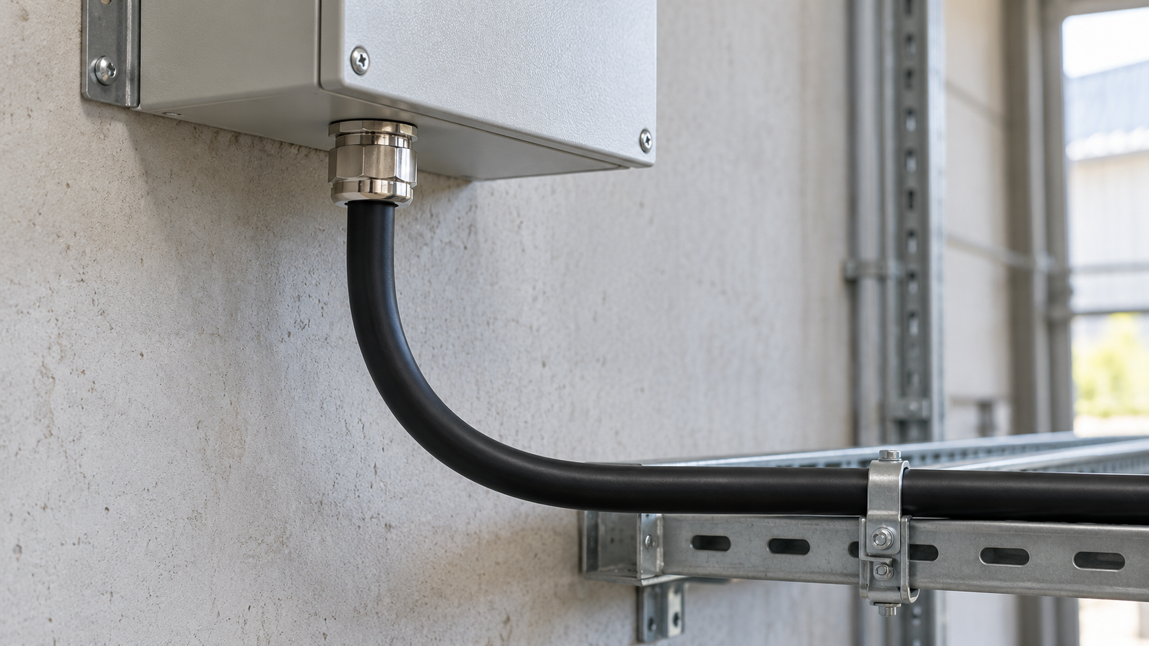
The cable leaves the gland in a straight section before curving toward a separate support.
## Recognise when the circular model stops being enough
A compound route can be estimated by summing straight segments and circular arcs, provided each tangent transition is defined. A free-hanging span, a twisted cable, a repeatedly moving loop or a cable being pulled around guides can change shape under load. Use a routing or mechanical model that represents that motion and the applicable cable instructions. For repeated travel, the [robotic and automated cable-routing guide](/blog/how-do-you-choose-the-right-cable-glands-for-robotic-and-automated-systems/) develops the support and movement decisions.
Even a static curve may shift when the cable springs back or supports are moved. Check the drawn envelope against the intended supported state and allow for the specified dimensional variation. Gland qualification remains separate: [IEC 62444:2010](https://webstore.iec.ch/en/publication/7034) covers the construction and performance of complete cable glands. Check the gland's sealing and retention for the selected cable and assembly alongside the route dimensions.
## Conclusion
Arc length estimates the curved cable path; chord and sagitta locate that path relative to its endpoints. With a defined centreline radius, we can calculate all three quantities and add the cable's thickness before assessing a close obstruction. Keeping the radius reference explicit prevents a small drawing convention from becoming a real clearance error.
For a usable enclosure layout, carry those results into the complete route. Add straight sections and allowances once, place the installed entry hardware on the same datum, and preserve room for supports, tools and normal movement. I use the resulting envelope to compare layouts, then verify the entry's sealing and grip with the cable and hardware actually installed.
## FAQs about cable bend geometry
### Is chord length the amount of cable needed for a bend?
No. Chord length is the straight distance between the bend endpoints. The cable follows the arc, which is longer for a nonzero bend angle. I use arc length in the route-length total and chord length to position the endpoints. Straight cable sections and separately specified termination allowances still need to be added.
### Can I use the minimum bend radius directly in these formulas?
Only after confirming its reference. The formulas use the cable centreline radius. If the cable document states an inside-surface radius, add half the outside diameter for a round, undeformed cable. Keep the stated installation or service condition with that value; the geometric conversion does not change the permitted cable duty.
### Does sagitta give the clearance to an enclosure wall?
Only when the wall's location and orientation are defined relative to the chord. Sagitta locates the centreline midpoint of the chosen arc. You must also include the cable thickness, dimensional variation and any movement. For a differently oriented obstacle, I check the whole cable envelope against the actual drawing.
### Does a right-angle gland eliminate the cable bend allowance?
No. It changes the entry geometry and exit direction. The complete internal and external cable path still needs to satisfy the exact cable and assembly requirements. I compare documented installed dimensions, straight-exit requirements, the cable envelope and tool access before deciding whether the right-angle arrangement saves useful space.
### Sources and technical references
- [Southwire — Power Cable Installation Guide](https://www.southwire.com/medias/sys_master/installation-manuals/installation-manuals/h29/hb6/8887676141598/PowerCableInstallGuidepdf.pdf), accessed 2026-10-28.
- [IEC 62444:2010 — Cable glands for electrical installations](https://webstore.iec.ch/en/publication/7034), accessed 2026-10-28.
- [NIST SP 330, Section 4 — Non-SI units accepted for use with the SI](https://www.nist.gov/pml/special-publication-330/sp-330-section-4), accessed 2026-10-28.
- [OpenStax Precalculus 2e, Section 5.1 — Angles](https://openstax.org/books/precalculus-2e/pages/5-1-angles), accessed 2026-10-28.
- [OpenStax Precalculus 2e, Section 5.4 — Right Triangle Trigonometry](https://openstax.org/books/precalculus-2e/pages/5-4-right-triangle-trigonometry), accessed 2026-10-28.
- [Wolfram MathWorld — Circular Segment](https://mathworld.wolfram.com/CircularSegment.html), accessed 2026-10-28.